PandaByte ADXL345 Accelerometer Module: I2C and SPI Communication Guide
by pandabyte in Circuits > Arduino
11 Views, 0 Favorites, 0 Comments
PandaByte ADXL345 Accelerometer Module: I2C and SPI Communication Guide
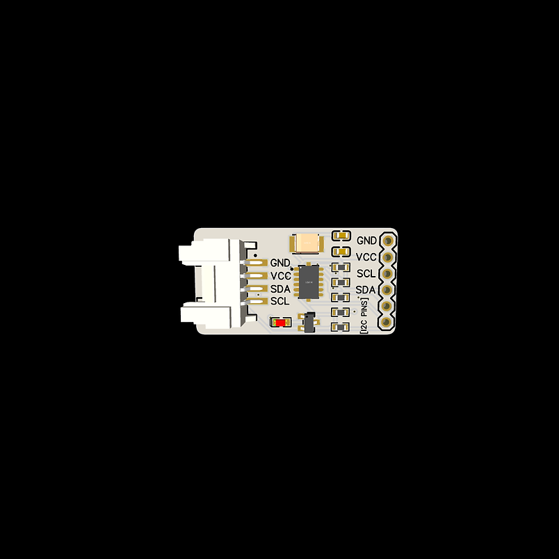
The PandaByte ADXL345 Accelerometer Module is a compact 3-axis digital accelerometer capable of measuring acceleration along the X, Y, and Z axes. It is widely used in applications such as motion detection, vibration monitoring, tilt sensing, robotics, wearable devices, and IoT systems.
One of the major advantages of the ADXL345 is that it supports both I2C and SPI communication, allowing users to choose the interface that best suits their application.
Like other PandaByte Grove modules, it supports both:
- Traditional male header connections
- 4-pin Grove connector for quick plug-and-play prototyping (For I2C only)
In this guide, you will learn:
- ADXL345 pin configuration
- I2C communication
- SPI communication
- Circuit connections
- Reading acceleration values
- Arduino programming examples
Supplies
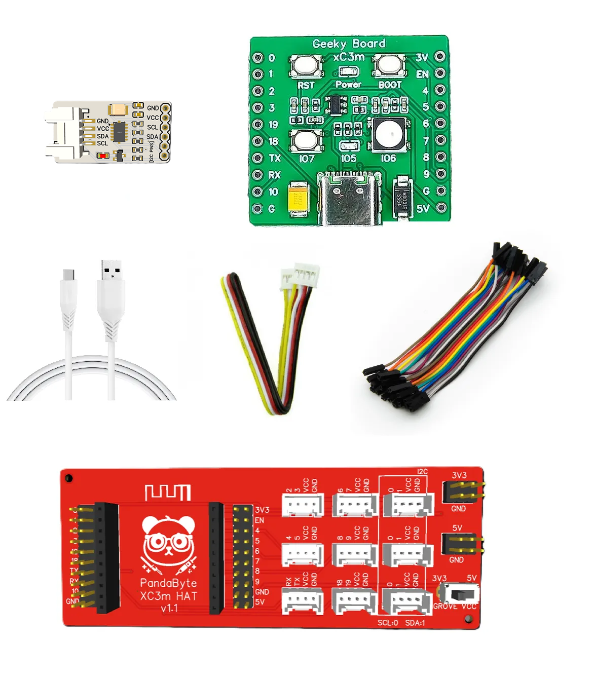
Hardware
- PandaByte ADXL345 Accelerometer Module
- PandaByte xC3m ESP32-C3 Development Board
- PandaByte Grove Expansion Board
- USB Cable
- Grove Cable (or Dupont jumper wires)
Software
- Arduino IDE
- SparkFun ADXL345 Library
Install Library
- Open Arduino IDE
- Sketch → Include Library → Manage Libraries
- Search for SparkFun ADXL345
- Install the library developed by SparkFun Electronics.
Circuit Connections
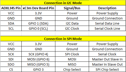
Perform the connection based on the table based on whether you are connecting in I2C or SPI mode.
Programming
Program 1: Reading Acceleration using I2C
Program 2: Reading Acceleration using SPI
Understanding the Output
The Serial Monitor displays three values:
where
- First value → X-axis acceleration
- Second value → Y-axis acceleration
- Third value → Z-axis acceleration
Rotate or tilt the sensor and observe how these values change.
When the module is placed flat on a table, the Z-axis will typically show the largest value due to Earth's gravitational acceleration.
Important Information
- The ADXL345 supports both I2C and SPI communication.
- I2C requires only SDA and SCL, making wiring simple and suitable for most projects.
- For PandaByte xC3m dev board, SDA and SCL pins are GPIO 1 and GPIO 0, respectively. If you are using a different dev board, make sure to connect the sensor to correct SCL and SDA pins.
- For PandaByte xC3m dev board, SPI pins are SCK (GPIO 4), MISO (GPIO 5), MOSI (GPIO 6). If you are using a different dev board, make sure to connect the sensor to correct SPI pins.
- SPI offers faster communication and is preferred in applications requiring higher sampling rates.
- The SparkFun ADXL345 library supports both communication modes using the same programming interface.
- The sensor measures acceleration along three independent axes (X, Y, and Z) and can detect motion, vibration, orientation, and free-fall events.