PandaByte GPS GNSS Module: Location Tracking
by pandabyte in Circuits > Arduino
24 Views, 0 Favorites, 0 Comments
PandaByte GPS GNSS Module: Location Tracking
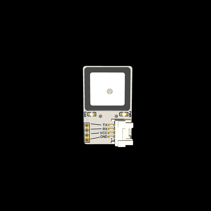
The PandaByte GPS Module is a GPS GNSS receiver capable of providing real-time latitude, longitude, altitude, UTC time, date, speed, and satellite information. It is suitable for applications such as vehicle tracking, asset monitoring, navigation, drone systems, wildlife monitoring, and IoT-based location-aware projects.
The module communicates with the microcontroller using a UART (Serial) interface, making it easy to interface with ESP32, Arduino, Raspberry Pi Pico, and other development boards.
Like other PandaByte Grove modules, it supports both:
- Traditional male header connections
- 4-pin Grove connector for plug-and-play prototyping
In this guide, you will learn:
- GPS module pin configuration
- UART communication
- Circuit connections
- Reading GPS coordinates
- Arduino programming using TinyGPSPlus
Supplies
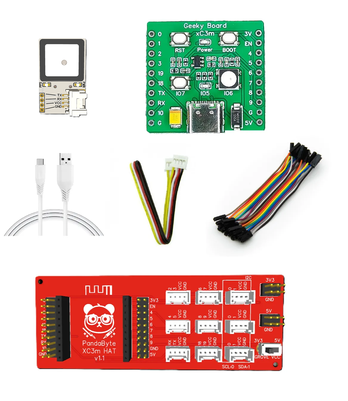
Hardware
- PandaByte GPS Module
- PandaByte xC3m ESP32-C3 Development Board
- PandaByte Grove Expansion Board
- USB Cable
- Grove Cable (or Dupont jumper wires)
Software
- Arduino IDE
- TinyGPSPlus Library by Mikal Hart
Install Library
Open Arduino IDE
Sketch → Include Library → Manage Libraries
Search for TinyGPSPlus
Install the library developed by Mikal Hart.
Circuit Connections
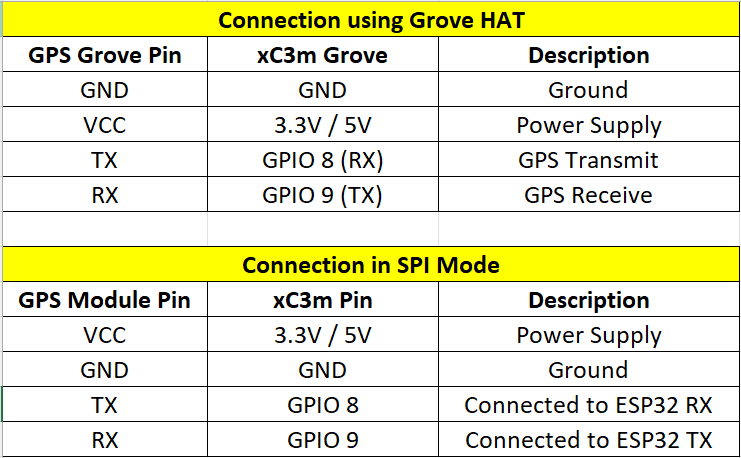
- Perform connection as per the table.
- Important: The module TX pin always connects to the microcontroller RX pin, and the module RX pin connects to the microcontroller TX pin.
Programming
Program to display time, Latitude, Longitude, and Altitude values on the serial monitor.
Output
The first GPS fix may take 2-5 minutes depending on satellite visibility. It is best to keep the GPS module outside in an open area to quickly lock to satellites.
After the GPS acquires satellites, the Serial Monitor displays values similar to:
If the GPS has not yet obtained a satellite lock, the Serial Monitor displays:
If no GPS module is detected:
Important Information
- The GPS module communicates using UART serial communication.
- The default baud rate is 9600 bps.
- For the xC3m ESP32-C3 board, GPIO 8 is configured as RX, while GPIO 9 is configured as TX.
- Always connect the GPS TX pin to the microcontroller RX pin, and the GPS RX pin to the microcontroller TX pin.
- The first position fix (cold start) may take longer than subsequent fixes.
- GPS modules work best outdoors with a clear view of the sky. Indoor reception may be weak or unavailable.