PandaByte LED + Switch Module: Digital Input and Output Guide
by pandabyte in Circuits > Arduino
9 Views, 0 Favorites, 0 Comments
PandaByte LED + Switch Module: Digital Input and Output Guide
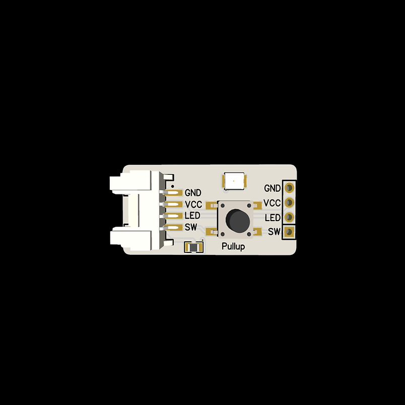
The PandaByte LED + Switch Module combines two of the most commonly used components for learning embedded systems—a single-color LED and a momentary push button—on a single compact board. It enables beginners to learn both digital output (LED control) and digital input (button reading) using a single module.
Like other PandaByte Grove modules, it supports both:
- Traditional male header connections
- 4-pin Grove connector for plug-and-play prototyping
In this guide, you will learn:
- Module pin configuration
- Circuit connections
- Reading push button input
- Controlling LED output
- Complete Arduino example
This module is suitable for Arduino-compatible boards, ESP32, Raspberry Pi Pico and other microcontrollers.
Supplies
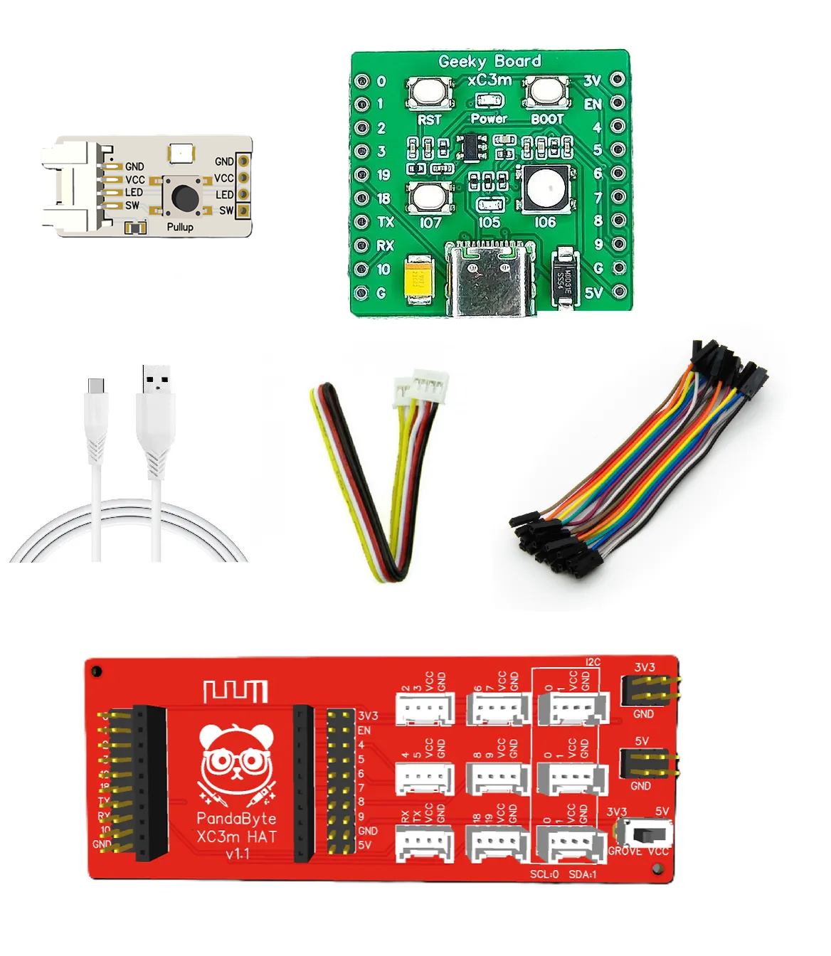
Hardware
- PandaByte LED + Switch Module
- PandaByte xC3m ESP32-C3 Development Board
- PandaByte Grove Expansion Board
- USB Cable
- Grove Cable (or Dupont wires)
Software
- Arduino IDE
Circuit Connections
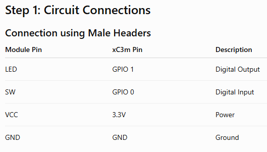
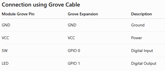
Perform the connection according to the table.
Programming
Program 1: Read the Switch
This example reads the push button using INPUT_PULLUP.
const int ledPin = 1;
const int switchPin = 0;
void setup() {
pinMode(ledPin, OUTPUT);
pinMode(switchPin, INPUT_PULLUP);
Serial.begin(115200);
}
void loop() {
if (digitalRead(switchPin) == LOW) {
Serial.println("Button Pressed");
}
else {
Serial.println("Button Released");
}
delay(100);
}
Program 2: Turn LED ON while Button is Pressed
const int ledPin = 1;
const int switchPin = 0;
void setup() {
pinMode(ledPin, OUTPUT);
pinMode(switchPin, INPUT_PULLUP);
}
void loop() {
if (digitalRead(switchPin) == LOW) {
digitalWrite(ledPin, HIGH);
}
else {
digitalWrite(ledPin, LOW);
}
}
Output
Program 1
- Serial Monitor displays:
- Button Pressed
- Button Released
Program 2
- Press the button.
- LED turns ON.
- Release the button.
- LED turns OFF.
Important Information
- The push button is configured using INPUT_PULLUP.
- With INPUT_PULLUP, the input normally reads HIGH, when button is not pressed.
- Pressing the button connects the pin to GND, so the input becomes LOW.
- The LED is connected to GPIO 1 and is controlled using standard digital output functions.