Pick-Me Lamps


You always wanted to have two cute portable Lamps that will give you a nice cozy light, wherever you bring them?
But here comes the twist. As soon as you turn one lamp on, the other lamp will constantly fight for your attention by trying to outshine its opponent. They will not let you have a single second without their annoying blinking and fighting. You turn one off and move it away? Oops... guess it does not care and will just turn itself back on again and drive right back to you to challenge its twin!
Below you will find the full instructions on how to build the lamps, all necessary 3D models and the complete code!
Have fun and enjoy our fun little project!
This project was developed by Yuma Shimizu, Priyansh Jain, Amrutha TV and Leo Adams as part of the Computational Design and Digital Fabrication Seminar in the Integrative Technologies & Architectural Design Research (ITECH) M.Sc. Program
Supplies

Here are all the supplies you need for each Lamp!
Lamp Body
The complete Body and mounting structure was printed on a 3D Printer.
You will find all 3D files you need for printing these listed parts below!
1x Lower Mounting Plate
1x Upper Mounting Plate
2x Custom Battery Case (3xAA/5xAA)
1x Outer Case Ring
1x Set of Monuting Pins to attach Outer Case Ring to Upper Mounting Plate
1x Lampshade
1x LED Mount Cylinder
Electronics
1x Arduino Nano
1x Breadboard (400 Pin)
1x L298N DC Motor Driver
2x N20 DC Motor (6V / 60rpm) get them with matching wheels! (ca 44x19mm) and brackets!
8x AA Batteries (8 x 1.5V)
1x LED RGB Strip (5V / 144 LEDs)
3x Light Dependent Resistors (LDR GL5528)
1x Push Button
3x 200Ω Resistors
1x 1kΩ Resistor
Lots of Jumper Cables (male/male and male/female - we just got a whole set of 120 cables
8x Battery Springs (recommended / not necessary)
Tools
6x M2.5 Bolts x Nuts (25mm)
4x M2.5 Bolts x Nuts (15mm)
4x M2.5 Bolts x Nuts (20mm or 25mm)
1x matching Allen Key
1x Tweezers (to hold the nuts)
1x Cutterknife
3D Printer and Filament
Tape!
You need eveything 2 times, so you can build both lamps!
Overview & Understand the Logic

Here, we briefly walk you through the logic.
Keep in mind that all the behaviours of the lamps are controlled only with light sensors; a light controlling a light.
Two Different States and Initial Setup_Stage 0-1
As you can see in the flowchart, there are two lamps set in different states: Lamp A and Lamp B. By default, both the lamps are set as Lamp A, so you need to press the button on one of the lamps to switch it to Lamp B, to have both states.
At Stage 1, Lamp A starts with lights=off and motor=off, while Lamp B lights a warm white colour.
Motion and Light Detection_Stage 2-3
As we mentioned in the beginning, motion is controlled by the values received from the light sensors(LDR) which are strategically placed around the lamp. Therefore, as soon as LampA finds another light source which is LampB, receiving LDR values, LampA moves towards LampB with a constant red light. LampA stops at a certain distance from LampB when its LDR values reach a threshold.
Light War and Light DetectionStage3-4
As LampA gets closer, LampB starts blinking because its LDR values also reach its threshold. When LampA stops, both LampA and B start blinking in red, starting a fight.
Loop_Stage5-1
The transition from stage ⑤ to ① is triggered by the user who gets annoyed by blinking lights and moves lamp A away from lamp B. Every time they stop and fight, their visit is recorded, so visit count indicates how many times they have met and been through the loop of ① to ⑤. Their behaviour changes according to visit count. As the count increases, the fight gets more and more aggressive, by increasing the blinking speed and changing the lighting colours.
Verification and State Switch_Stage5
at Stage ⑤, if visit count == 3 , state switch happens. Lamp A becomes Lamp B, and LampB becomes LampA, and the loop continues with switched roles.
After switching, visit count goes back to 0, to keep the loop again.
Assembly & Circuit

Here you can already familiarize yourself with the assembly logic and the circuit.
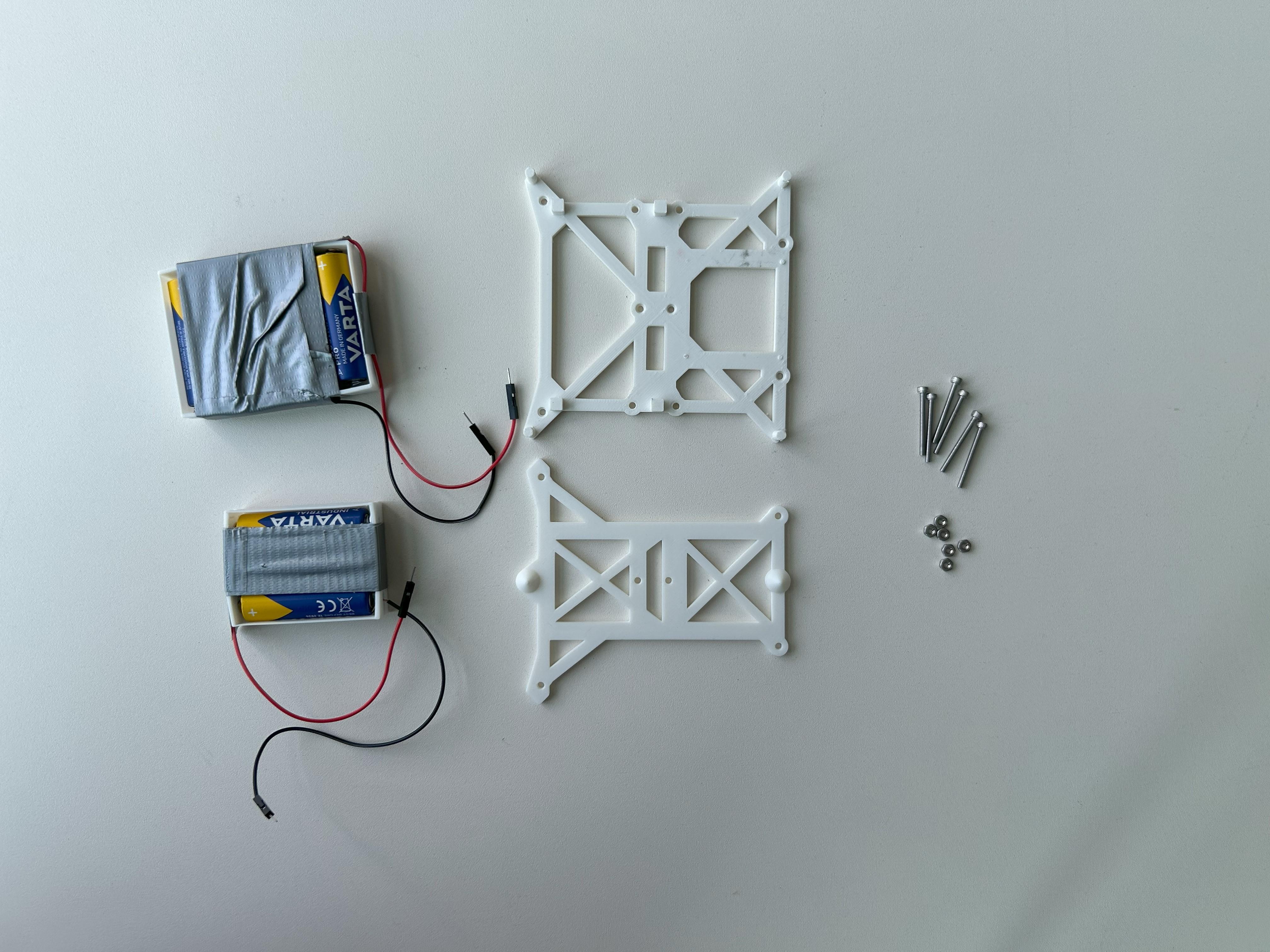
Battery Packs
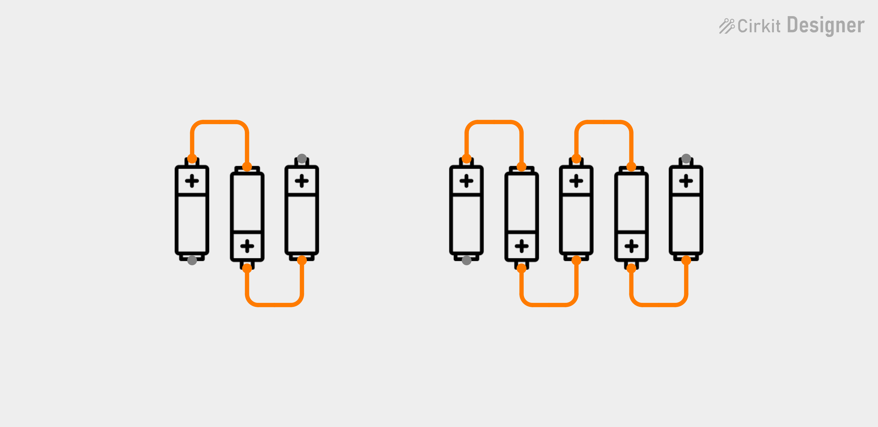


You’ll need:
- Two 3D-printed battery cases
- Four jumper cables (preferably 2 red, 2 black)
- A cutter knife
- 8 AA batteries
- Battery springs (optional)
Steps:
- Cut one end of each jumper cable so you have one male end and one open end.
- Insert the batteries into the 3D-printed case. Use springs between the batteries to maintain contact and pressure — especially for the first and last battery where the open jumper cables are attached. so you can loop the open ends around them (If you don’t have springs, solder the batteries together instead.)
- Wrap tape around the case to hold the batteries securely in place.
Installing Battery Packs

You’ll need:
- Upper & Lower Mounting Plates
- 6x M2.5 Bolts x Nuts (25mm)
- Assembled Battery Packs
Steps:
- Place the battery packs between the two mounting plates.
- Connect the plates via the bolts (Apply enough pressure to hold the battery packs in place.
Installing Motors


You’ll need:
- 2x N20 DC Motor (with brackets!)
- 4x M2.5 Bolts x Nuts (15mm)
- 4x Jumper Cables (open end)
Steps:
- Connect jumper cables to the positive and negative terminals of each motor (this will be difficult to do once mounted.)
- Fix the motors using the brackets and secure them to the upper mounting plate using the bolts.
- Route the motor cables through the upper mounting plate to to the front, where the L298N motor driver will be installed.
Setup & Install Breadboard


You’ll need:
- 1x Arduiono Nano
- 1x Breadboard
- 6x Jumper Cable (male/female)
- 8x small sized Jumper Cables (male/male)
- 4x medium sized Jumper Cables (male/male)
- 3x 200Ω Resistors
Steps:
- Mount the Arduino on the breadboard.
- Connect Arduino:
- Arduino 5V Pin (Line 12) → positive rail on Breadborad
- Arduino GND Pin (Line 14) → negative rail on Breadboard
- Connect the two negative rails to each other.
- Connect LDR:
- Arduino A0 Pin (Line 4) → Line 18
- Positive rail → Line 18
- Jumper Cable → Line 18
- Jumper Cable → Line 19
- Resistor → Line 19 & 21
- Negative rail → Line 21
- Repeat the connections for the other two LDRs (LDRs only shown in circuit diagram for reference, where to plug the cables. Dont install them yet.)
Setup & Install Motordriver


You’ll need:
- 1x L298N Motordriver
- 8x Jumper Cable
Steps:
- Connect:
- Motor Wires to L298N (OUT1-OUT4) as shown in Diagram
- L298N to Arduino (D2,D3,D4,D5,D9,D10) as shown in Diagram
- 7.5V Battery Positive → L298N 12V
- 7.5V Battery Negative → Negative Rail on Breadboard
- L298N GND → Negative Rail on Breadboard
- L298N 5V → Positive Rail on Breadboard (the one, the Arduino 5V is connected to)
- Mount the L298N on the upper mounting plate
Setup & Install Case


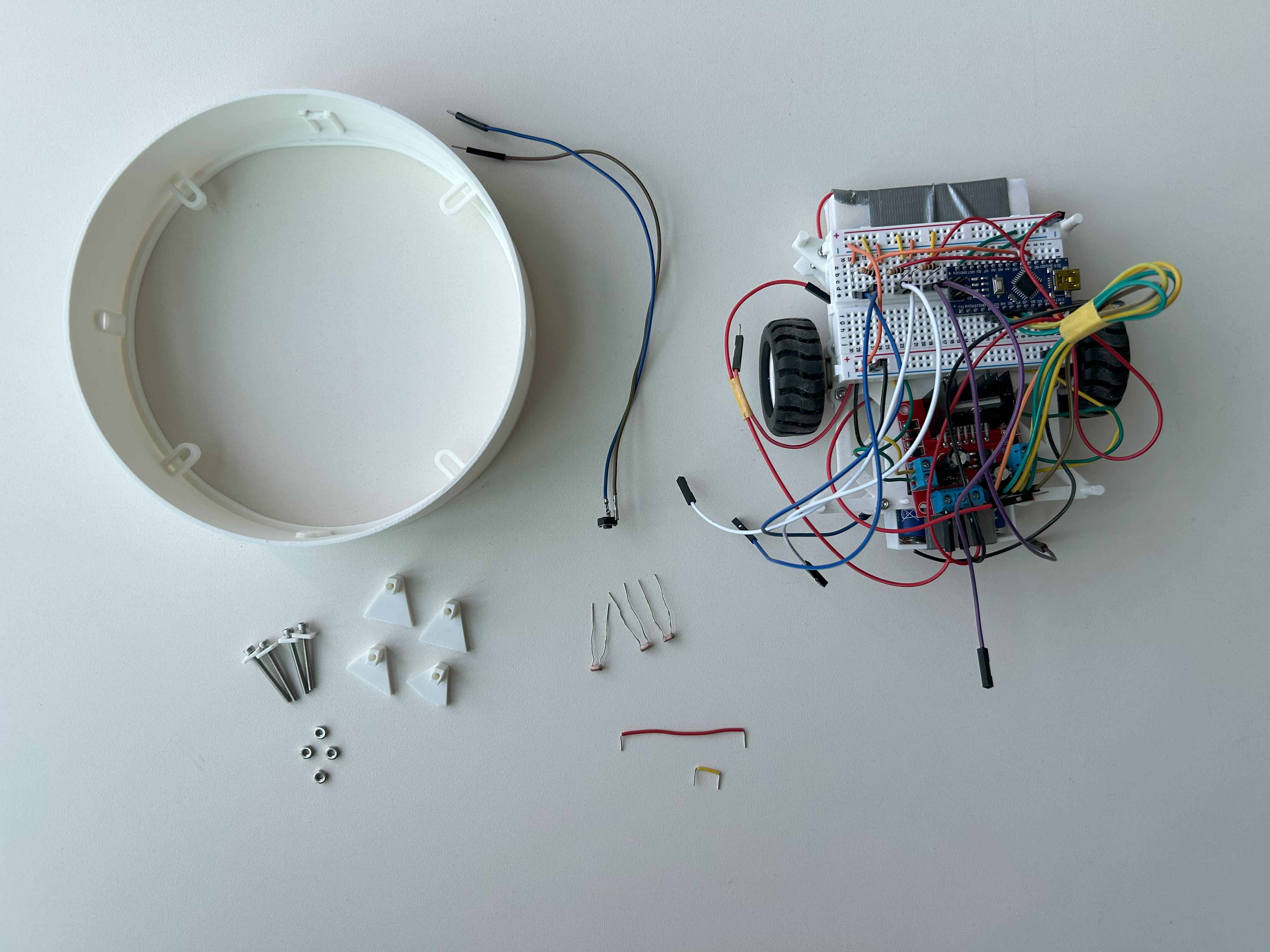

.jpeg)
You’ll need:
- 3x LDR
- 1x Push Button
- 1x Outer Case Ring
- 1x Set of Mounting Pins
- 4x M2.5 Bolts x Nuts (20mm or 25mm)
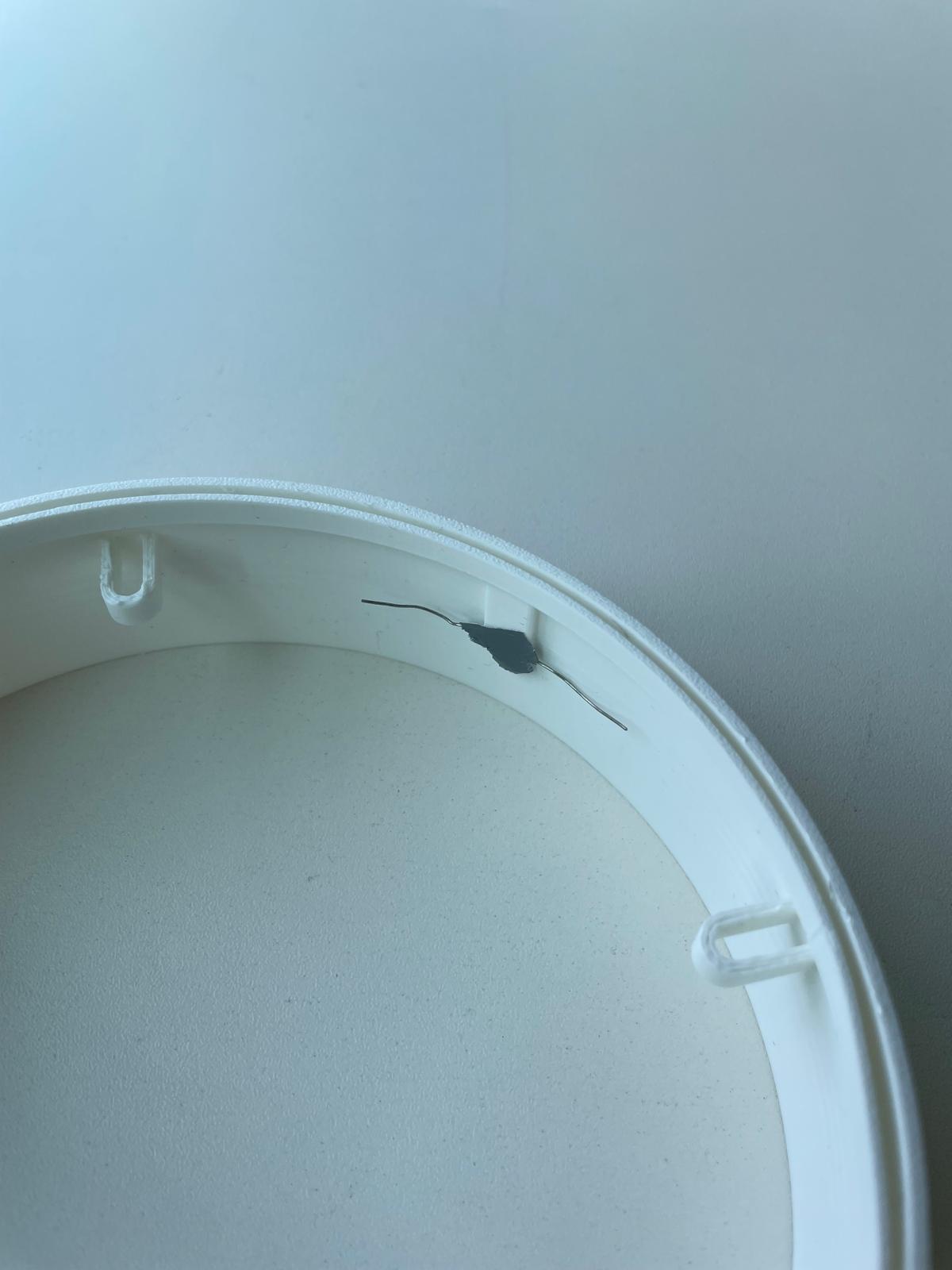
Steps:
- Insert each LDR into the ring’s predefined holes from the outside.
- Bend the legs of the LDRs button inside the ring and tape them in place.
- Insert the push button into the square cutout at the back of the ring.
- Position the case ring on the upper mounting plate with the button facing the back (behind the breadboard).
- Secure the outer case ring in place, using mounting pins and the bolts as shown in the picture.
- Connect the LDRs to the already installed Jumper Cables (Left on Line19/20, Middle on Line 22/23, Right on Line 26/27)
- Connect:
- Button → Line 26 & Line 27
- Arduino D7 (Line 6) → Line 26
- Line 26 → Positive Rail
- Line 27 → Negative Rail
Install LED


You’ll need:
- 1x LED Strip
- Mount Cylinder
- 2 Jumper Cables, matching the colors of your LED Cables (male/male)
- 1kΩ Resistor
Steps:
- Connect:
- LED GND → Breadboard negative rail
- LED DATA → Breadboard Line 21
- Resistor → Line 21 & 20
- Arduino D6 Pin → Line 20
- 4.5 Battery Negative → Breadboard negative rail
- 4.5 Battery Positive → LED Positive
- Stick the LED strip onto the mount cylinder and mount it on your robot.
Install Code
Install the provided Code onto your Arduino.
Downloads
Adjust Code
You can test the lamps individually with a flashlight. Initially the Lamp starts in State A. If you press the button for 2 seconds, State B is initiated.
Use a flashlight on the lamp to test if the behaviour is working as intended.
To get it running, you might need to adjust the light threshold values in the code, depending on how lit up your test environment is. Usually the darker the environment is, the better.
Have Fun
Now just get ready to send them down a spiral of an endless fight over your attention, trying to prove that they shine better than their opponent, while not giving you a single second of the nice lighting you actually want. Have fun!