Pico Thermostat Display
by JeremiahJ28 in Circuits > Raspberry Pi
330 Views, 0 Favorites, 0 Comments
Pico Thermostat Display


This project is a mini thermostat using a Raspberry Pi Pico 2W, a DHT11 sensor, and an SSD1306 OLED display. It reads the current temperature and humidity and displays them in real-time. It’s a great intro to environmental sensing and IoT projects.
Supplies


Materials List
- Raspberry Pi Pico 2W
- DHT11 Temperature & Humidity Sensor
- SSD1306 OLED Display (128x64, I2C)
- Jumper wires
- MicroUSB dongle
- Breadboard (for prototyping)
- Custom 3D-printed enclosure (STL included)
- Soldering tools (for final build)
- Hot Glue
Design the Circuit
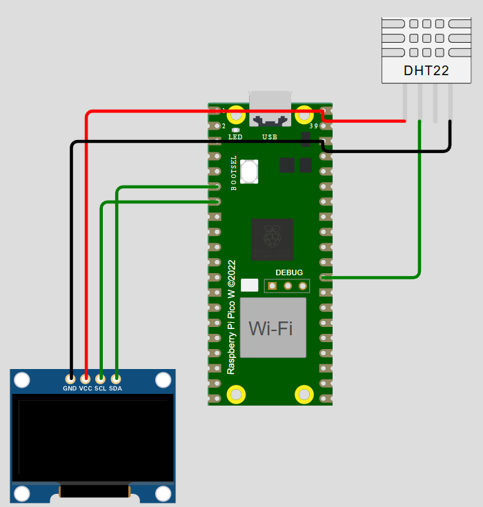

Step 1: Design the Circuit (WOKWI)
- Open the WOKWI project: Click Here
- Review the pin connections:
- DHT11 to GPIO 15
- SSD1306 (SCL to GPIO 1, SDA to GPIO 0)
- Power and ground appropriately wired
Flash the Code to Pico

Step 2: Flash the Code to Pico
- Install Thonny IDE
- Connect your Pico via USB
- Upload the MicroPython code (see code section below)
- Verify temperature and humidity readings appear on the display
I am unable to upload the font files with current extention (.pf) So I have renamed them to (.txt)
You will need to rename them back for it to work properly
Breadboard


Test everything on the breadboard first
Print the Enclosure

Step 3: Print the Enclosure
- Print the custom STL file provided
- Snap-fit the Pico, sensor, and display into the case
- I used the soldering Iron to melt the mounts for the OLED so they were a snug fit
- The Pico fits loosely...once I had wiring figured out I dropped a drop of Hot Glue behind teh pico when fitting it into teh case
- You can do either with the sensor, I made the mount long enough to melt, but I opted to put hot glue under mine.
Final Assembly


Step 4: Final Assembly
- Solder connections for a more permanent build
- Mount components securely in the case
- Power using USB and test the display
Reflection
Reflection
- Challenges: Sizing the STL properly to allow wires to pass through and accommodate the display.
- Lessons Learned: How to read from a sensor, display data, and prototype before printing.
- Improvements: Could add buttons to set a temperature threshold and trigger an alert.
- Future Plans:
- Building a few of these that will then use teh wireless function to communicate with a MASTER Pi who will then control the valves to allow heating to each room that requires it
- Including a waterproof one for the Hot Tub and Pool
- Monitoring a Chest Freezer temperature