Ping Pong Larson Scanner

So I saw the new tool to build circuits in http://123d.circuits.io, I decided to try it. And to my surprise, found that I could participate in a Contest here at instructables.
The circuit I made was inspired by a game of ping pong. For this, I used some LEDs, resistors and two servants to stay with a cool look. I hope you enjoy.
To see it working, I suggest using googlechorme browser:
http://123d.circuits.io/circuits/108085-ping-pong-larson-scanner/view
Portuguese:
Assim que vi a nova ferramenta para construir circuitos no http://123d.circuits.io, resolvi testá-la. E, para minha surpresa, descobri que tinha um Contest aqui no instructables e resolvi participar.
O circuito que fiz foi inspirado em uma partida de ping pong. Para isso, utilizei alguns leds, resistores e dois servos para ficar com um visual bem legal. Espero que gostem.
Para vê-lo funcionando, sugiro utilizar o navegador googlechorme:
http://123d.circuits.io/circuits/108085-ping-pong-larson-scanner/view
Components
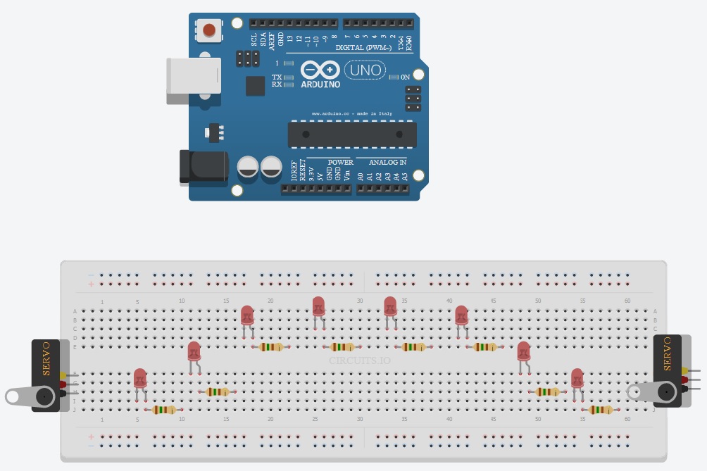
- 8 red LED's
- 8 resistors (150 ohms)
- 2 servomotors
- Wires, breadboard and an Arduino
Assemble the components as shown.:
Portuguese:
- 8 Led's vermelhos
- 8 resistores (150 ohms)
- 2 servomotores
- fios, protoboard e um Arduino
Montar os componentes conforme figura.
- 8 resistors (150 ohms)
- 2 servomotors
- Wires, breadboard and an Arduino
Assemble the components as shown.:
Portuguese:
- 8 Led's vermelhos
- 8 resistores (150 ohms)
- 2 servomotores
- fios, protoboard e um Arduino
Montar os componentes conforme figura.
Wiring

Connect the GND and Vin (or 5V) board with breadboard and then connect the outputs from the inputs of the Arduino, LED's and servomotors, following the guidance below.
Portuguese:
Ligar o GND e o Vin (ou o 5V) da placa com o protoboard e, em seguida ligar as saídas do Arduino nas entradas dos led's e dos Servos, seguindo a orientação abaixo.
Portuguese:
Ligar o GND e o Vin (ou o 5V) da placa com o protoboard e, em seguida ligar as saídas do Arduino nas entradas dos led's e dos Servos, seguindo a orientação abaixo.
Software


To insert the software, first click on the Arduino. After that, it shows the code editor below the breadboard. click it and the screen appears to enter the software.
Portuguese:
Para inserir o software, primeiro clique no Arduino. Em baixo do protoboard irá aparecer o editor de código. clique nele e aparecerá a tela para inserir o software.
Software:
#include <Servo.h>
Servo myservoR;
Servo myservoL;
int val;
int pinArray[] = {12, 11, 10, 9, 8, 7, 6, 5};
int count = 0;
int timer = 25;
void setup(){
myservoR.attach(3);
myservoL.attach(13);
for (count=0;count<8;count++) {
pinMode(pinArray[count], OUTPUT);
}
}
void loop() {
for (count=0;count<8;count++) {
digitalWrite(pinArray[count], HIGH);
delay(timer);
digitalWrite(pinArray[count + 1], HIGH);
val= (count*22.5);
myservoR.write(val);
myservoL.write(val);
delay(timer);
digitalWrite(pinArray[count], LOW);
delay(timer*2);
}
for (count=7;count>0;count--) {
digitalWrite(pinArray[count], HIGH);
digitalWrite(pinArray[count], HIGH);
delay(timer);
digitalWrite(pinArray[count - 1], HIGH);
val=(count*22.5);
myservoR.write(val);
myservoL.write(val);
delay(timer);
digitalWrite(pinArray[count], LOW);
delay(timer*2);
}
}