Planner


This project shows you how to create a simple planner using gen4-uLCD-50DCT-CLB. The keyboard widgets from ViSi environment is utilized in this project to allow the user to create plans on a future date.
When powering the module for the first time, the user is required to set the date and time. DIABLO16 uses its system clock to update the set time to calculate the current date and time. The project saves the plans in a FAT16 formatted uSD card and displays it on the set day for the user to view.
How It Works

Components


- gen4-uLCD-50DCT-CLB
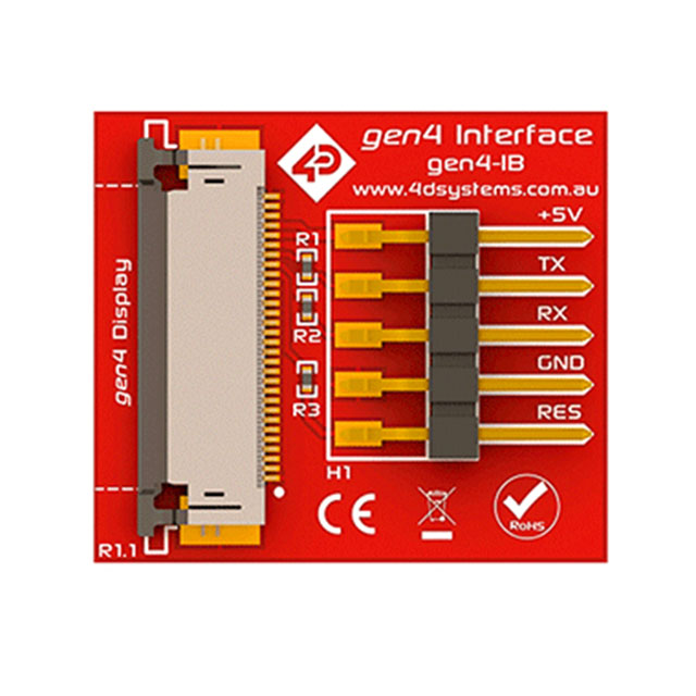
- gen4 -Programming Adapter (3rd image) or gen4 -Interface Board (2nd image)
- uUSB -PA5 (if using gen4-IB) (4th image)
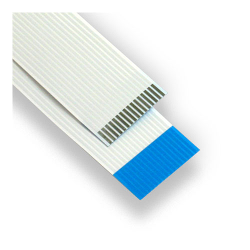
- 30 way FFC Cable
- uSD Card
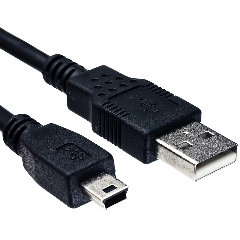
- Mini USB Cable (if using gen4-PA) (8th image) or Micro USB Cable (if using gen4-IB) (7th image)
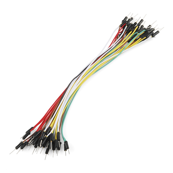
- Connecting Wires
Build

If you are using gen4-IB and uUSB PA-5, connect the display to your computer as shown in the image (1st image)·
If you are using gen4-PA board, connect the display to your computer as shown in the image (2nd image)·
Program


Download the project file here.
You can download Workshop 4 IDE and the complete code for this project from our website.
Open the project using Workshop 4. This project uses the ViSi Environment.
You can modify the properties of each widget.
Click on the “Build Copy/Load” button.
Note: This step could be skipped. However, compiling is essential for debugging purposes.
Connect the display to the PC using uUSB-PA5 and a mini USB cable. Make sure that you are connected to the right port. Red Button indicates that the device is not connected, Blue Button indicates that the device is connected to the right port.
Now click on the “Comp’nLoad” button.
Workshop 4 will prompt you to select a drive to copy the image files to a uSD Card. After selecting the correct drive, click OK.
The module will prompt you to insert the uSD card. (1st image)
Properly unmount the uSD Card from the PC and insert it to the uSD Card slot of the display module. The image below must appear on your display after completing the steps above. (2nd image)
Demonstration


First, set the present date and time. This must be done at first boot or if the device is powered off.
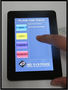
You may now add some plans and you will see your plans for the present day back in the home screen.
Flowchart


