Plasma Sprockets

1. Unlike belts they can transmits large amounts of torque
2. Unlike meshing gears they don't need to be constantly lubricated
3. Unlike belts and mesh-gears the spacing between gear centers can be easily adjusted by shortening/lengthening the chain
However, getting the right size/right pitch gear can be an impossible task for some DIY projects. Specifically, those that require a gear to fit a certain bolt mounting bolt pattern.
The obvious solution when a sprocket gear is wanted, but can’t be found, is to make your own. Historically, this is easier said than done because the two main methods for a DIY to create the high accuracy needed for a sprocket gear is to use a 3D printer or plasma CNC. Both of which have issues given that sprocket gears typically require more strength than can be provided by 3D printers and the warping often caused by plasma cutting creates gears that have an annoying tendency to throw the chain off.
This is where plasma-sprockets enter the scene. I developed these while creating the world's first apocalypse ready solar car, the Apocalypse EV1 (http://www.ApocalypsEV.com). Plasma-sprockets use a radically different multi-piece sprocket design. The unique design sandwiches a chain between two side sections as it rotates about the gear, preventing any warping issues caused by using a CNC plasma cutter.
In addition to creating sprocket gears that can be effectively cut with a CNC plasma table; plasma-sprockets do what no other gear or pulley has done before - allow you to take them on and off the middle of an axle without having to take the axle off. By not having to remove the tires, bearings, and mounting brackets just to change a gear ratio, plasma-sprockets save hours of time and lots of confusion (trust me).
This Instructable covers how to create a virtual plasma-sprocket and then make it into a real part via a plasma CNC table.
Get DraftSight or Other 2D CAD

http://www.3ds.com/products/draftsight/overview
For those who have learned how to use, and are hopelessly addicted to AutoCAD's GUI, I might note that DraftSight has the look and feel of classic AutoCAD without the $4000+ price tag.
NOTE: This instructable only covers how to convert an already drawn sprocket gear into a plasma-sprocket. To learn how to draw a basic sprocket gear and where to get a free CAD program please check out one of my other instructables that covers the topic https://www.instructables.com/id/How-to-Draw-a-Sprocket-Gear/.
Draw the Plasma Sprocket
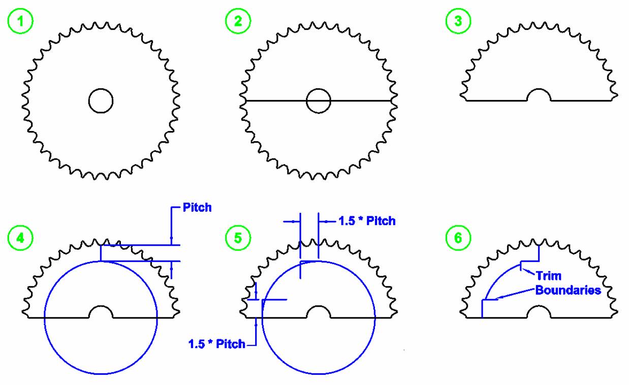
1. Starting with an already drawn sprocket gear that has an even number of teeth (40 tooth #40 chain in this case).
2. Draw a line down the center of the gear making sure that it goes from one tooth valley to another.
3. Use the center line to trim the gear in half.
4. Starting from a valley on the top side of a gear go down the length of pitch and then draw a circle from the center to meet it.
5. At the 90degree mark go out 1.5 times the pitch length and then down past the circle and then at the 180degree mark go up 1.5 times the pitch length and then to the right past the circle.
6. Use the lines extending past the circle as trim boundaries for the circle.
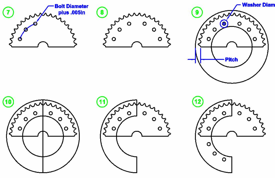
7. At both ends and the center of the arc left by the trimmed circle create three circles with a diameter equal to the diameter of the bolts to be used plus .005in.
8. Mirror those three holes vertically about the center.
9. You will now need to draw to large circles. The first and larger of the two extends from the center out past the edge of the gears tooth valley the length of the pitch. The second extends from the center up to where the outside diameter of the washers for the bolts will be.
10. Draw a vertical line that bisects the larger of the two new circles.
11. Use that vertical line to trim the two new circles into a crescent shape.
12. Mirror the three bolt holes on the left side of the gear horizontally about the center point.
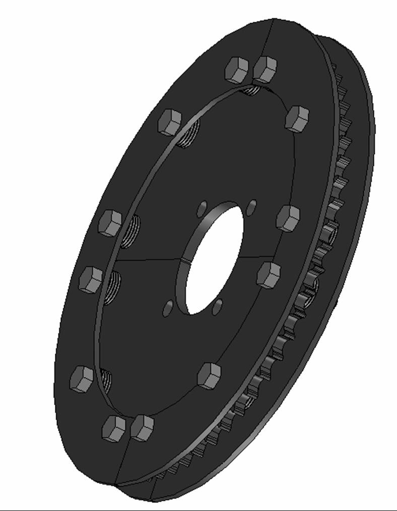
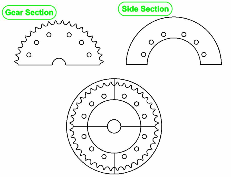
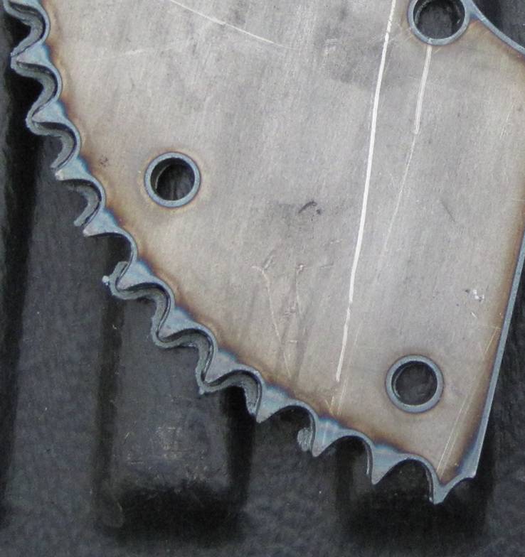
The end result of this process will be the gear section and side section of the plasma-sprockets design that when put together form a completed plasma-sprockets
NOTE: the rule of thumb for determine bolts size is that the bolt diameter should be close to the roller diameter of the gear (5/16in in this case of #40 gear).
Cut the Plasma Sprocket Parts


Notes: I used 1/4in plate for the gears sections and 10GA for the sides sections to create a #40 gear. If you cant find a chunk of material thick enough to create the gear sections, no sweat. Just double up two thinner piece of material. Also the sprocket can afford to be thinner than recommended as the sides keep the chain on track.
Cleanup and Paint the Parts


Bench Sprocket Assemble


1. Do a little experimentation to see how much of a gap is needed between the gear sections and the side sections, noting that there are two sides. Then find combination of washers and/or over-sized nuts that create this spacing on each side.
2. Take two of the sides and place a bolts though them facing upright.
3. Place the one layer of spacers on top of the bolts.
4. Place the two gear sections on top of the side sections noting that the two seams are supposed to be at 90degrees to each other.
5. Place the other set of spacers on top of the gear sections.
6. Place the other two side sections on top of the spacers (A little persuasion from a rubber mallet might be required to line everything up at this time).
7. Put nuts on top of the side sections and then tighten them all gradually with some kind of thread locking.
8. Check that everything lines up correctly.
On Axle Sprocket Assemble


The truly unique aspect of the plasma-sprockets design is its ability to be mounted on an axle without first having to remove the axle. This feature has saved countless hours in my DIY go-kart efforts. In particular it allows me to bypass the often flakey and hard to put back together bearing mounts used on solid rear axle drive designs. So to put a plasma-sprockets on an axle directly, use the following steps...
1. Starting with the empty axle shaft take one of the side sections and stick bolts through it.
2. Carefully place it over the axle and add one set of spacers and then one of the gear sections.
3. Put three bolts and a set of spacers into one of the other side sections and then attach it to the gear section.
4. Add the second set of spacers to the gear and then loosely put on the nuts so that the whole assembly does not fall apart when you flip it over.
5. Flip over the assembly so far and add the second gear section.
6. Take off the nut temporally holding the spacers in place on the first gear section, and then add spacers to the second gear section.
7. Add on the last two side sections.
8. Put nuts on top of the side sections and then tighten them all gradually with some kind of thread locking.
9. Check that everything lines up correctly.