Pluvio! Rain Gauge With Tipping Bucket
by alexpikkert in Circuits > Microcontrollers
1514 Views, 12 Favorites, 0 Comments
Pluvio! Rain Gauge With Tipping Bucket
.jpg)
.jpg)

Does it rain?
I'm not sure... I will check my Pluvio!
In this instructable you can see my tipping bucket rain gauge. It sends the rain information wireless to an ESP01 microcontroller in my livingroom and this information is sent via WiFi to an Adafruit dashboard on the internet.
I used a test circuit to design the final hardware and software for this Rain Gauge.
See: https://www.instructables.com/ESP01-Tester/
Supplies
For the pluvio rain gauge:
3D printer
STL files for the gauge, the holder and the box with cover for the transmitter electronics.
3 mm. diameter rod, length 30mm. (steel, aluminium...)
round neodymium magnet 4x2 mm.
See https://www.printables.com/model/386114-rain-gauge-pluviometer
For the transmitter:
WL102 433MHz Wireless Remote Control Transmitter Module including socket
NE555 oscillator including socket
78L33 voltage regulator
2x capacitor 10 nF
resistor 4k7 ohm
resistor 10k ohm
reed contact
battery 12V 23A/MN21 including holder
PCB 26x15 holes with copper islands 2.54 mm.screw block 2 pin connector 2.54 mm.
ductape to cover the reedswitch
For the receiver:
RX470 433Mhz RF Wireless Remote Control Receiver Module including socket
ESP01 microcontroller including socket
LF33CV voltage regulator
resistor 2k2 ohm
3x resistor 1k ohm
2x resistor 10k ohm
2x capacitor 100uF
1 led 5 mm. blue
1 led 5 mm. red
screw block 2 pin connector 2.54 mm.
tactile pushbutton NO 2.54 mm.
PCB 27x19 holes with copper islands 2.54 mm. (80x50 mm.)
USB charger including cable (disconnect one plug to mount the cable on the screw block)
CH340 3.3V TTL USB Serial Port Adapter (with added reset button) to program the ESP01
MyPluvio.ino sketch (using the Arduino IDE)
Adafruit account with feed and dashboard. (Adafruit IO free version)
Go 3D!
.jpg)
.jpg)


.jpg)
.jpg)
.jpg)
.jpg)
.jpg)
.jpg)
.jpg)
I found a great 3D design for a rain gauge with a tipping bucket.
See https://www.printables.com/model/386114-rain-gauge-pluviometer
I added a holder and a smal box with a cover to mount the Pluvio on my garden fence including the electronic parts for the transmitter. The cover is sealed against the ingress of water with a small rubber band between the cover and the box. I covered the small reed switch with ductape as a protection against water drops.
The bucket is mounted on a metal rod and uses a small round magnet to activate the reed switch.
The 433 MHz Transmitter


.jpg)
.jpg)
.jpg)
.jpg)
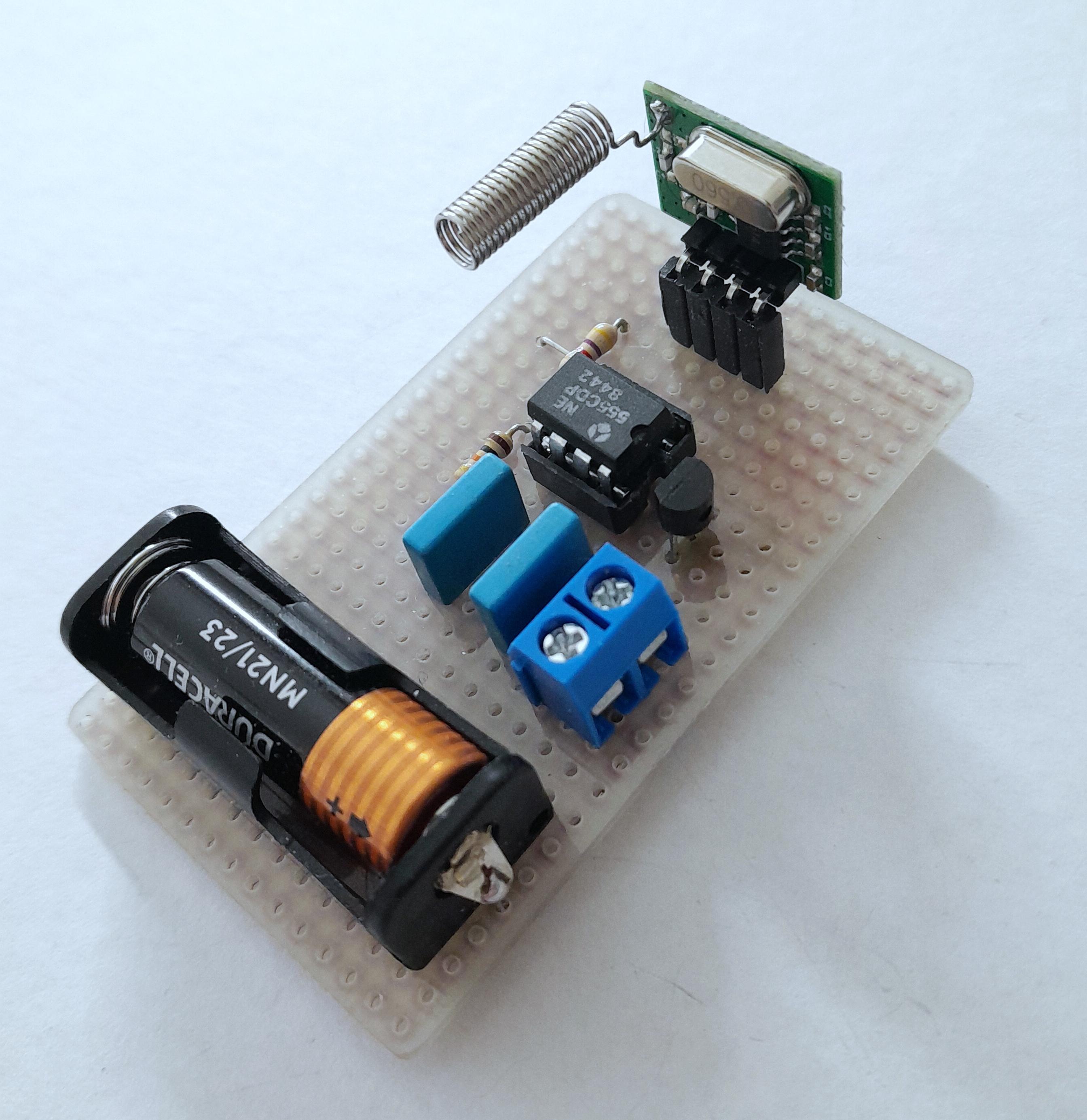
The transmitter uses a WL102 433MHz RF Wireless Module to send a signal to the receiver.
433MHz is a commonly used frequency band for all types of equipment that require little power, such as garage door openers, headphones, baby phones and remote controls. Also many inexpensive transmitters and receivers for switching devices and light dimmers operate on the 433MHz band.
When experimenting with the 433 MHz wireless signals for my Pluvio I found that there is a lot of interference and noise in this area. During testing I connected a small audio amplifier and I heard a lot of beeps, cracks and hissing on this frequency band. The temperature meter from my neighbour transmitted a signal every 30 seconds.. I did not want to receive this wrong information so I used a clean pulstrain of 6kHz generated with an NE555 chip, connected to the transmitter. This signal is filtered out of the noises with the software in the receiver. It works really well, the receiver did not react on the disturbances at all.. The transmitter is switched on together with the NE555 oscillator via the reedswitch. This happens only a short time when the bucked tips. When the bucked is not activated both are completely switched off so there is no constant power needed from the battery.
The specification for the minimum voltage of the NE555 is 4.5 Volt. But my Pluvio NE555 works fine with 3.3 Volt.
The 433 MHz Receiver and the WiFi Connection


.jpg)
.jpg)
The receiver uses an RX470 433Mhz RF Wireless Module.
The output is connected to the input of the ESP01 via a voltage divider with two resistors. This is done because the receiver voltage level is 5V and the ESP01 needs 3.3 Volt on the input pin. The PCB has a connection for 5 Volt power supply (connected to a standard USB charger). Plug the cable into the charger and cut the plug on the other end to connect the red and black wire to the screw block for the power supply. The receiver is connected to this voltage and the ESP01 is connected via a 3.3 V voltage regulator. A red led shows the presence of power, a blue led lights up when a 6kHz signal is received. The receiver and the ESP01 are both mounted on a socket for easy exchange if something goes wrong.
Reset of the ESP01 is done with a tactile switch on the PCB.
Program!


An ESP01 microcontroller can be programmed with the Arduino IDE (Integrated Development Environment).
To download and install the IDE see here: https://www.arduino.cc/en/software/.
But the standard IDE program must first be updated by adding the neccessary board information for the use of an ESP01 microcontroller.
You need basic knowledge of the Arduino system to do this. Don't worry, there is an exellent instructable available with all details how to add this information to a standard IDE:
See https://www.instructables.com/Getting-Started-With-Esp-8266-Esp-01-With-Arduino-/
In this instructable you can also read how to use the CH340 3.3V TTL USB Serial Port Adapter to connect the ESP01 to the USB port of your computer. This adapter needs to have an additional reset button for easy programming, the mounting of this extra button is also described.
To make the rain data available on the internet you can use a free account from Adafruit IO. You will get a user name and you will get a special IO key code to get access to your data. Keep this info in a safe place.
To use the IDE with Adafruit IO you also need the Adafruit IO library. You can install this library in the IDE library manager or download it here: https://github.com/adafruit/Adafruit_IO_Arduino
On the Adafruit IO website you must make a "feed" definition and you can also make a dashboard with a table and/or a graphical presentation of yor rain data. 10 feeds and 5 dashboards are included in a free account.
This information can also made visible for others without exposing your account information.
See here for all details: https://io.adafruit.com/
or here:: https://learn.adafruit.com/adafruit-io-basics-esp8266-arduino/using-arduino-ide
Before uploading the MyPluvio_V1 sketch to your ESP01 you must change a few lines to add the SSID and network password of your own WiFi and the username and IO key from your Adafruit IO account. Just change the text between the brackets:
// WiFi settings
#define WIFI_SSID "your wireless network name (SSID)"
#define WIFI_PASS "your wireless network password"
// Adafruit IO settings
#define IO_USERNAME "your Adafruit IO account user name"
#define IO_KEY "your Adafruit IO key"
There is also a line where you can change the time period between each rain feed sent to Adafruit:
I programmed feeds each hour:
unsigned long interval = 3600000; // 1 hour between each feed update sent to the internet.
Change this value to get a different timing (the value must be in milliseconds)
Remove the // before one of these lines here to change the time period after which the rain value is reset to zero:
//unsigned long interval1 = 2592000000; // after 30 days
unsigned long interval1 = 604800000 ; // after 1 week
//unsigned long interval1 = 86400000; // after 24 hours
//unsigned long interval1 = 43200000; // after 12 hours
The feed factor calculation I used:
1 feed is the amount of rain volume in mm3 per tipping divided by the surface of the gauge in mm2.
rain volume per tipping is 2.5 cm3 (2500 mm3).
gauge surface: the diameter is 110 mm. the radius is 55 mm.
the surface is pi x square radius: 3.14 x 55 x 55 = 9503 mm2
tippingFeed is volume/surface: 2500/9503 = 0.263.
On powering up the receiver the ESP01 will first try to connect to the WiFi network and the Adafruit IO website.
When these connections are OK the blue led will flash three times to confirm.
When the Adafruit IO connection is lost the software will try to reconnect automatically.
Downloads
Additions

My Pluvio is mounted near a few large trees so some small leaves were blocking my funnel....
I places a small sieve inside the funnnel to avoid this blocking.
Regular checking the Pluvio is also a good idea, a few spiders thought they could live inside it and were blocking the tipping bucket with their little web...