PocketPill — a Pocket-Size Smart Pillbox That Blinks & Vibrates So You Never Miss a Dose
by PriyankTyagi in Circuits > Microcontrollers
623 Views, 5 Favorites, 0 Comments
PocketPill — a Pocket-Size Smart Pillbox That Blinks & Vibrates So You Never Miss a Dose

.jpeg)
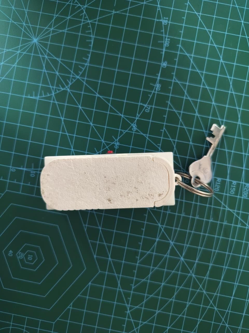
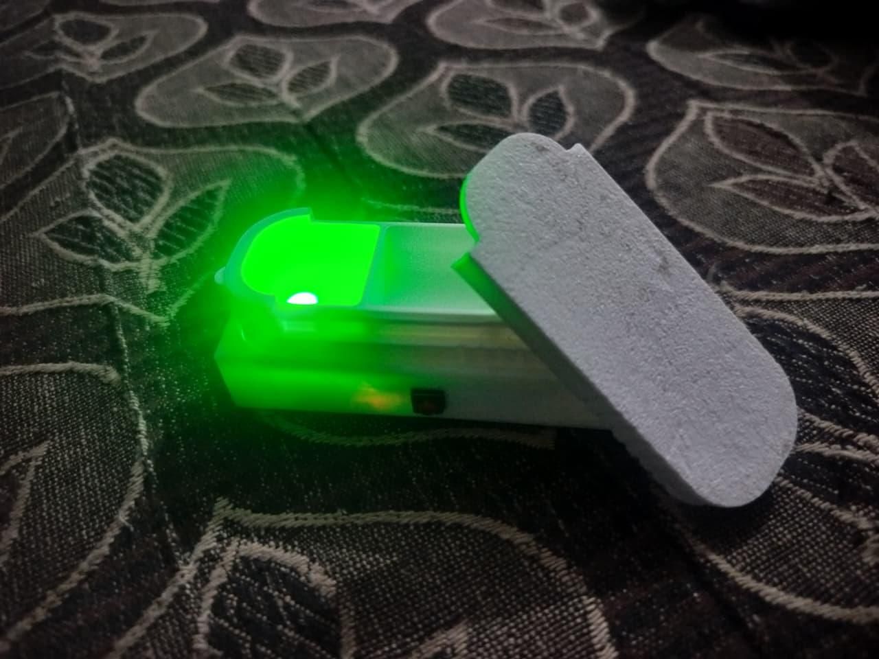
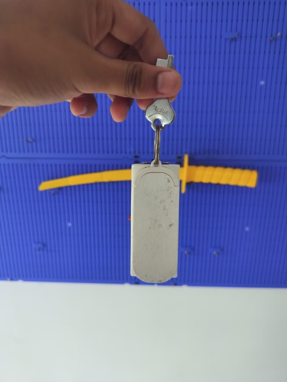
I was diagnosed with TB, and the treatment only works if you take the medicine on time, every single day, without gaps. That sounds simple until you're actually living it — some days I forgot the dose itself, other days I remembered the dose but forgot to carry the pillbox with me, and either way the result was the same: a missed dose. I looked for something small enough to always have on me that would actually remind me at the right time, and back then I couldn't find a single device built for this — just bulky organizers meant to sit on a shelf, not travel in a pocket. So I built PocketPill: something small enough to carry every day, that reminds me until I actually respond to it, and that I can set up myself from any phone in two minutes — no login, no app, nothing to install.
Most pill reminders fail for one simple reason: they stay at home while you don't. Phone alarms get swiped away. Big weekly organizers sit on the kitchen table.
PocketPill fixes this differently than most reminder projects: instead of hard-coding a schedule into the firmware, the box itself is the settings page. It broadcasts its own WiFi hotspot — connect your phone to it, open one webpage, and set your dose times and colors right there. No app to install, no companion account, no cloud service that can go offline.
- 🔴 Blinks + vibrates in your pocket when a dose is due — with a color you pick per dose
- 📶 Configure it from any phone — connect to its WiFi hotspot, open 192.168.4.1, set times and colors
- ⏱️ Escalates — pulses faster and more urgently the longer you ignore it
- ✋ Hold the button 3 seconds to silence an alarm
- 🔋 USB-C rechargeable 400mAh LiPo
- 🗝️ Hangs on your keychain, sliding tray with 3 compartments
Built from cheap, common modules — no custom PCB, no cloud account — so anyone with a 3D printer and a soldering iron can make one in a weekend.
Supplies
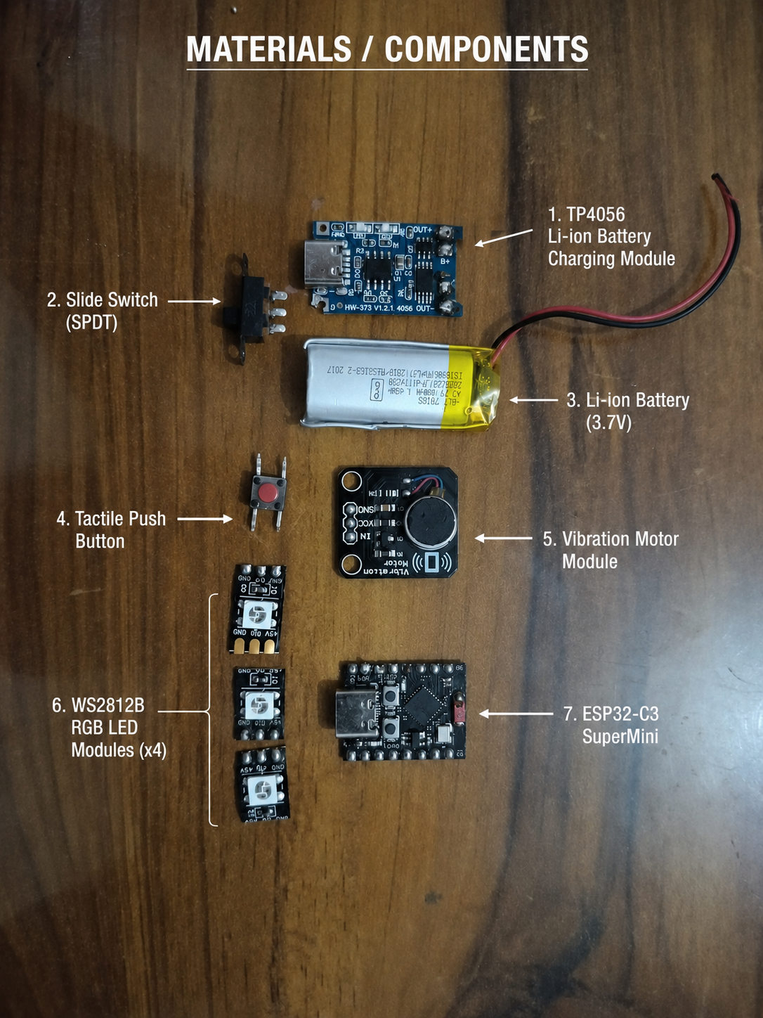
Electronics:
- ESP32-C3 SuperMini development board (×1)
- TP4056 USB-C LiPo charger module, HW-373 type with protection (×1)
- 3.7V 400mAh LiPo battery, 401635 size (×1)
- Vibration motor module (coin motor on driver breakout) (×1)
- WS2812B addressable RGB LEDs — 3 pixels cut from a strip, or 3 breakout boards (×3)
- Tactile push button 6×6mm (×1)
- Slide switch (×1)
- Thin hookup wire (30 AWG silicone wire works great)
- 2 small self-tapping screws
- Split ring / keychain ring
Tools:
- 3D printer (I used a Bambu Lab A1 mini) + white PLA (white matters — it diffuses the LED glow beautifully)
- Soldering iron, solder, flux
- Hot glue or double-sided tape
- Wire strippers, side cutters
Software:
- Arduino IDE (or PlatformIO) with ESP32 board support
- Adafruit NeoPixel library
- Bambu Studio (or any slicer)
How It Works (The Design)
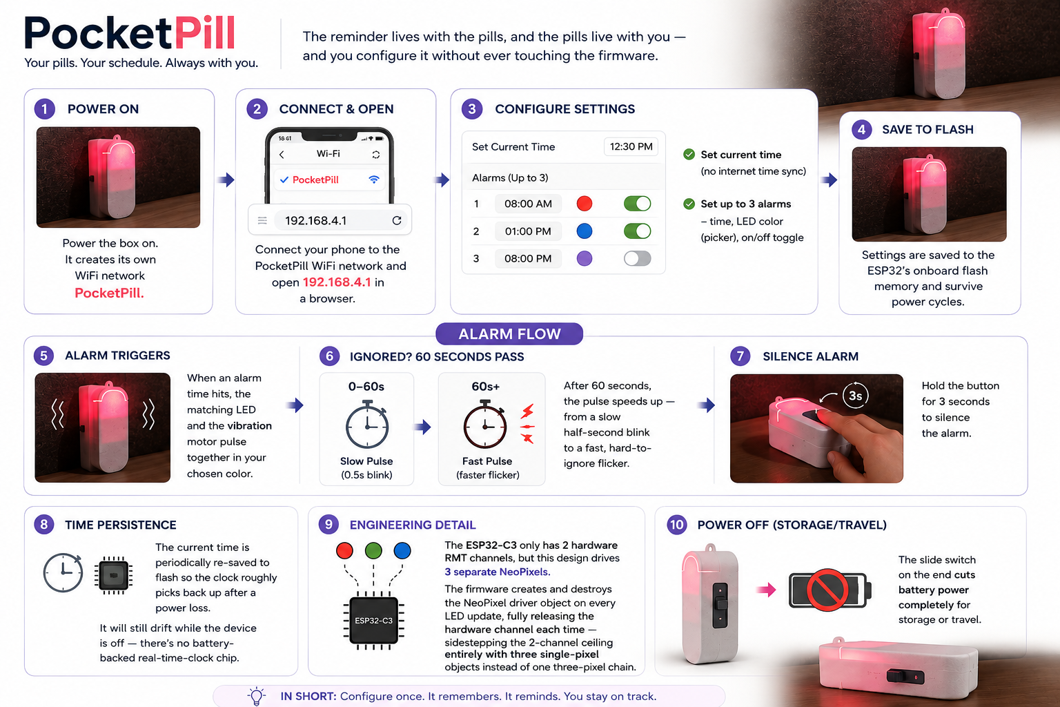
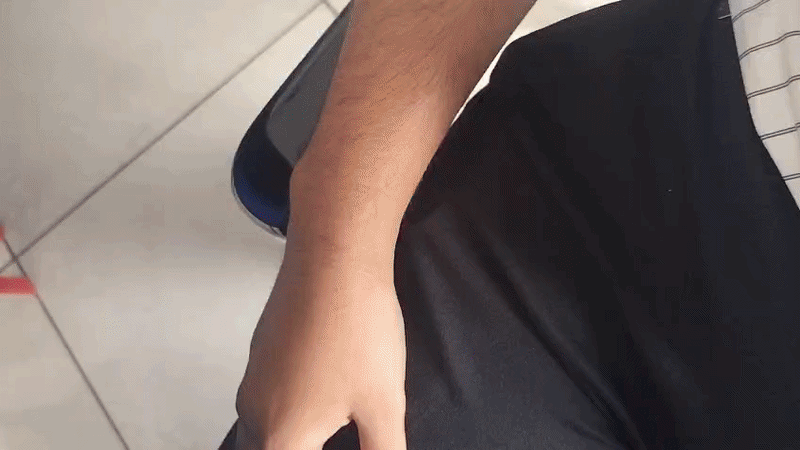
The concept: the reminder lives with the pills, and the pills live with you — and you configure it without ever touching the firmware.
Here's the actual flow:
- Power the box on. It creates its own WiFi network called PillBox.
- Connect your phone to that network and open 192.168.4.1 in a browser.
- A simple page lets you: set the current time (there's no internet time sync — you set it once by hand), and set up to 3 alarms, each with its own time, its own LED color (color picker), and an on/off toggle.
- Those settings are saved to the ESP32's onboard flash memory, so they survive a power cycle. The current time is also periodically re-saved so the clock roughly picks back up after a power loss, though it will still drift while the device is off — there's no battery-backed real-time-clock chip.
- When an alarm time hits, the matching LED and the vibration motor pulse together in your chosen color.
- Ignore it? After 60 seconds, the pulse speeds up — from a slow half-second blink to a fast, hard-to-ignore flicker.
- Hold the button for 3 seconds to silence the alarm.
One engineering detail worth calling out to judges: the ESP32-C3 only has 2 hardware RMT channels, but this design drives 3 separate NeoPixels. Rather than fight that limit with a workaround library, the firmware creates and destroys the NeoPixel driver object on every single LED update — which fully releases the hardware channel each time, sidestepping the 2-channel ceiling entirely with three single-pixel objects instead of one three-pixel chain.
The slide switch on the end cuts battery power completely for storage or travel.
3D Print the Case
.jpeg)
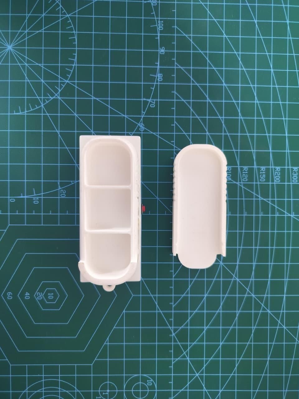
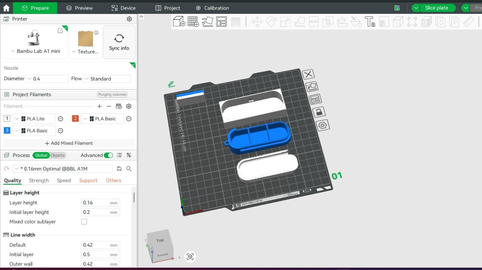
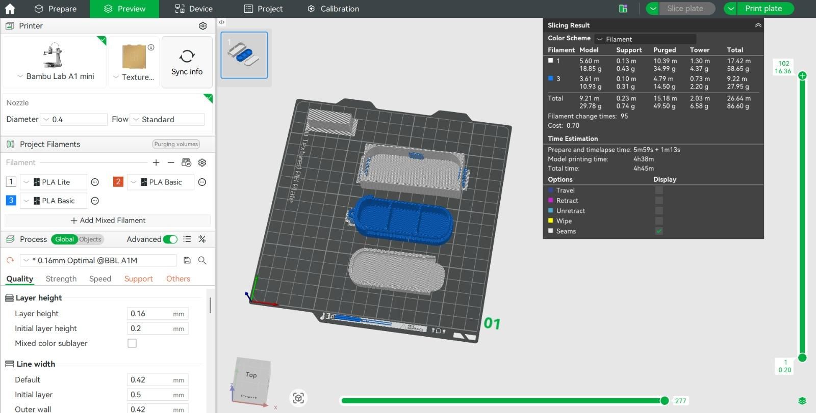
The case is three printed parts (all STLs attached above — download and slice):
- Box.stl — Main shell. Houses all the electronics, with cutouts for USB-C charging, the side button, the end slide switch, and a keychain loop on top.
- PILLBOX.stl — Sliding pill tray with three compartments. Rides on rails above the electronics bay.
- Capsule+Logo.stl — Lid, with an embossed capsule logo on top. Slides over the tray to keep the pills secure.
I designed all three parts in Autodesk Fusion 360. Fusion made it easy to iterate on the sliding-rail tolerances and cutout positions until the electronics fit snugly and the tray slid smoothly.
Print settings:
- Printer: Bambu Lab A1 mini
- Slicer: Bambu Studio, using the 0.16mm Optimal @BBL A1M profile
- Material: white PLA — this is not optional. White PLA at 2–3 walls acts as a light diffuser, which is why the whole box glows softly when an LED lights up inside, instead of just a pinpoint of light escaping. Any other color will kill the effect.
- Layer height: 0.16 mm
- Walls: 2–3 perimeters, ~15% infill
- Supports: minimal — the openings face outward, so only the keychain loop needs a small support
- Print time: ~4 h 45 min for all three parts together
- Filament used: ~27 g (about $0.70 worth)
The whole print fits comfortably on the A1 mini's 180 × 180 mm bed with room to spare. If you're on a larger printer, you can print multiple boxes side by side.
Prepare the Electronics
.jpeg)
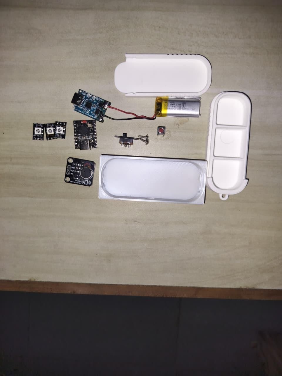
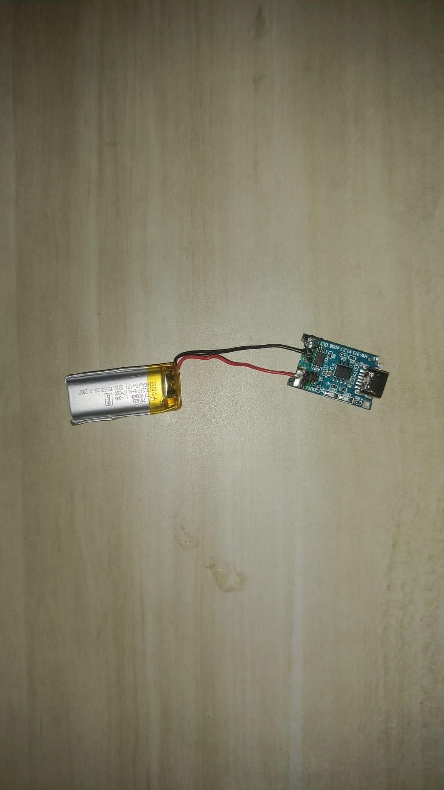
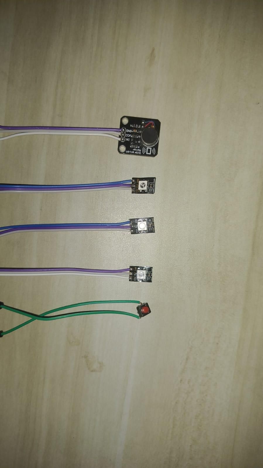
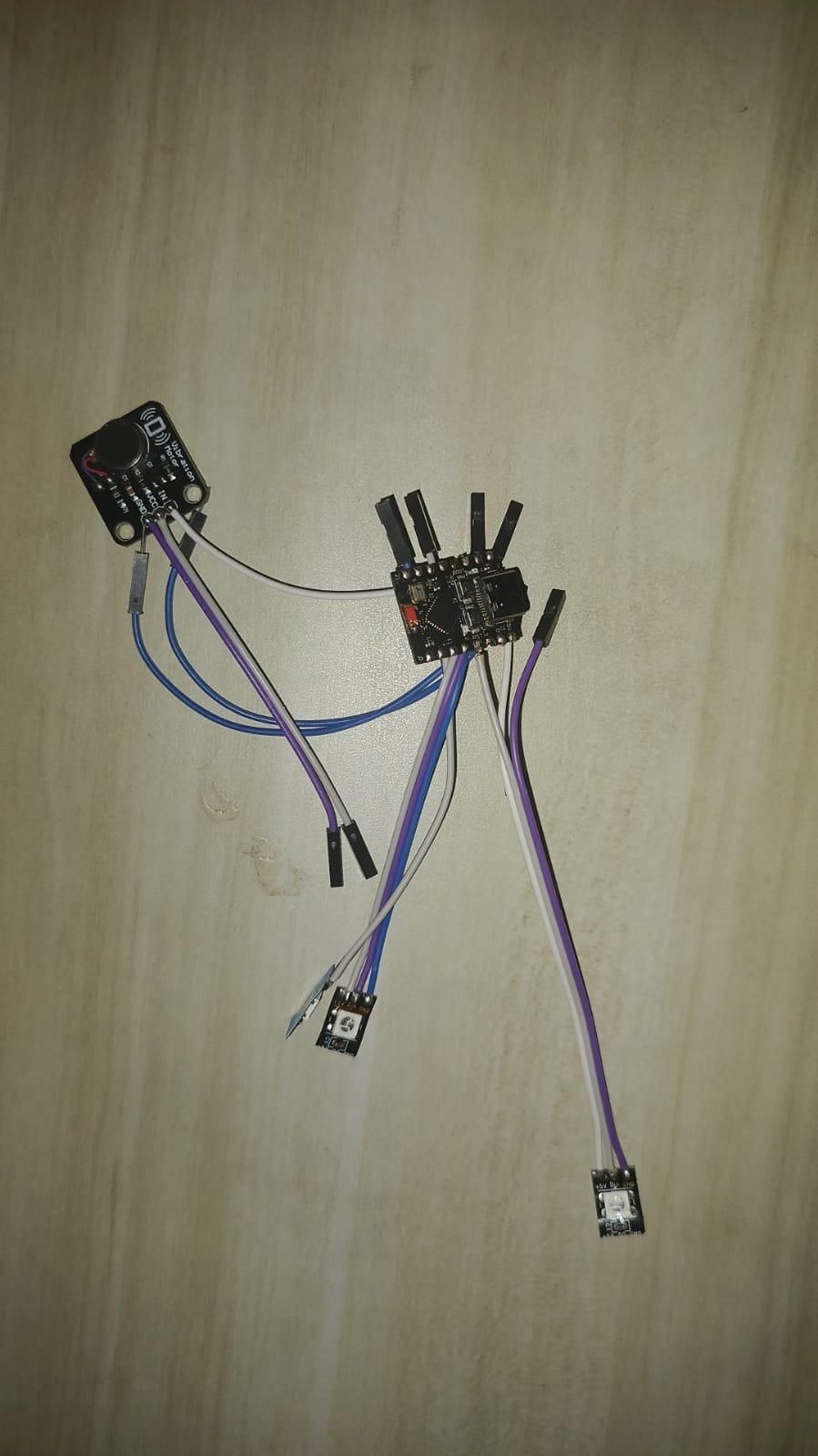
Before wiring everything together, each module needs a bit of prep. Work through them in this order and you'll have a tidy pile of "ready-to-install" parts by the end.
LEDs (3× WS2812B pixels). Each pixel is wired independently — its own 5V, GND, and DIN running straight back to its own GPIO on the ESP32. They are not chained pixel-to-pixel the usual way. This matches how the firmware drives them (three separate RMT channels, one per pixel — see Step 5). It uses a few extra wires, but it makes the code simpler and each compartment fully independent.
Vibration motor module. No prep needed. The board has a driver transistor on it already, so it takes three connections: VCC, GND, and IN (signal from the ESP32).
Push button. Solder two thin wires to the tactile button — one leg goes to a GPIO, the other to GND. No pull-up resistor needed; the firmware enables the ESP32's internal pull-up.
TP4056 charging module. Solder the LiPo battery's leads to B+ (red) and B− (black) on the board. Double-check polarity before powering anything on — a reversed LiPo will damage the module and can damage the cell. Everything else in the circuit draws power from OUT+ and OUT−, not directly from the battery, so the TP4056's protection circuit can cut power if the cell gets too low.
Slide switch. Sits in series between OUT+ and the rest of the circuit, so flipping it disconnects battery power completely. Useful for shipping, storage, or hard-resetting the box.
⚠️ LiPo safety. Lithium-polymer cells are safe when treated with respect, but they don't forgive mistakes. Never short the battery leads together, never pierce or crush the cell, and only ever charge it through the TP4056 module — never directly from a bench supply. If the cell ever puffs up, gets hot, or smells sweet, stop using it and dispose of it properly.
Wiring
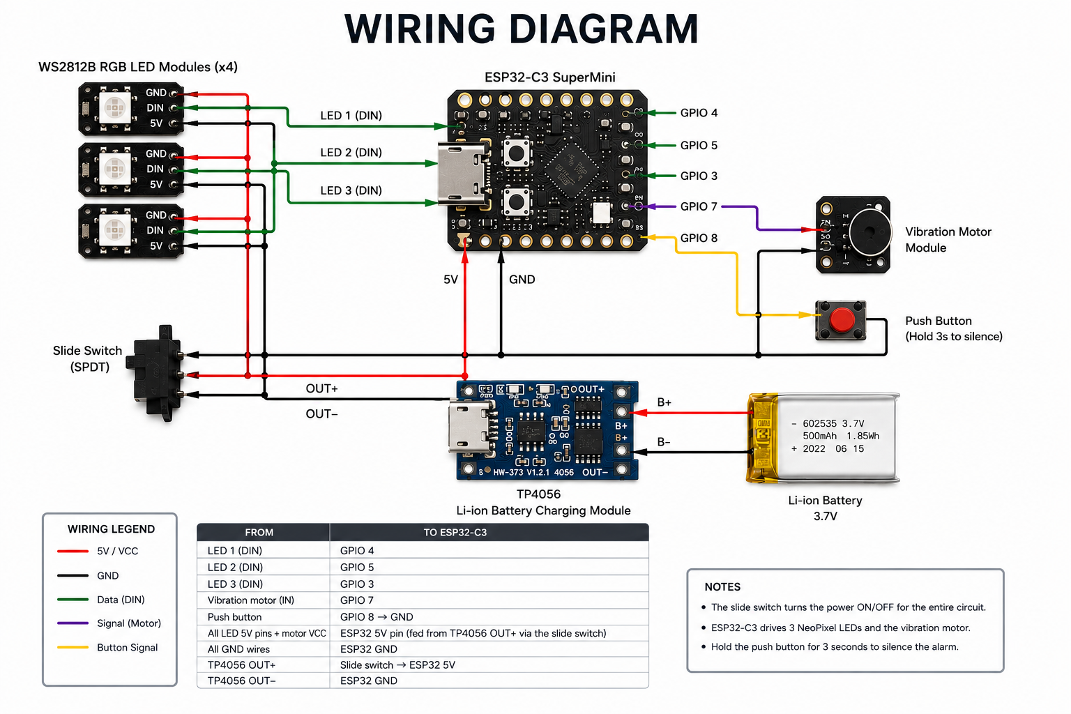
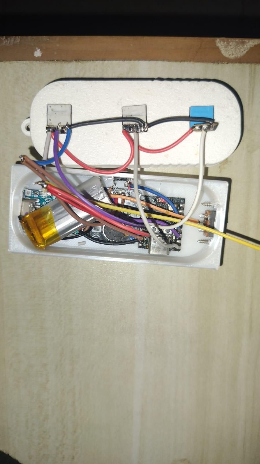
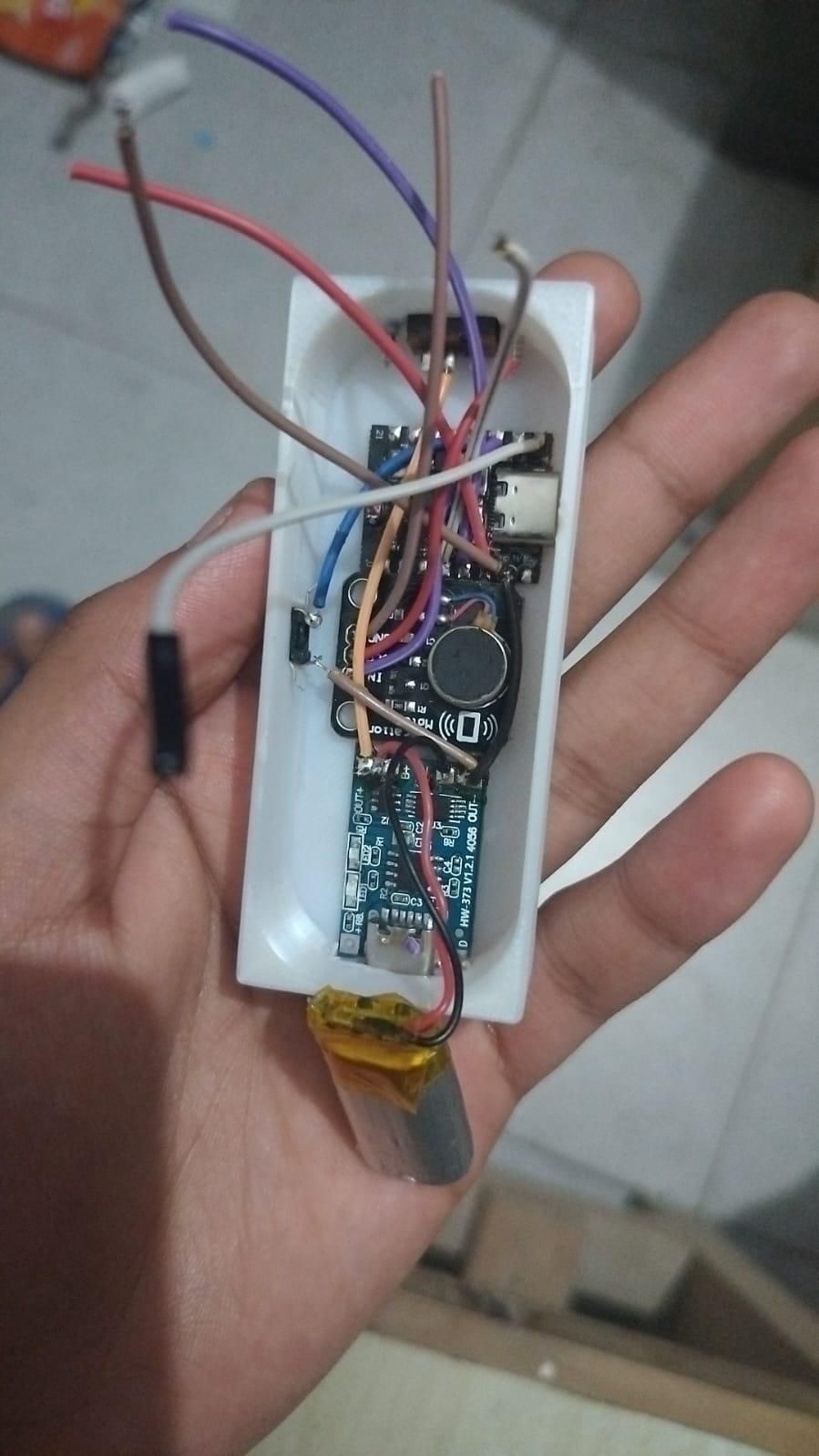
With every module prepped, wiring is quick. Here's the full pin map:
From To ESP32-C3
LED 1 (DIN) GPIO 4
LED 2 (DIN) GPIO 5
LED 3 (DIN) GPIO 3
Vibration motor (IN) GPIO 7
Push button GPIO 8 → GND
All LED 5V pins + motor VCC ESP32 5V pin (fed from TP4056 OUT+ via the slide switch)
All GND wires ESP32 GND
TP4056 OUT+ Slide switch → ESP32 5V
TP4056 OUT− ESP32 GND
The WS2812B pixels and vibration motor run happily from the LiPo's ~3.7–4.2V on the 5V rail. The ESP32-C3 SuperMini's onboard regulator drops that to the 3.3V the chip actually needs.
⚠️ Heads up if you rewire this to different pins. GPIOs 4, 5, 6, and 7 on the ESP32-C3 are also the default JTAG debug pins. On boot, the JTAG controller grabs them and the LEDs on those pins will misbehave until it lets go. The firmware works around this by explicitly setting GPIOs 3, 4, and 5 to OUTPUT at startup, which detaches JTAG. If you swap to any pins in the JTAG range on your own build, do the same — otherwise you'll spend an hour chasing phantom LED behavior. Ask me how I know.
Assembly
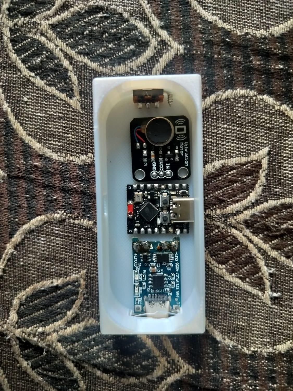
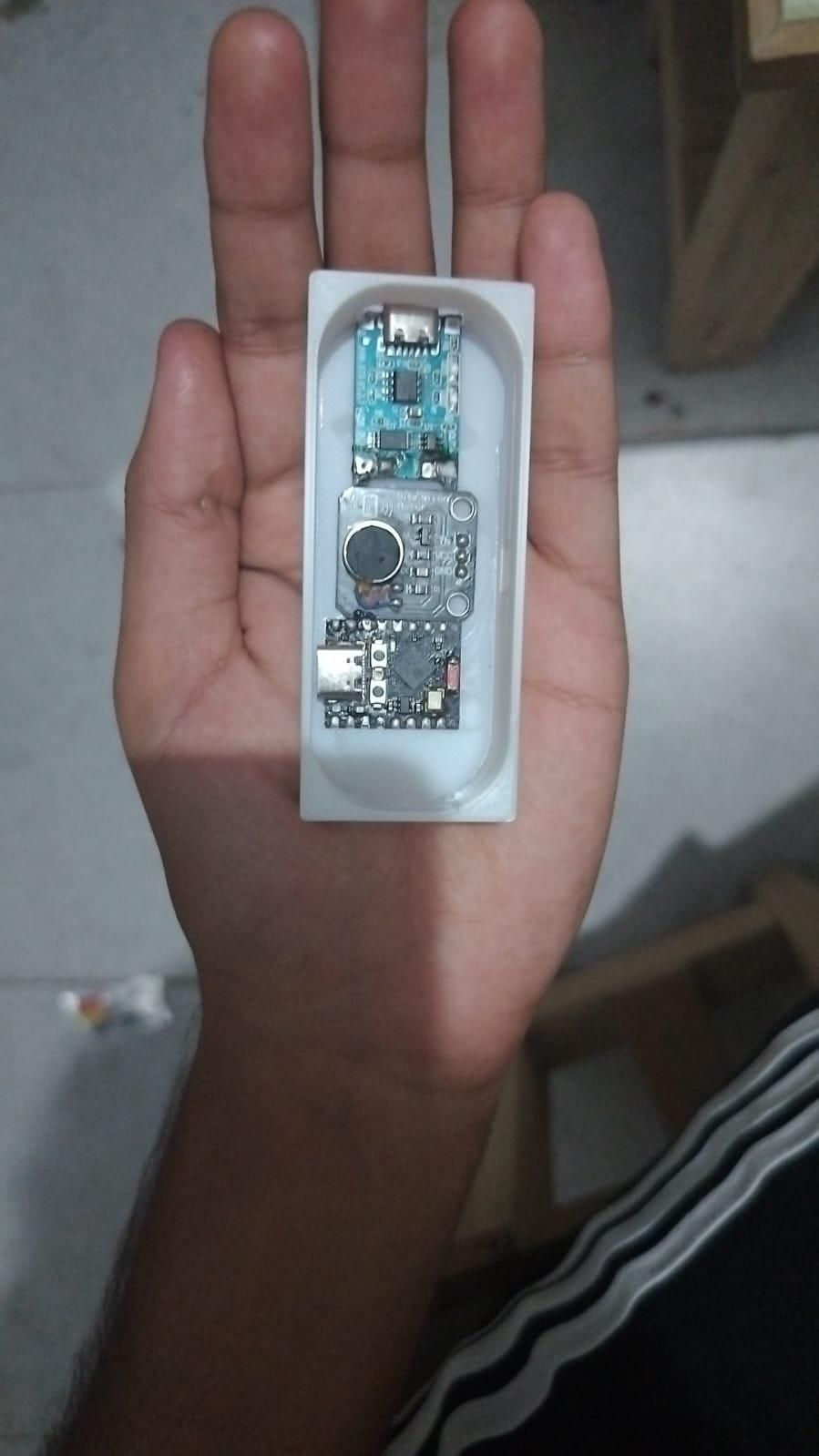
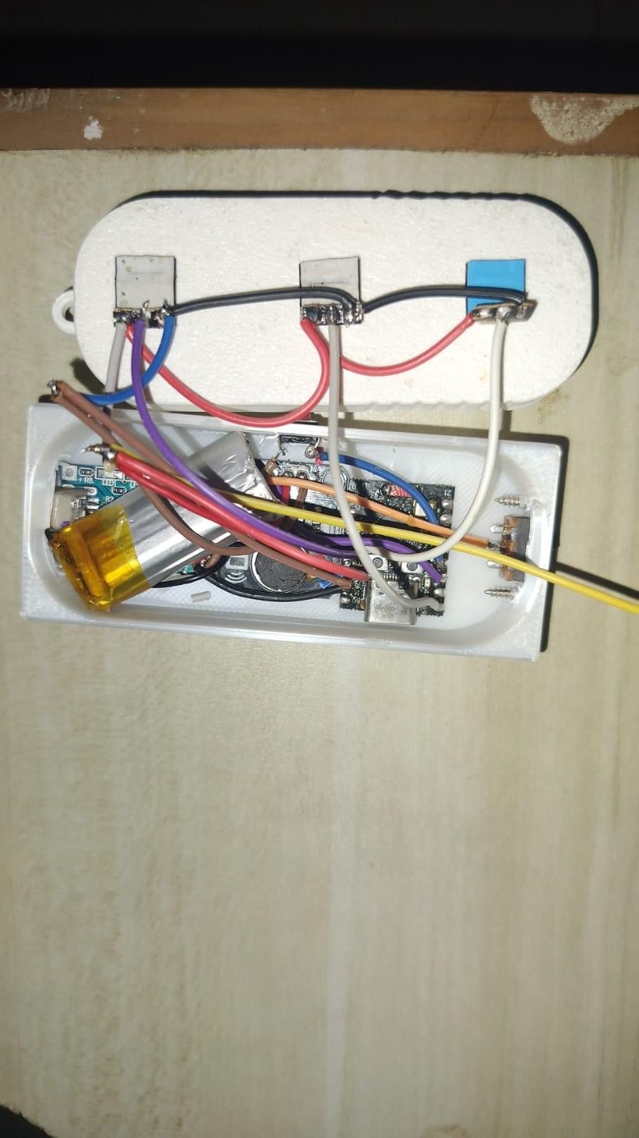
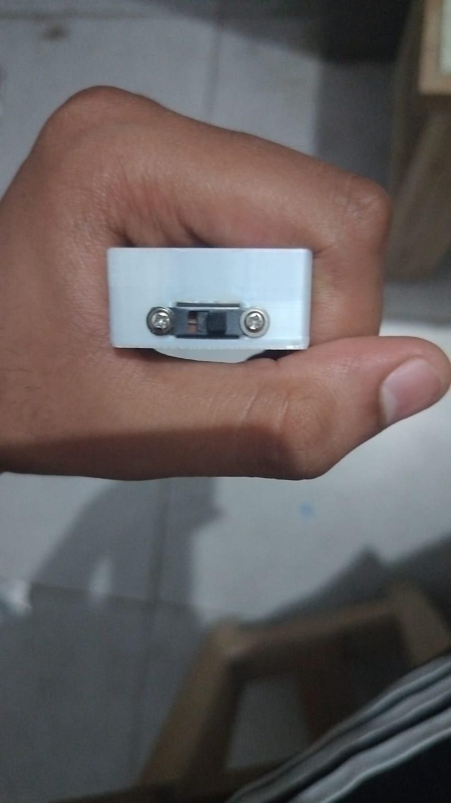
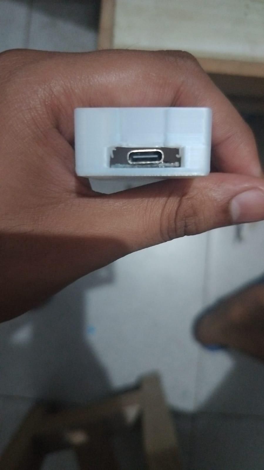
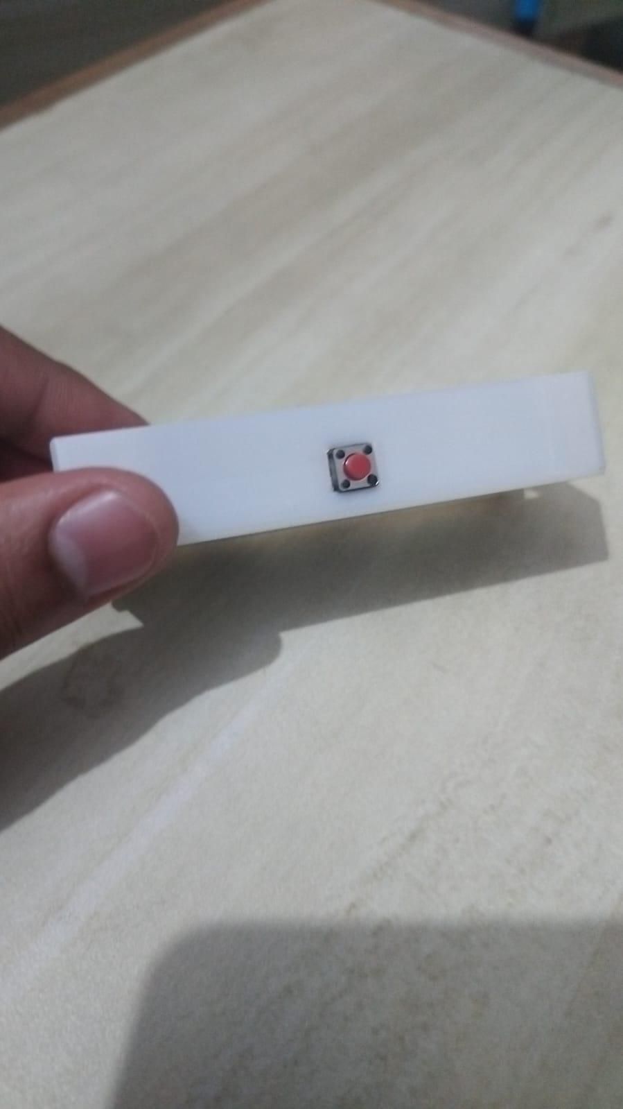
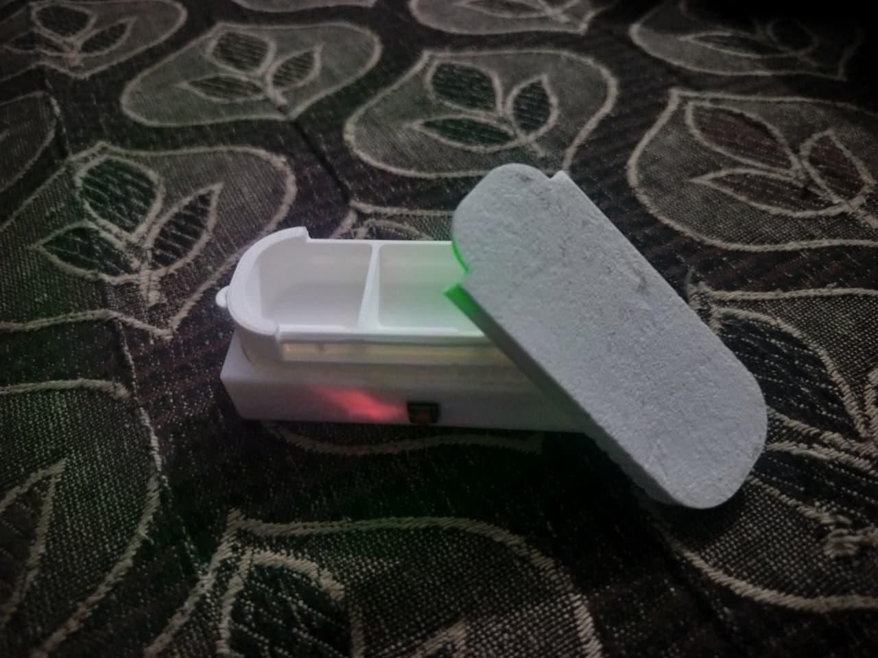
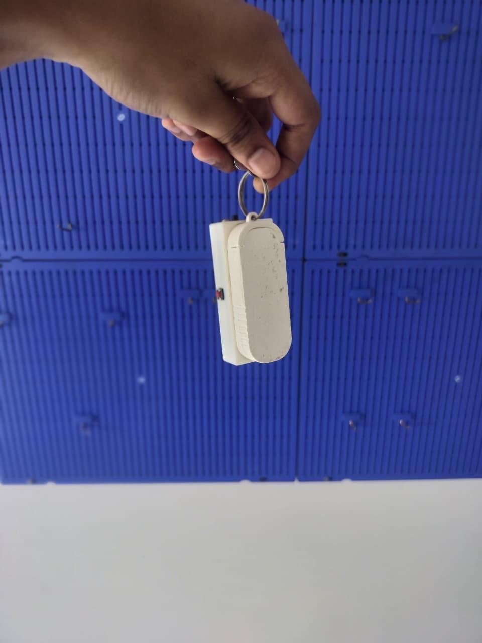
Everything's prepped, everything's wired, everything's tested. Time to close it up.
The design is clean: everything electronic lives inside one sealed bay at the bottom of the case. The 3 pill compartments sit directly above it, separated by the printed shell wall. The 3 LEDs point up into that wall, and the white PLA diffuses the light so each entire pill compartment glows softly in its chosen color when an alarm fires. Only the USB-C port and push button are exposed to the outside. Pills never contact electronics.
Before you start gluing anything down, do a final power-on test with everything still loose: flip the switch, connect to the PillBox WiFi from your phone, load 192.168.4.1, and trigger a test alarm on each of the 3 LEDs. It is far easier to re-solder a dead pixel now than after everything is glued in.
Assembly order:
- Slide switch — mount it into the end cutout of the shell first, secured with the two small self-tapping screws. Doing this first gives you a stable anchor to route the battery wire from.
- TP4056 charging module — sits at the bottom of the electronics bay with its USB-C port aligned to the case cutout. Fix it with a small dab of hot glue on the underside. Plug in a USB-C cable before the glue sets to verify port alignment — a misaligned charge port is the one mistake you can't easily fix later.
- ESP32-C3 SuperMini — sits in the middle of the bay. Its own USB-C aligns with a second opening, so you can re-flash the firmware anytime without opening the box. Hot-glue the underside once the port lines up.
- Vibration motor module — mounts inside the bay, pressed firmly against the shell wall. That wall contact is what transmits the buzz to the whole case — if the module floats freely on wires the vibration feels weak and muffled in a pocket. Hot glue holds it in position.
- The 3 WS2812B pixels — position one under each of the 3 pill compartments, LEDs pointing up into the shell wall. Small squares of double-sided tape hold each pixel flat against the top of the electronics bay. Route their signal wires back to the ESP32 through the gaps between modules.
- Push button — press-fits into the side hole in the shell. If the fit is loose, a tiny drop of glue on the flange keeps it seated.
- LiPo battery — tuck it in last, along one side of the electronics bay. A small strip of double-sided tape stops it from rattling around, but don't compress or bend the cell. Route its leads to the TP4056 with slack — no tension on the solder joints.
Once everything is in:
- Cable-manage. Push all wires flat against the bottom of the bay so nothing bulges up into the pill compartments. This is fiddly but important — anything sticking up will foul the sliding tray above.
- Slide the pill tray onto its rails and confirm it moves smoothly. If it catches, a stray wire is probably in the way — go back and re-route it.
- Fit the lid on top of the tray.
- Add the keyring through the loop at the top of the shell.
Give the box a final shake — nothing should rattle. Plug in USB-C to confirm the TP4056's red charge LED lights up. Then trigger a test alarm through the web page. If the whole box glows and buzzes in your hand, you're done — pocket it and move to the next step.
The Code
.jpeg)
Here's the firmware in full. Flash it once and the box is fully self-contained — no home WiFi, no internet, no cloud accounts.
What it does:
- Boots as its own WiFi Access Point — network name PillBox, password 12345678. No home WiFi credentials to enter, no internet required. Connect from any phone, tablet, or laptop.
- Serves a config page at 192.168.4.1 for setting the clock and configuring 3 independent alarms — each with its own time, its own LED color (full color picker), and an on/off toggle.
- Saves everything to flash memory using the ESP32's Preferences library — settings and the current time survive a power cycle. The time is auto-saved every 10 minutes, so after a power loss the clock picks up close to where it left off.
- Checks the clock every second. When an alarm's time arrives, the matching compartment LED pulses in your chosen color and the vibration motor pulses in sync.
- Escalates when ignored. For the first 60 seconds it pulses gently at 500 ms intervals. After that, it speeds up to 150 ms — harder to sleep through, harder to ignore.
- Hold the button for 3 seconds to silence the active alarm and go back to standby.
Libraries you'll need (install via Arduino IDE's Library Manager):
- Adafruit NeoPixel — drives the WS2812B pixels
- Preferences, WiFi, and WebServer — bundled with the ESP32 board package, no separate install
Board setup in Arduino IDE:
- Board: ESP32C3 Dev Module
- USB CDC On Boot: Enabled (lets you see Serial output over the same USB-C you flash with — trips up a lot of ESP32-C3 first-timers)
- Flash Size: 4MB
- Upload Speed: 921600
Two engineering decisions worth calling out — if you're reading the code to learn, these are the interesting bits:
1. Driving 3 WS2812B pixels on 3 separate pins on the ESP32-C3. The ESP32-C3 only has 2 RMT hardware channels, but the standard Adafruit NeoPixel library needs one RMT channel per strip. Normally that would cap you at 2 independent LEDs. The workaround here: I create the Adafruit_NeoPixel object inside the setLED() function as a local variable. When the function returns, the object is destroyed, which releases the RMT channel, so the next call can grab it again. It's slightly wasteful of CPU time (~5 ms per LED update), but the box spends 99.99% of its time doing nothing, so it doesn't matter — and it lets each pill compartment have its own independent GPIO. Look for the comment in setLED().
2. Detaching the JTAG debugger from GPIOs 3, 4, 5, 7. On the ESP32-C3, GPIOs 4–7 are the default JTAG debug pins, and the JTAG controller holds onto them at boot. If you just call neoPixel.begin() on those pins, nothing works. The fix is explicit pinMode(pin, OUTPUT) at the very top of setup() — that forces the JTAG controller to release the pins. See the first few lines of setup(). Ask me how many hours I spent finding this out.
The firmware:
(I've also attached the raw .ino file at the top of this Instructable — download that instead of copy-pasting to avoid any curly-quote or hidden-character issues.)
First-time setup after flashing:
- Flip the slide switch on. The onboard LED on the ESP32-C3 will confirm it booted.
- On your phone, open WiFi settings and connect to the network PillBox with password 12345678.
- Your phone will warn that "this network has no internet" — that's expected. Tap Stay connected or Use anyway.
- Open a browser and go to 192.168.4.1.
- Set the current time, then configure your alarms (time, color, on/off) and hit save.
- That's it — disconnect and pocket the box. It'll fire the alarms right on schedule.
Downloads
Battery Life
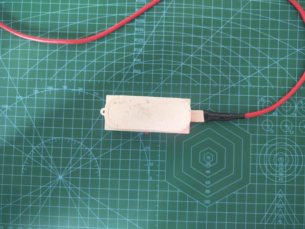
This is a battery-powered contest, so let's talk battery honestly — with real numbers and the reasoning behind them.
The battery. A single-cell LiPo, 400 mAh at 3.7 V nominal — about 1.48 Wh of stored energy. Real-world usable capacity is around 85% of nameplate (the TP4056's protection circuit cuts off well before the cell is drained flat), so plan on ~340 mAh usable per charge.
The design decision. The hungriest component in this box, by far, is the WiFi radio — roughly 90 mA whenever it's broadcasting. So the firmware treats it as a luxury, not a default: the Access Point runs for 5 minutes after boot (or after a button press) so you can configure your alarms, then shuts itself off automatically. Press the button once and it comes back — LED 1 blinks blue to tell you the network is live. The rest of the time, the radio stays dark and the chip just quietly keeps the clock and watches for alarm times.
Where the energy actually goes:
- Idle, WiFi off (the vast majority of the day): ~20–25 mA — the ESP32-C3 running its clock loop with the radio powered down
- Alarm active (LED + motor pulsing): ~150 mA, but only ~90 seconds a day across 3 alarms — about 4 mAh/day, a rounding error
- WiFi config mode: ~90 mA, but only when you've pressed the button to change something — negligible once the box is set up
The math:
340 mAh usable ÷ ~23 mA average ≈ ~14 hours per charge
What that means in practice: treat PocketPill like wireless earbuds, not like a watch. It comfortably covers a full waking day — morning dose to night dose — then goes on the charger while you sleep. USB-C from any phone charger fills it empty-to-full in under an hour, so the routine is one habit: pocket it in the morning, dock it at night.
Where v2 goes. The next big win is true deep sleep between alarms — dropping idle draw from ~23 mA to ~40 µA, a 500× reduction. Same battery, same wiring, roughly two months per charge. The hardware already supports it; it's purely a firmware rewrite, and it's at the top of my v2 list. For v1, the always-simple "press button, phone connects" experience won out over maximum runtime.
Why this matters. A pill reminder that dies quietly in your pocket is worse than no reminder at all. Knowing exactly how long the battery lasts — and building a simple daily charging habit around it — is what makes this reliable enough to actually depend on.
Demo & Final Thoughts
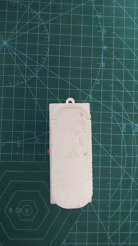
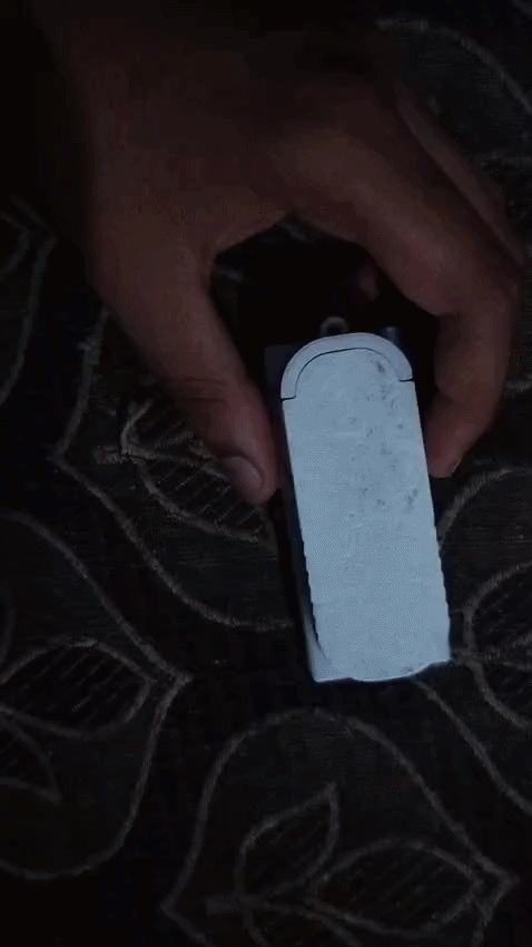

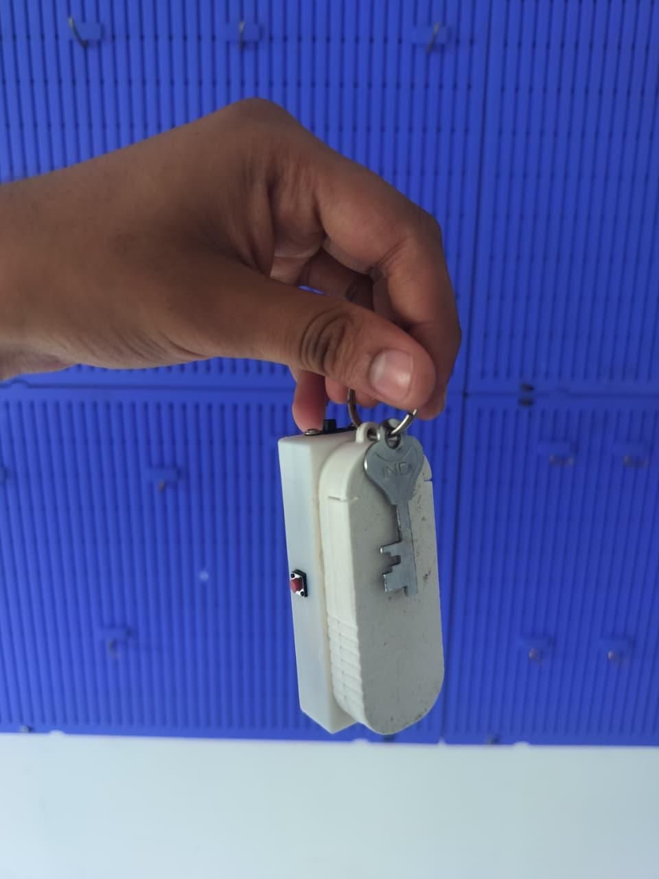
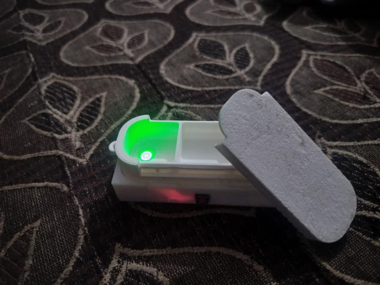
Red means now. Green means done. That's the whole interface.
I've carried PocketPill every day since I built it, and I haven't missed a TB dose since. Not because it's clever — because it fixes the one thing that kept going wrong. My alarms weren't the problem. Carrying the reminder was. Now the alarm lives with the pills, and the pills live on my keys. The whole system moves through the day with me.
Put the alarm where the pills are. Put the pills where you are. That's the entire design.
All the files — STLs, Arduino sketch, Fusion 360 source — are attached at the top. Build one in a weekend. If you do, hit "I Made It!" — I want to see it.
I built this because I needed it. But TB isn't rare, and neither is any condition where a missed dose matters. If this helps one other person stay on their treatment, that's the whole point.