PolyShot Point and Shoot Camera
by Arnov Sharma in Circuits > Cameras
1857 Views, 27 Favorites, 0 Comments
PolyShot Point and Shoot Camera
Greetings, everyone, and welcome back!
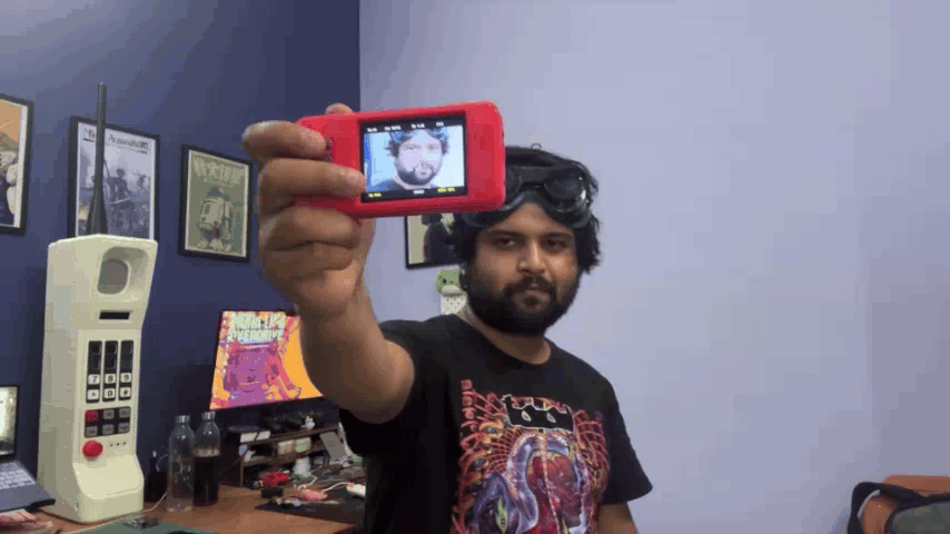
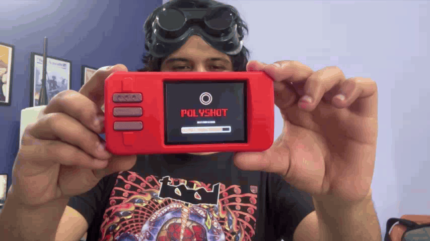
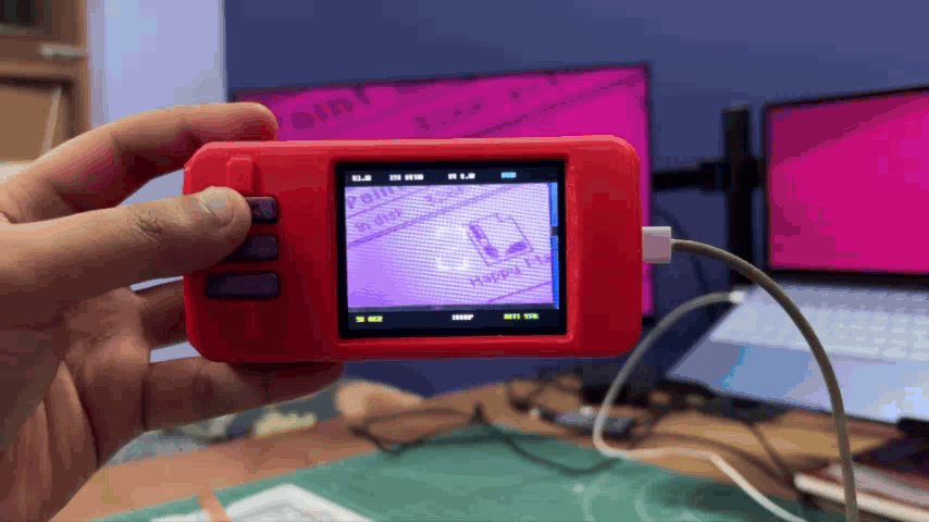
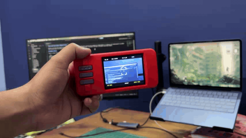
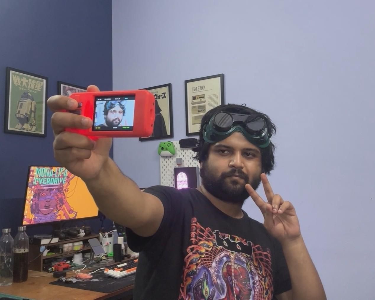
Here's something fun: meet PolyShot, a DIY point-and-shoot camera that I built from scratch.
Lately, point-and-shoot cameras have been making a comeback. My social media feeds have been full of people showing off old Sony Cyber-shot, Canon, and Nikon cameras. Rather than buying one like everyone else, I decided to build my own.
At the heart of this project is the UNIHIKER K10 development board, which is powered by the ESP32-S3 and features a built-in 2-megapixel camera. I designed a custom enclosure for the camera along with a custom button PCB that connects to the UNIHIKER board through its edge connector.
The UNIHIKER also has a microSD card slot, where all captured photos are stored as BMP images. These images can either be viewed directly on the camera or transferred to a computer by simply removing the SD card.
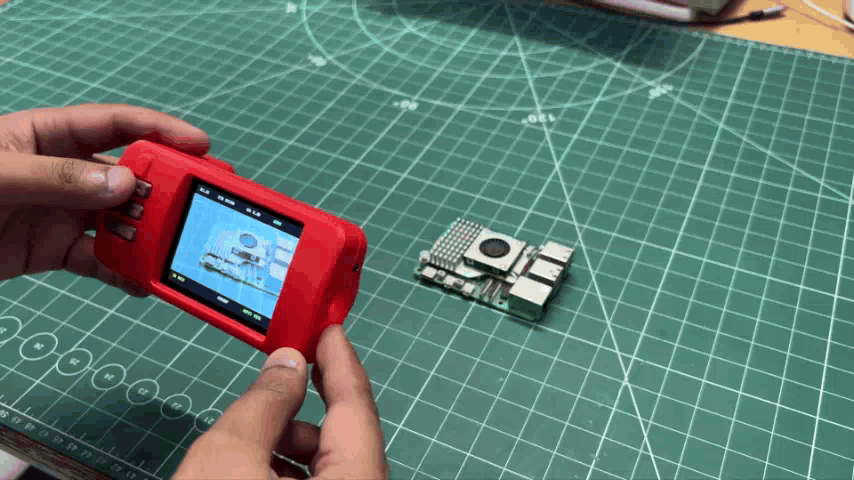
The camera works just like any basic point-and-shoot camera: you point it at your subject, press the shutter button, wait a few seconds, and the image is captured and saved to the SD card.
In this article, I'll walk you through the complete build process, so let's get started!
Supplies
These were the components used in this project.
- Custom Switch PCB (provided by HQ NEXTPCB)
- Unihiker K10 Dev Board
- SD Card
- 3D printed Parts
- M2.5 screws
- M2 self-tapping screws
- Li-ion Cell 3.7V 300mAh 1450 Package
- Push Switch
- JST Battery Connector
THE COMEBACK OF THE POINT AND SHOOT CAMERA
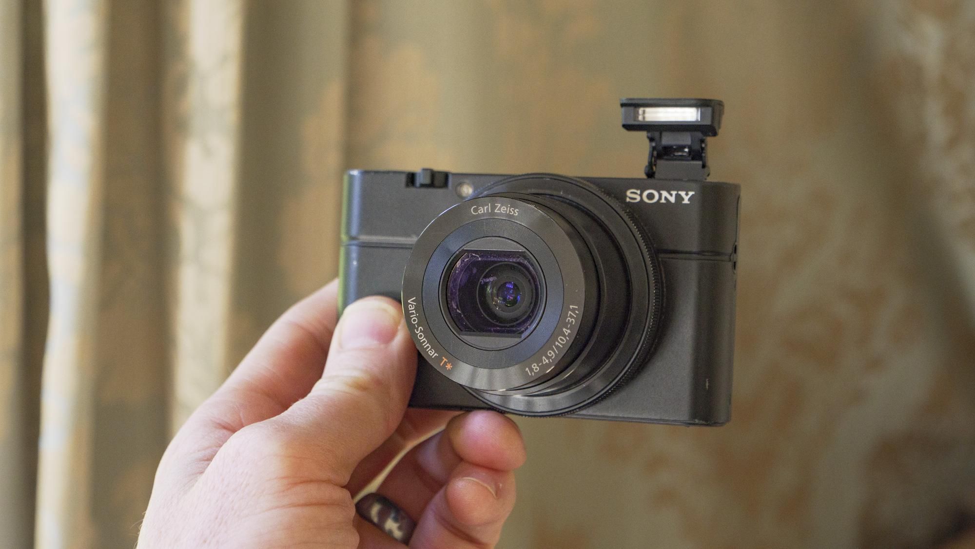

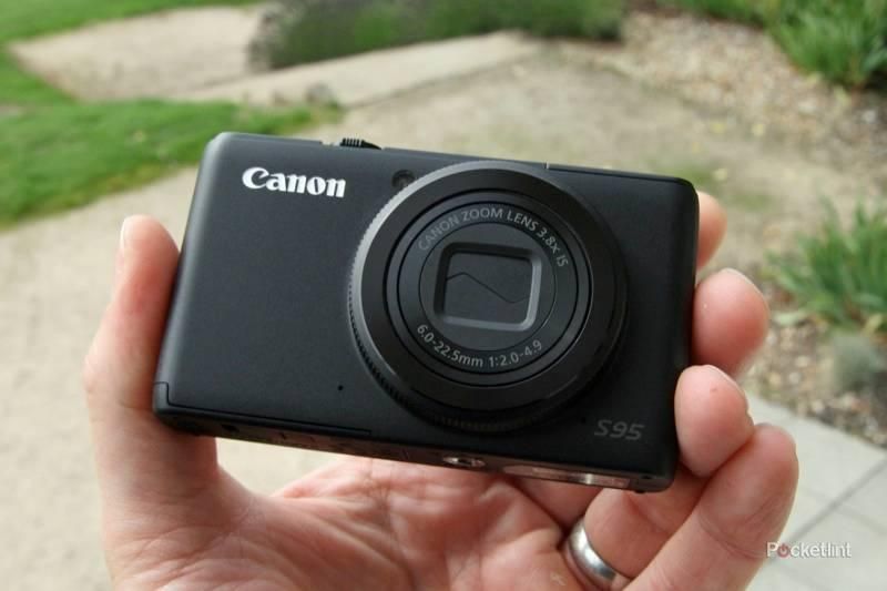
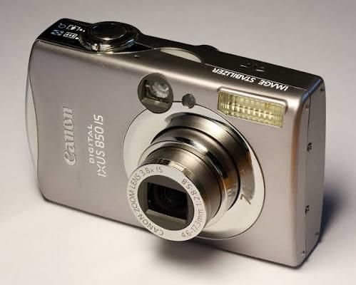
If you've spent any time on Instagram, TikTok, or YouTube recently, you've probably noticed that compact digital cameras are making a huge comeback. Vintage point-and-shoot cameras from brands like Sony, Canon, Nikon, Fujifilm, and Panasonic have become incredibly popular again, especially models from the early 2000s.
Part of the appeal is their unique image quality. Unlike modern smartphones that rely heavily on computational photography, these older cameras produce photos with a distinct look: slightly softer images, natural colors, and a nostalgic digital aesthetic that many people now prefer.
The renewed popularity has also driven up prices. Cameras that were once sitting unused in drawers or thrift stores are now being sold online for surprisingly high prices.
This was one of the reasons why I wanted to build one from scratch.
Originally, I wanted to buy a non-working camera for cheap and retrofit my own electronics inside its body, but that plan failed due to the increased prices and low availability caused by the high demand.
In the end, I had to design and build my own enclosure as well.
HARDWARE- UNIHIKER K10
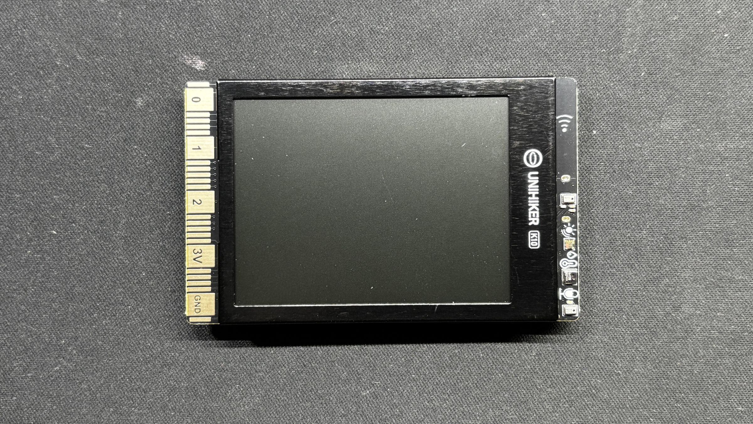
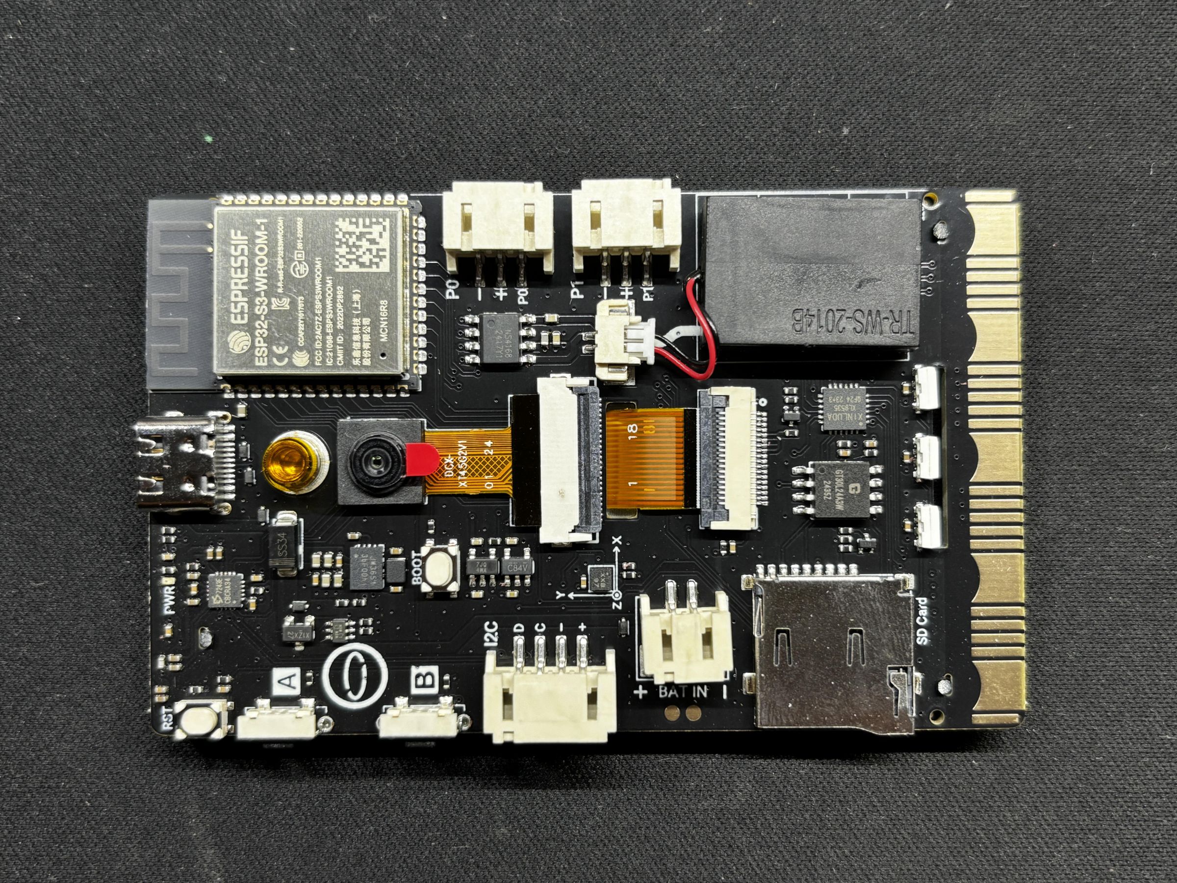
The star of this project is the UNIHIKER K10, which serves as the brain of our camera project.
The UNIHIKER platform is available in two variants: the M10 and the K10.
The M10 is based on a Linux-capable processor, designed for higher-level applications.
The K10, on the other hand, is powered by the ESP32-S3 N16R8 module; this is what we are using.
Key Specifications:
- Module: ESP32-S3 N16R8
- Processor: Xtensa® LX7 dual-core 32-bit CPU
- Clock Speed: Up to 240 MHz
- SRAM: 512 KB
- ROM: 384 KB
- Flash Memory: 16 MB
- PSRAM: 8 MB
- RTC SRAM: 16 KB
With its dual-core architecture and generous Flash and PSRAM, the ESP32-S3 is capable of handling image rendering, SD card file access, and audio playback simultaneously.
Our primary reason for selecting the UNIHIKER K10 for this project was its built-in Camera, a decent 240x320 display, and SD card reader. These two features significantly simplified the overall design and eliminated the need for additional external modules.
All images will be captured and stored directly on the SD card.
Check out more about the Unihiker K10 from its wiki page.
SWITCH BOARD PCB DESIGN
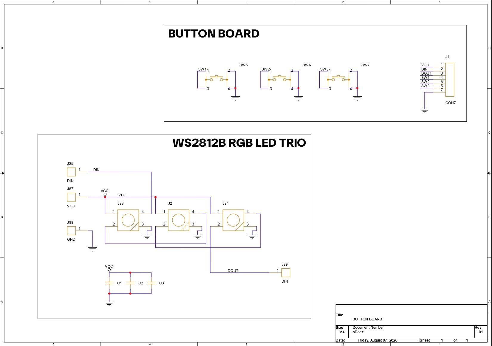
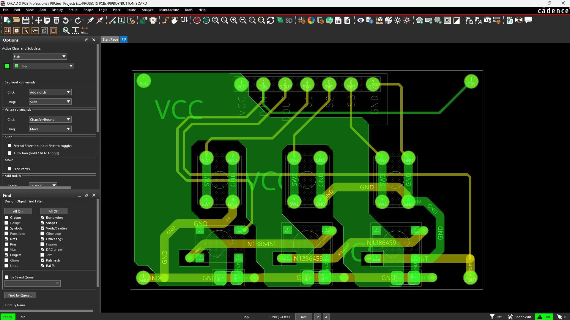
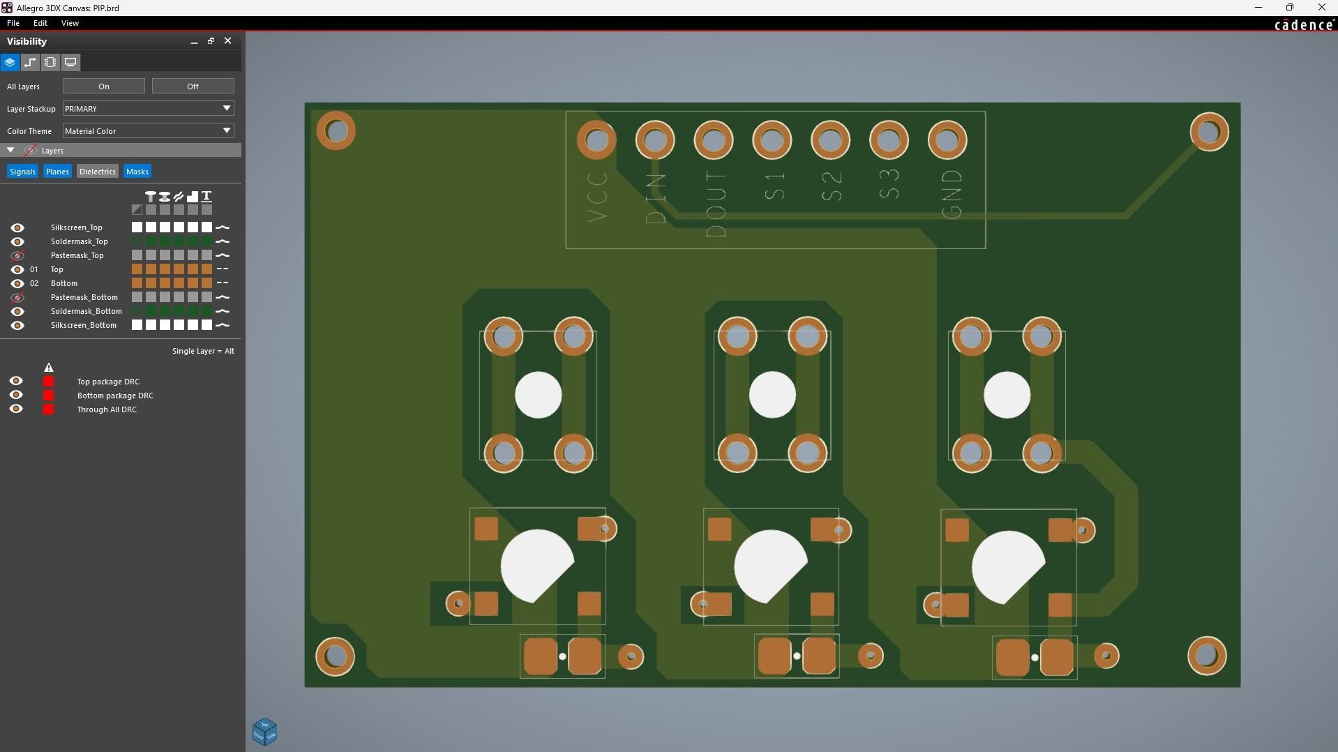
For the PCB design of this project, I needed a simple board with three buttons: one shutter button to capture an image, a second button to open the camera gallery and view the captured photos, and a third button to navigate to the next image in the gallery.
I designed a custom PCB and created the schematic, where all three buttons share a common GND connection. The second terminal of each button is routed to a 3-pin connector (CON3), which interfaces with the UNIHIKER K10.
There are also three WS2812B RGB LEDs added on board. In this project, I didn't use this feature of the board, but this is for a future project in which my plan is to use this same board but with RGB LEDs added.
NextPCB PCB SERVICE
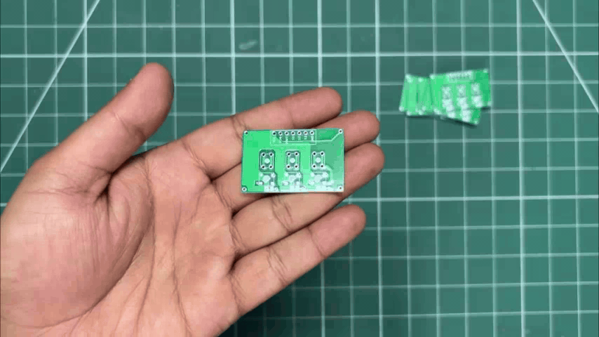
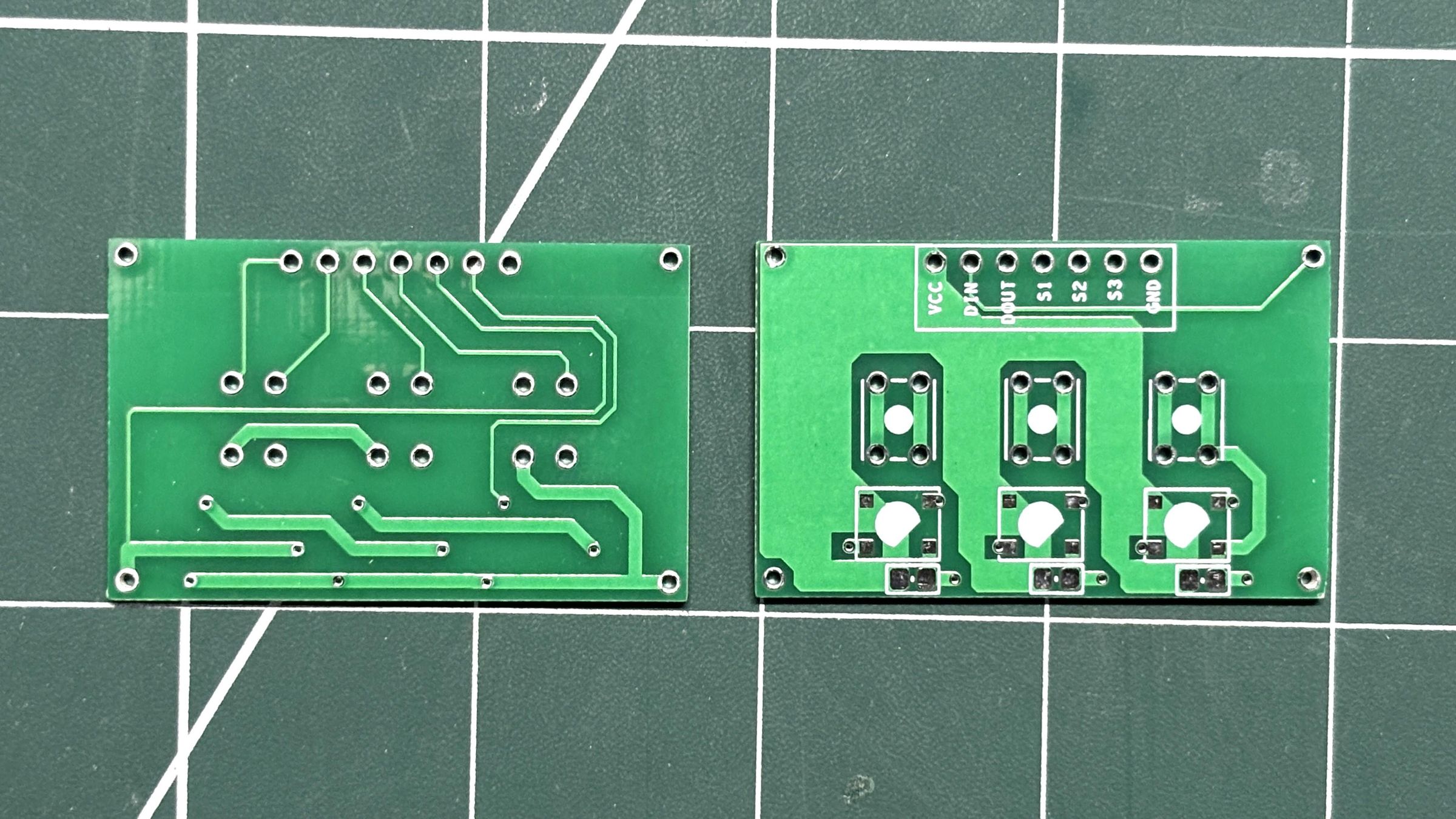
After completing the PCB design, Gerber data for the PCB was sent to HQ NextPCB, and an order was placed for Green Solder mask boards with a white silkscreen.
After placing the order, the PCBs were received within a week, and the PCB quality was pretty great.
In addition, I have to bring in HQDFM to you, which has helped me a lot through many projects. Huaqiu’s in-house engineers developed the free Design for Manufacturing software, HQDFM, revolutionizing how PCB designers visualize and verify their designs.
Take advantage of NextPCB's Accelerator campaign and get 2 free assembled RP2040-based PCBs for your innovative projects.
https://www.nextpcb.com/blog/rp2040-free-pcba-prototypes-nextpcb-accelerator
This offer covers all costs, including logistics, making it easier and more affordable to bring your ideas to life. SMT services can be expensive, but NextPCB is here to help you overcome that hurdle. Simply share your relevant project, and they'll take care of the rest. Don't miss out on this amazing opportunity to advance your tech creations!
HQDFM: Free Online Gerber Viewer and DFM Analysis Tool
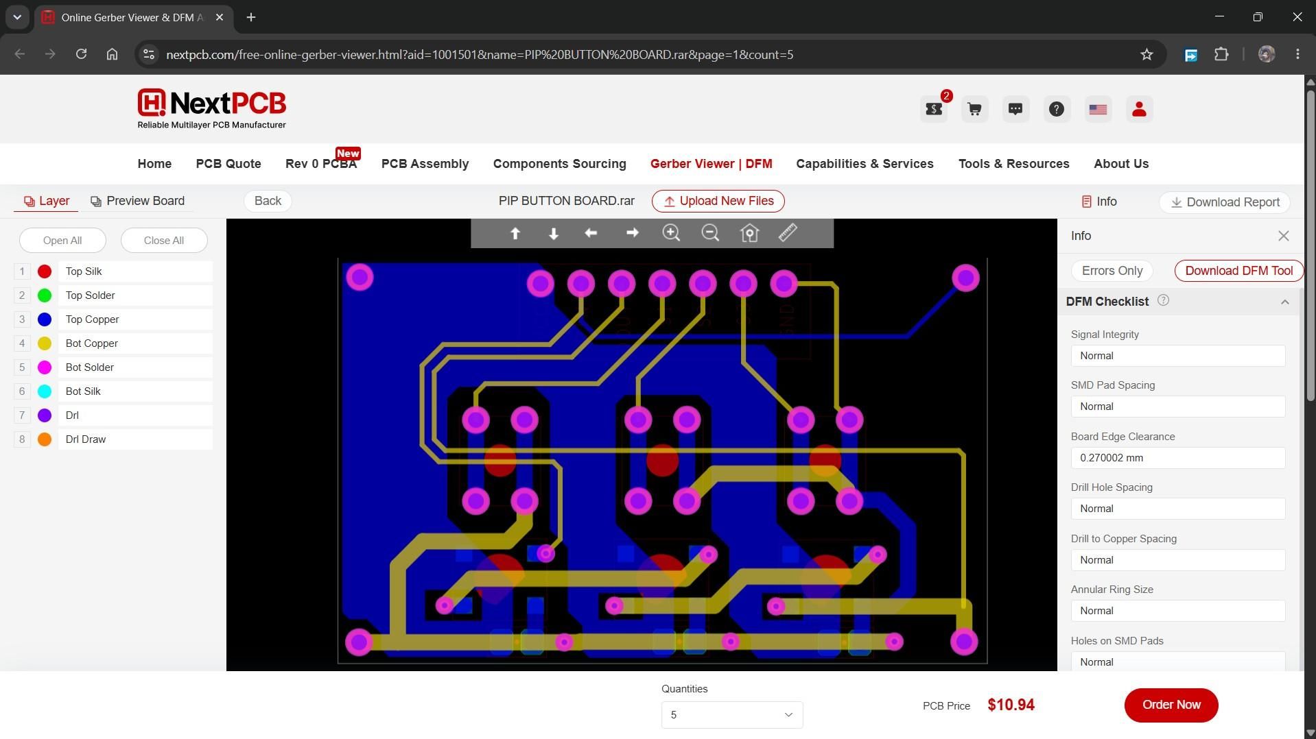
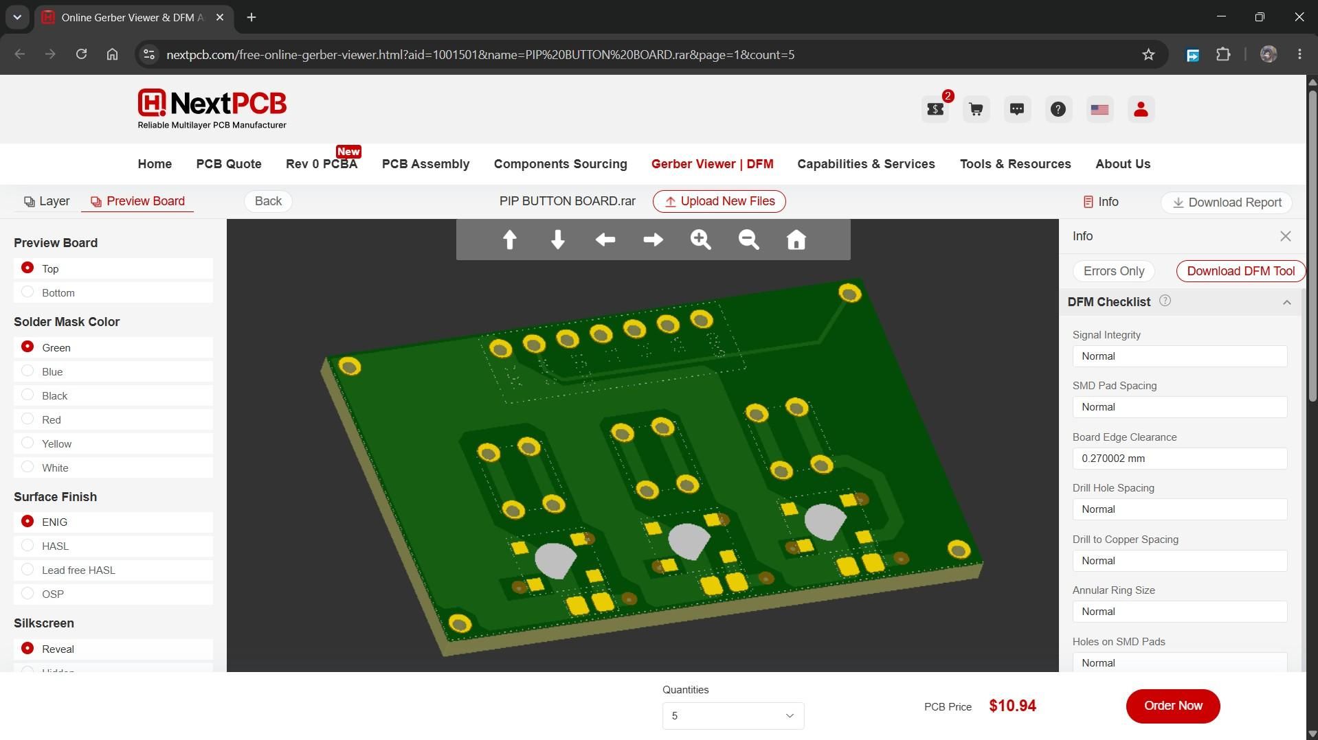
Also, NextPCB has its own Gerber Viewer and DFM analysis software.
Your designs are improved by their HQDFM software (DFM) services. Since I find it annoying to wait for DFM reports from manufacturers, HQDFM is the most efficient way to perform a pre-event self-check.
This is what I see in the online Gerber Viewer. It's decent for a quick look, but not entirely clear. For full functionality—like detailed DFM analysis for PCBA—you’ll need to download the desktop software. The web version only offers a basic DFM report.
With comprehensive Design for Manufacture (DFM) analysis features, HQDFM is a free, sophisticated online PCB Gerber file viewer.
With over 15 years of industry experience, it offers valuable insights into advanced manufacturing processes. If you’re looking for reliable PCB services at a budget-friendly price, HQ NextPCB is definitely worth checking out.
PCB ASSEMBLY PROCESS
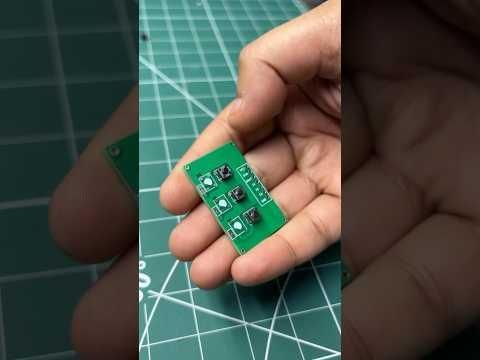
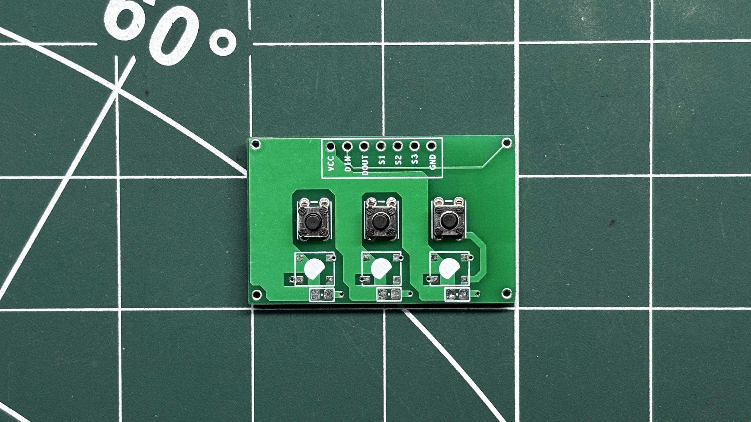
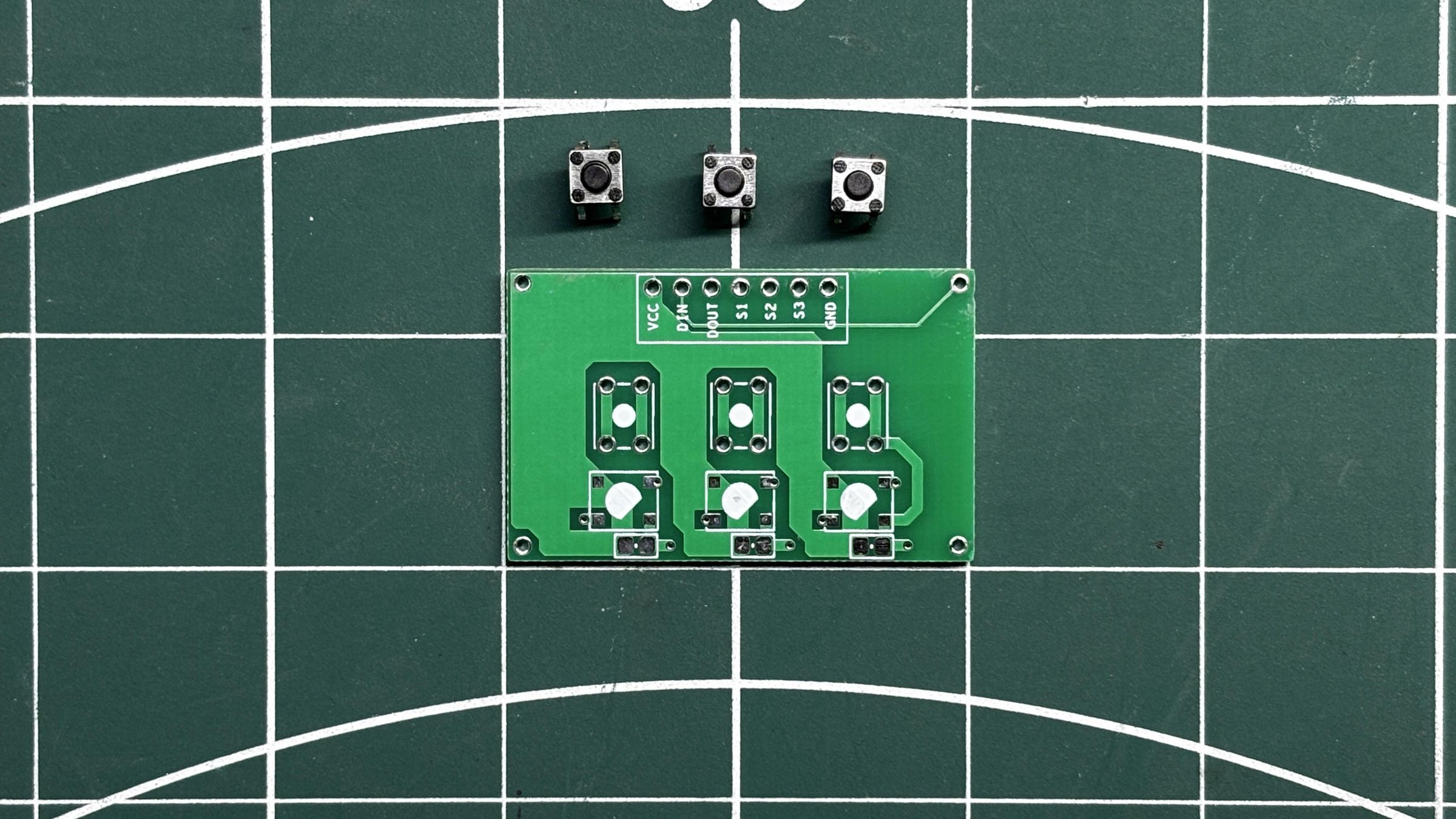
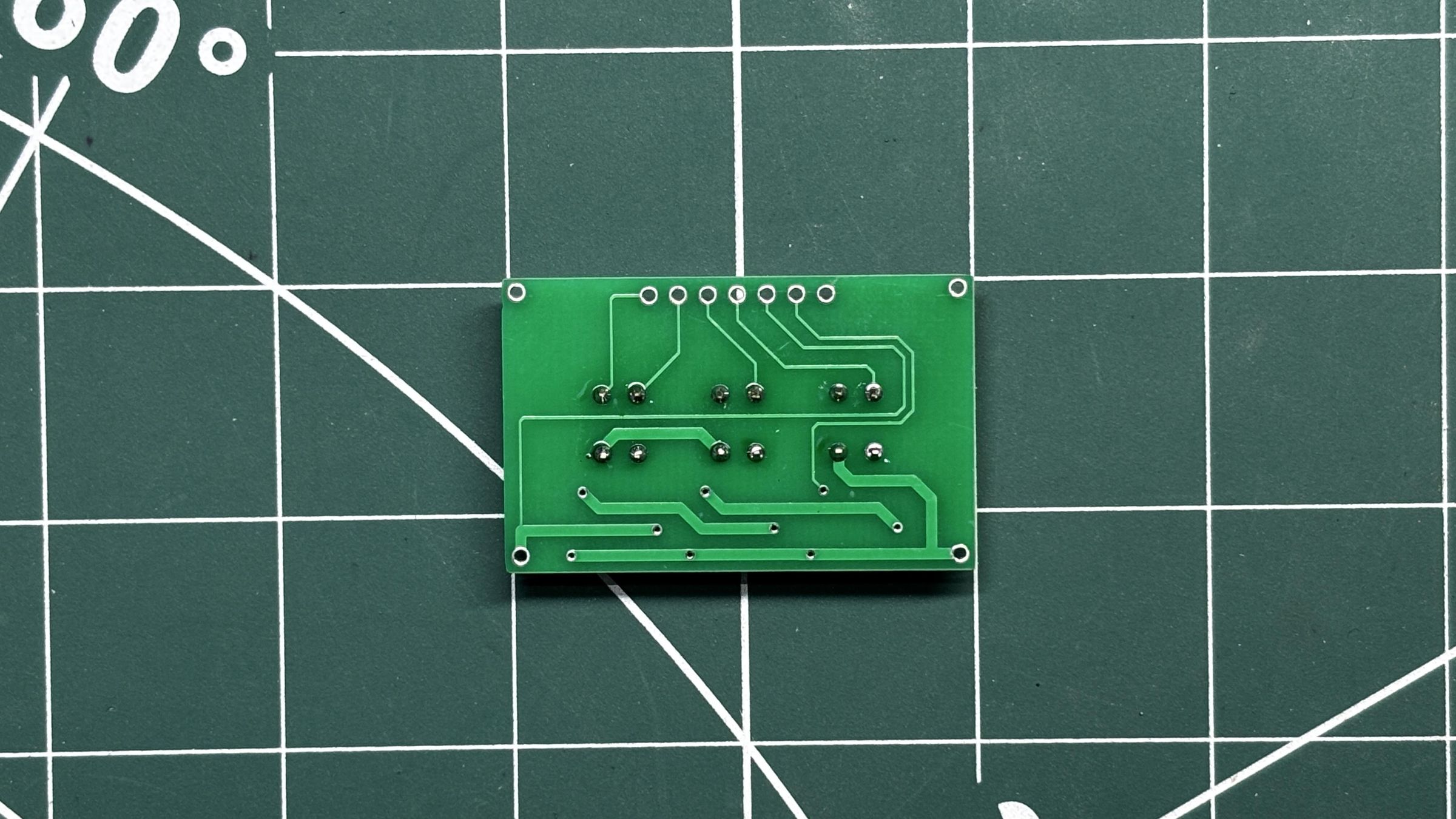
The assembly process for the switch board was also quite simple and straightforward.
- I used three 4×4 mm tactile push buttons, placing each one in its designated position on the PCB.
- The board was then flipped over, and the pads were soldered in place using a soldering iron.
With that, the assembly of the switch board was complete.
CAMERA DESIGN
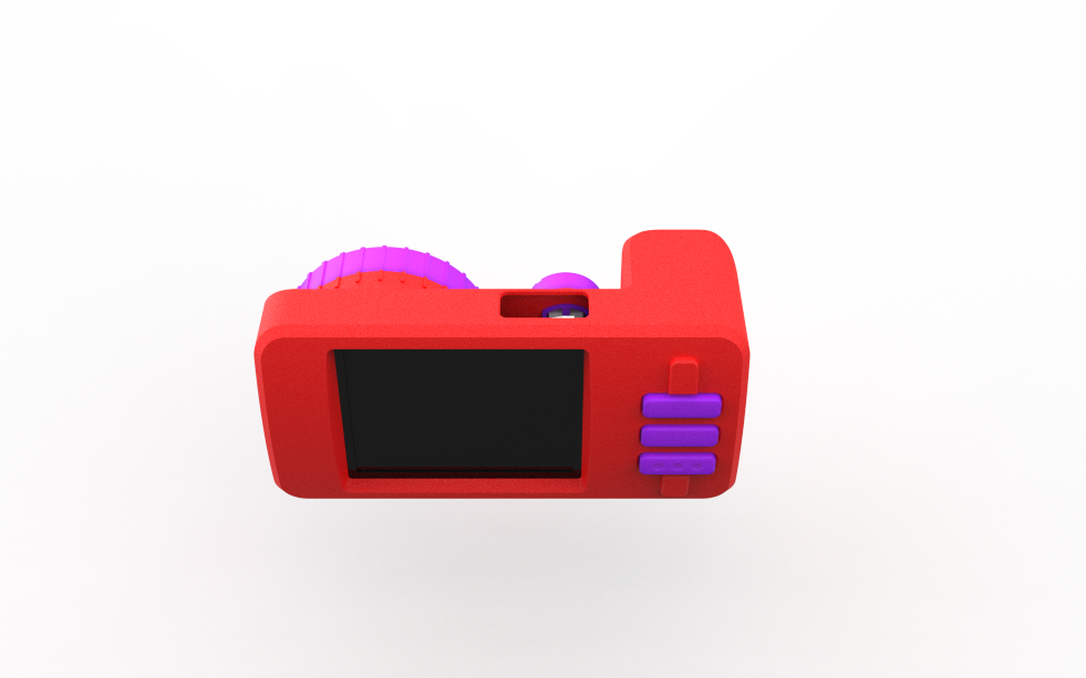
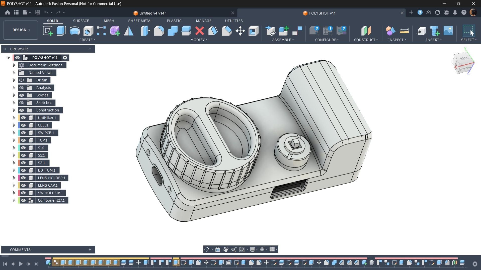
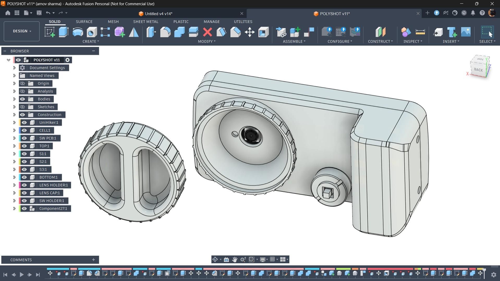
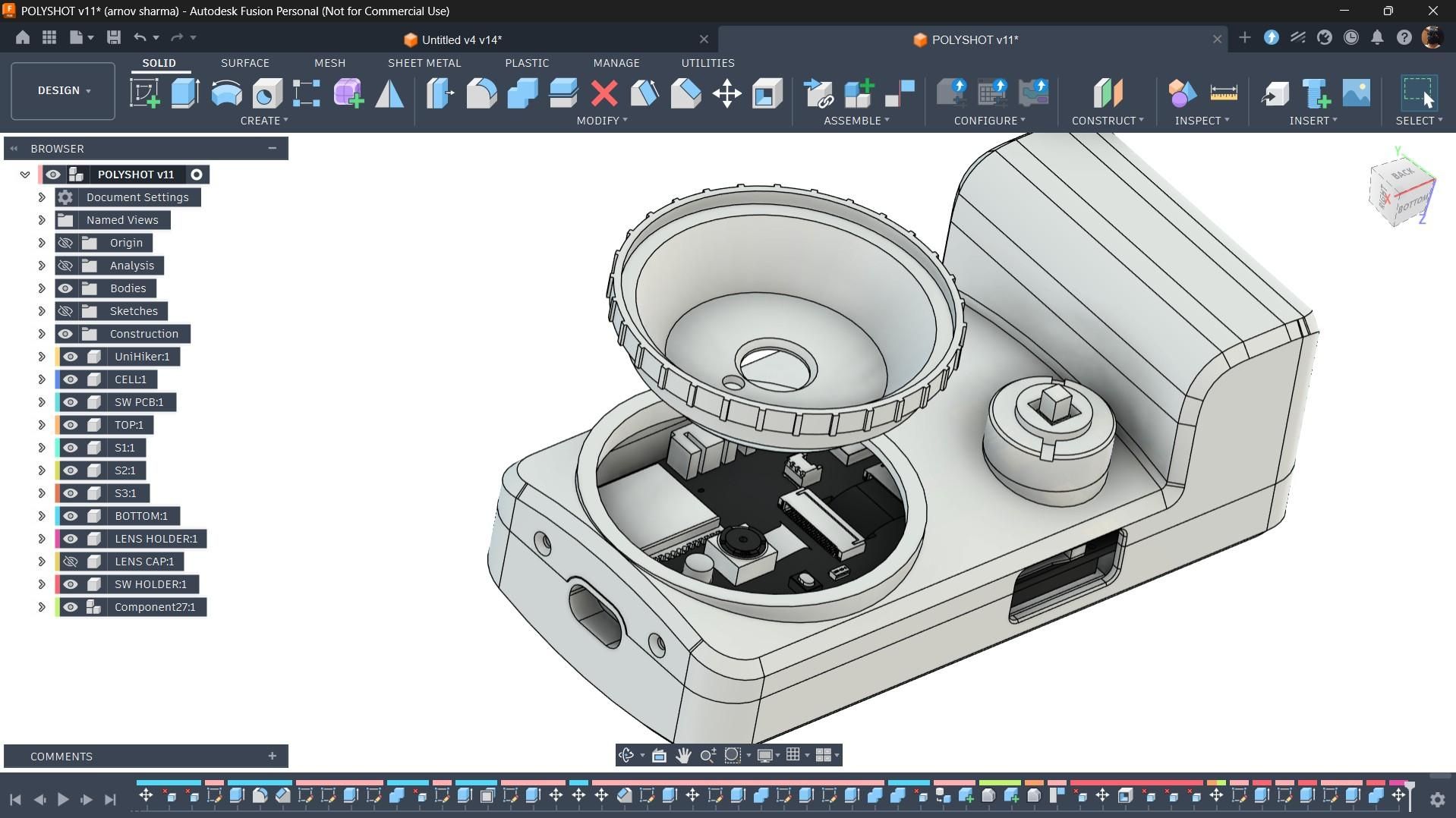
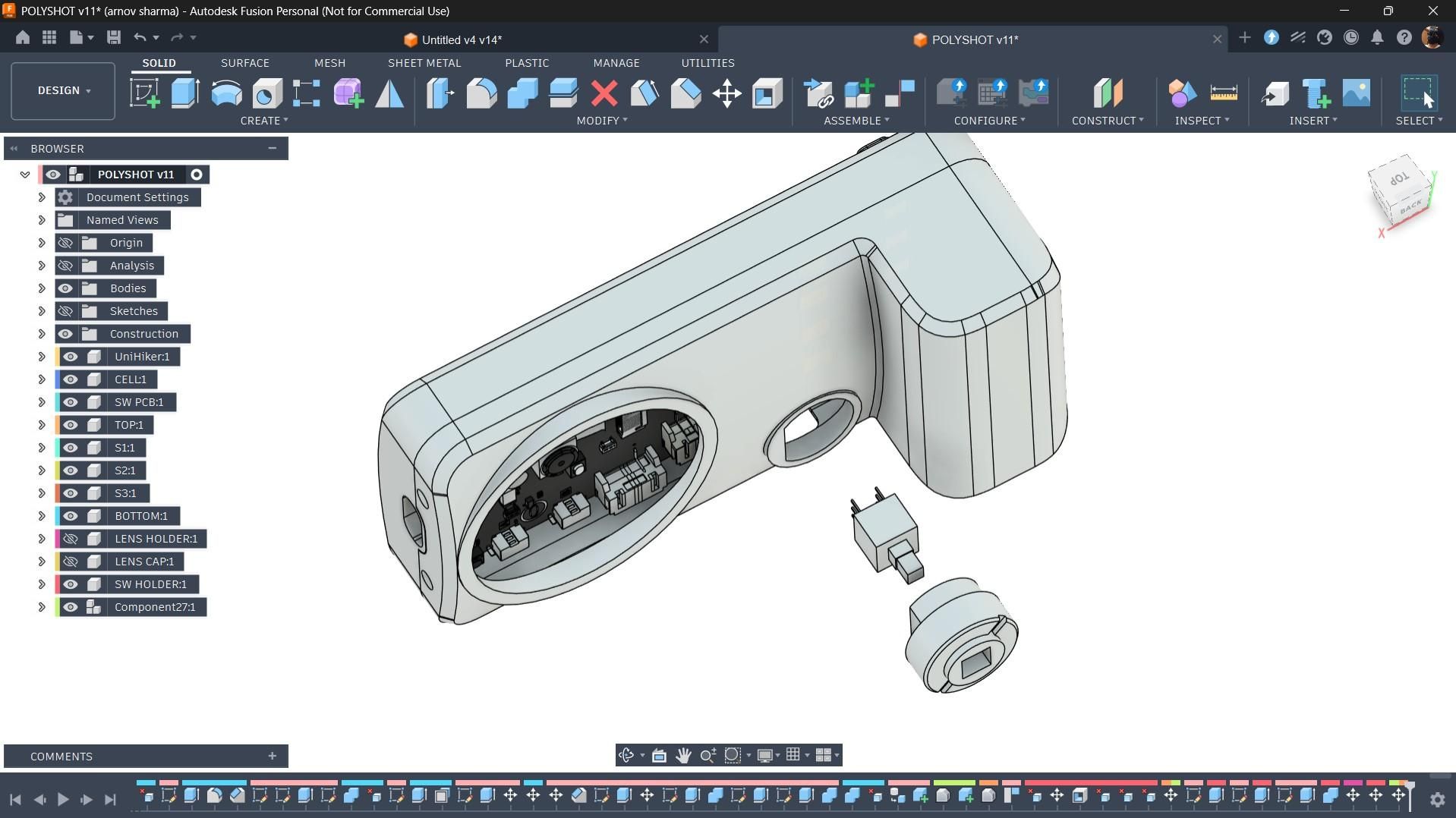
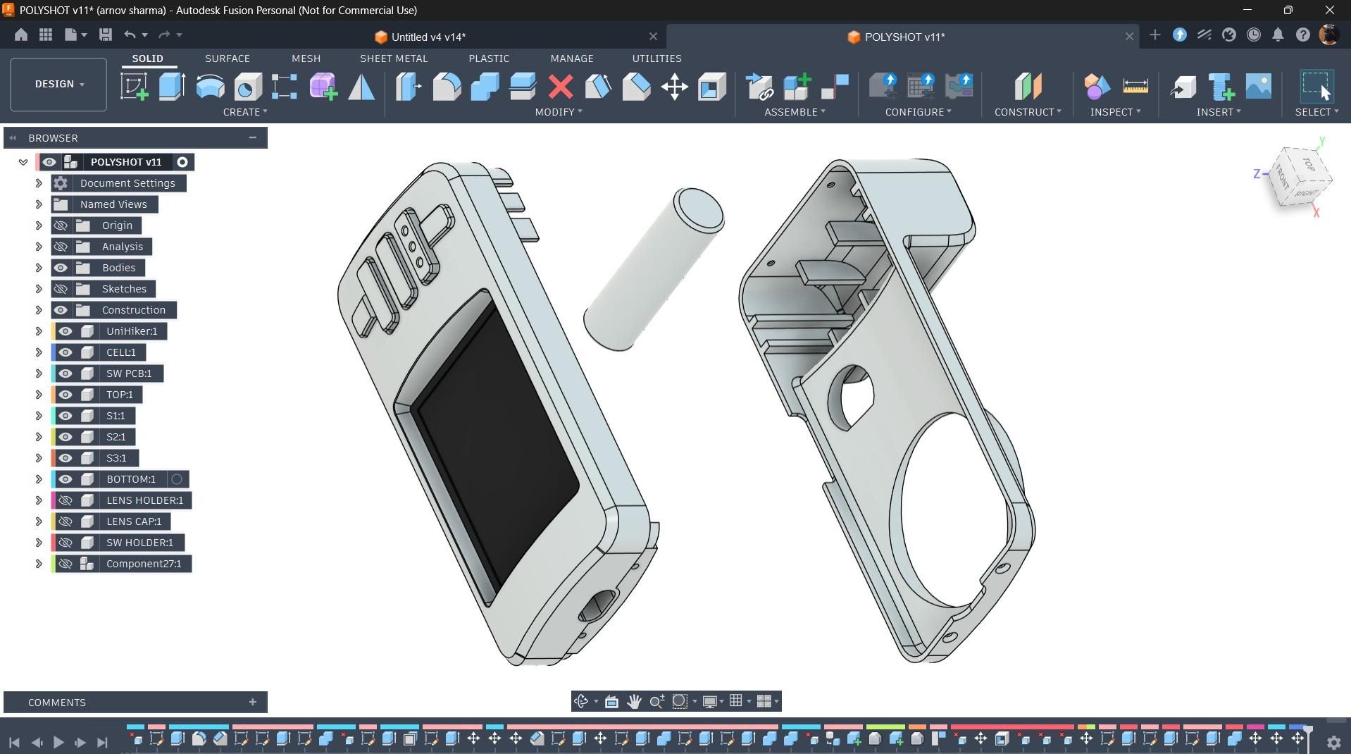
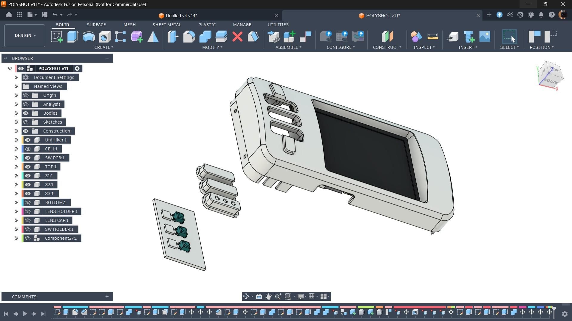
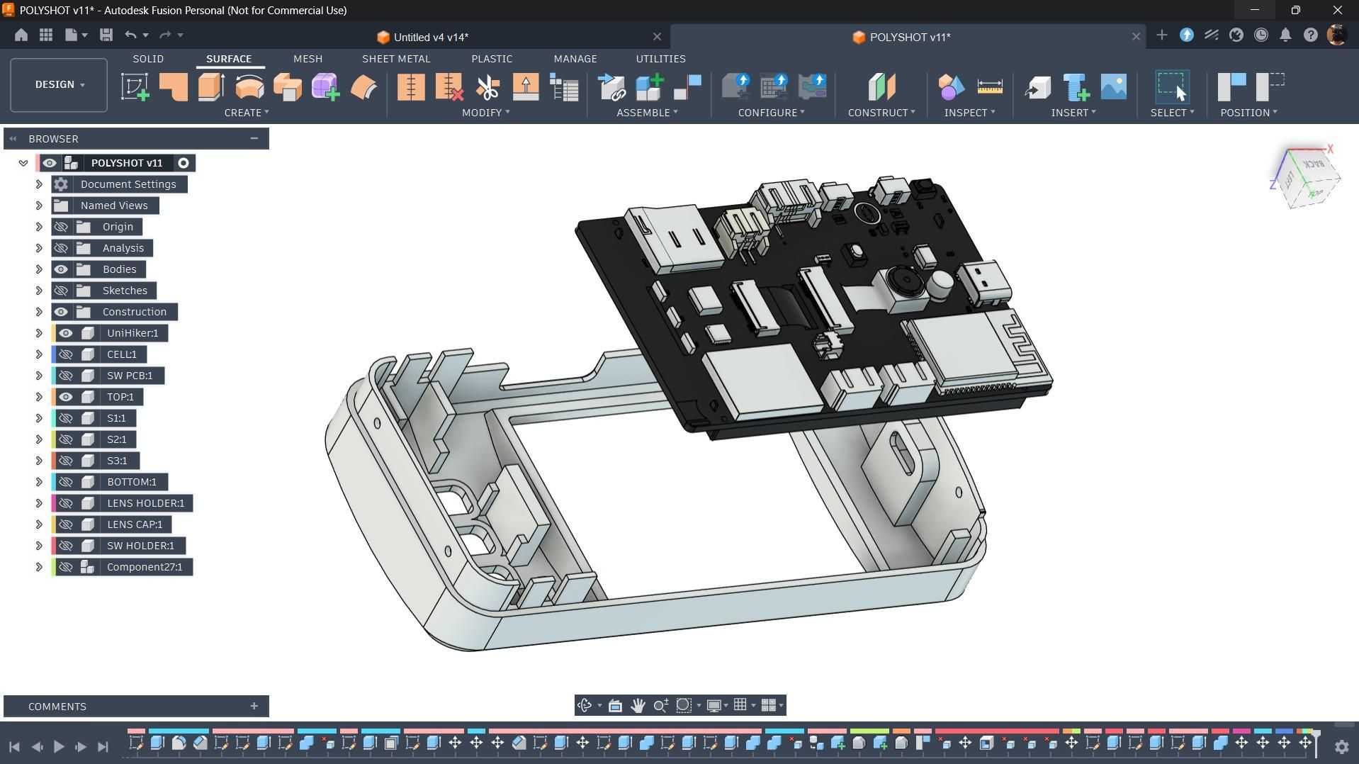
For the design of this project, I wanted to keep things minimal, with less emphasis on aesthetics and more on practicality. I first arranged the UNIHIKER board, battery, and switch PCB in their optimal positions and then designed the enclosure around them.
The battery is positioned in such a way that it also forms a comfortable grip on the left side of the camera, making it easier to hold. Just above the grip is the switch PCB, allowing the shutter button to be comfortably reached with the left thumb. I also included an opening for the microSD card, making it easy to insert or remove the card without disassembling the camera.
The enclosure is divided into two main parts: the front enclosure and the back enclosure.
The back enclosure houses the 14500 Li-ion battery and the main ON/OFF switch and features a large circular opening for the lens holder. The lens holder is a separate part that fits around the UNIHIKER camera module. An M2.5 bolt passes through both the UNIHIKER board and the lens holder, securely holding everything in place. A separate lens cover is then pressure-fitted onto the lens holder to complete the front of the camera.
The front enclosure holds the UNIHIKER board, the switch PCB, and the three switch actuators. The switch PCB is mounted directly behind the actuators, while the UNIHIKER board is secured within the enclosure. Openings are also provided for the USB Type-C port and the microSD card slot, allowing both to remain accessible even after assembly.
3D PRINTED PARTS
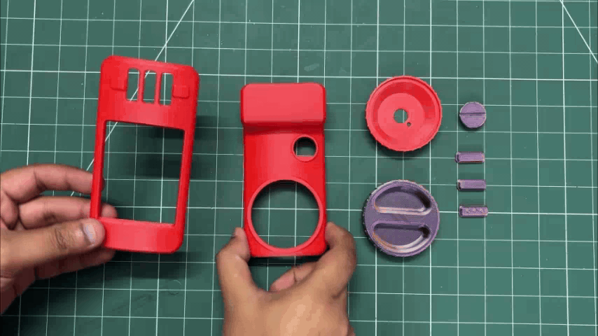
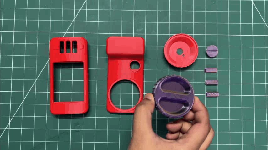
For the 3D printing, the majority of the parts, including both halves of the enclosure and the lens holder, were printed using red Hyper PLA. I printed the enclosure in a vertical orientation to reduce support marks and achieve a smoother surface finish.
The lens cover, switch knobs, and switch holder were all printed using a tri-color PLA, which gives the parts a purple, yellow, and brownish appearance. This color combination complements the red enclosure quite well.
POWER SOURCE
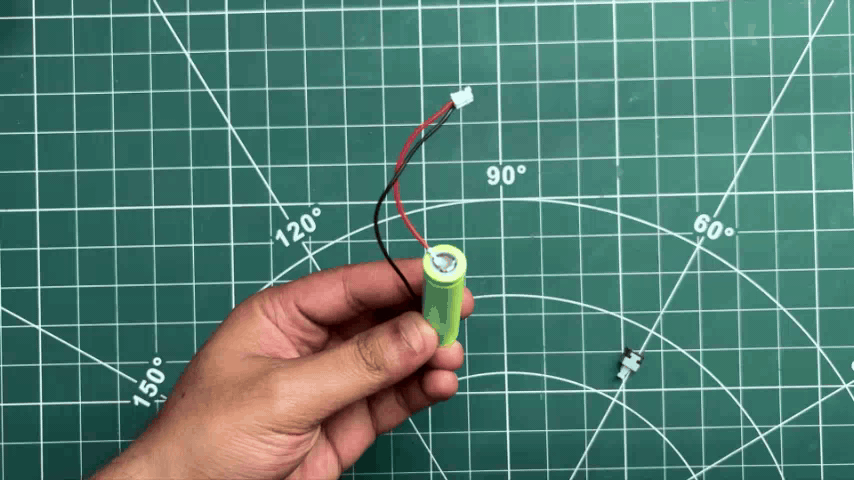
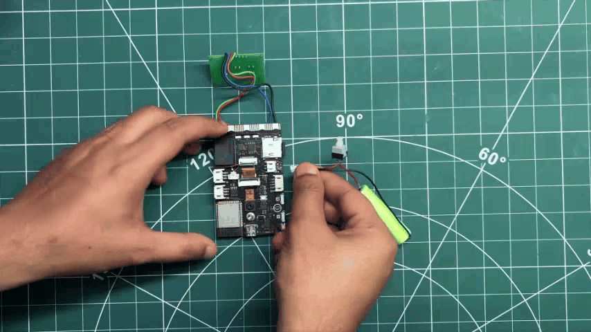
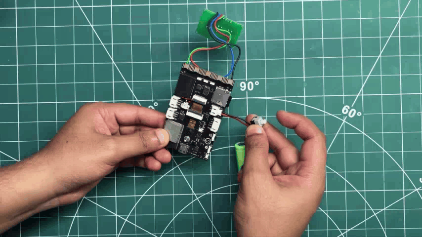
For the power source of this project, the ideal option would have been a LiPo cell. However, I had a compact 14500-size Li-ion cell available, so I decided to use it for this build.
Here, I'm using a 3.7 V, 300 mAh Li-ion cell. To connect it, I spot-welded a battery JST wire harness to the positive and negative terminals.
The harness comes with nickel strips already attached to the wires, making it easy to spot-weld them directly to the cell terminals.
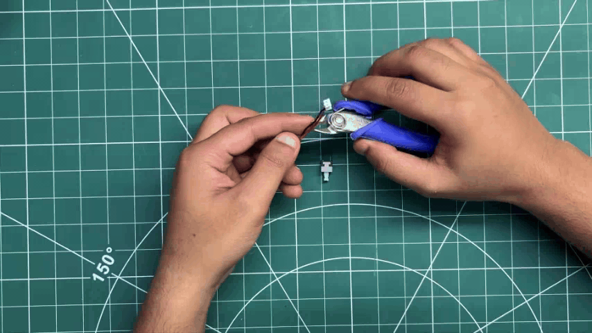
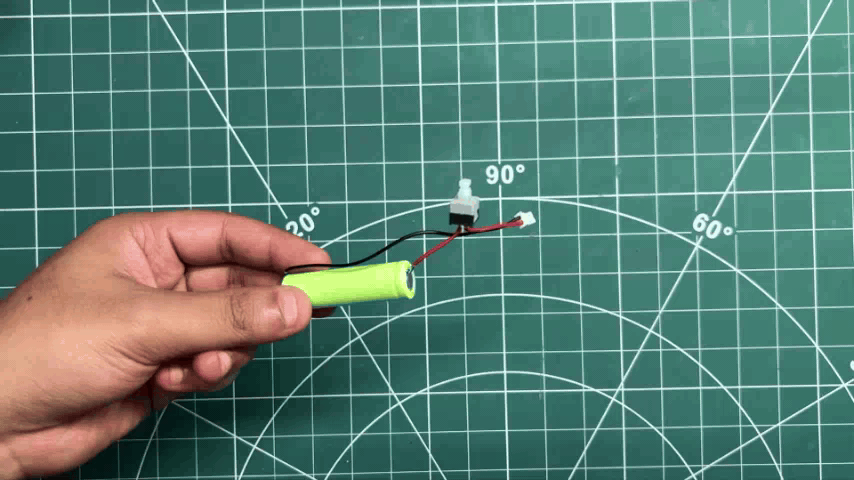
I cut the positive wire in the middle and added a small ON/OFF push switch in between. This acts as the main power switch for the battery, since the UNIHIKER board itself doesn't have a dedicated power switch. Without this, the board would remain powered on as long as the battery was connected.
UNIHIKER & SWITCH BOARD ASSEMBLY
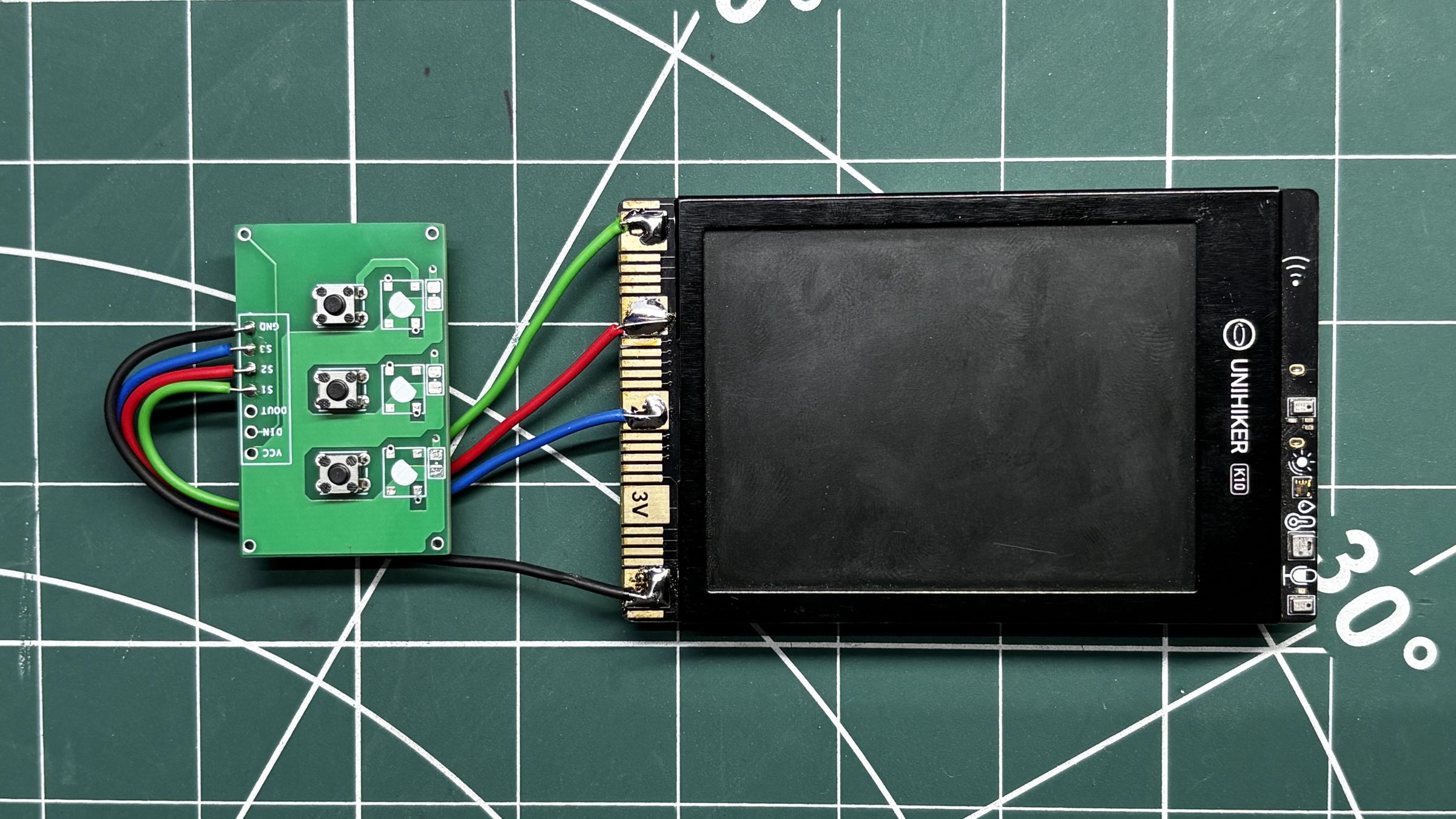
We can now connect the UNIHIKER edge connector to our switch board. All three switches share a common GND terminal, which is connected to the GND pin on the UNIHIKER edge connector.
Next, the three switch outputs are connected to the GPIO pins on the UNIHIKER. Switch 1 is connected to P0 (labeled 0), Switch 2 is connected to P1 (labeled 1), and Switch 3 is connected to P2 (labeled 2).
For all four connections, I used single-core silver-plated copper wire, which made the wiring neat and easy to route inside the enclosure.
CODE
This is the main code for our camera, and it's a simple one.
Library Initialization
The project begins by including the UNIHIKER K10 library and creating a board object. A few global variables are then declared to keep track of the screen orientation, image numbering, gallery state, and button debounce timing.
These variables are used throughout the program to keep track of the current operating mode and prevent accidental multiple button presses.
Custom Font
Instead of relying on built-in fonts, I included a custom 5×7 bitmap font.
Each character is stored as a bitmap, allowing the firmware to draw text pixel by pixel. This also makes it possible to rotate the text to match the display orientation used by the camera.
Graphic Engine
To simplify drawing on the display, I created a few helper functions that are reused throughout the project.
The first helper function draws filled rectangles by repeatedly drawing horizontal lines.
The second helper function renders rotated text using the custom bitmap font.
These helper functions are used throughout the project to create every screen and UI element.
Splash Screen
When the camera powers on, it first displays a custom boot animation.
This function draws the PolyShot logo, loading text, and an animated progress bar before switching to the live camera feed.
Camera User Interface
Once the camera starts, a custom HUD is drawn over the live camera preview.
This interface includes:
- Camera settings
- Image counter
- SD card indicator
- Battery status
- Focus reticle
The UI gives the project the appearance of a real compact digital camera.
Gallery Interface
Captured images are viewed using a separate gallery mode.
Whenever Gallery Mode is opened, the selected BMP image is loaded directly from the microSD card and displayed on the screen, along with a few navigation labels.
Image Capture
The shutter button calls the image capture routine.
This function performs four tasks:
- Flashes the RGB LED to simulate a camera flash.
- Captures the current camera frame.
- Saves the image as a BMP file on the microSD card.
- Updates the image counter shown on the display.
The complete image capture process takes approximately three seconds.
Camera & Gallery Mode Switching
The camera has two operating modes: Camera Mode and Gallery Mode.
Pressing the Gallery button switches between these two modes. When entering Gallery Mode, the latest captured image is automatically displayed. Returning to Camera Mode restores the live camera preview and redraws the camera HUD.
Image Navigation
Inside Gallery Mode, the third button is used to browse through previously captured images.
Each button press loads the next BMP image from the microSD card. Once the last image is reached, the gallery loops back to the first image.
Setup Function
The setup() function initializes all of the hardware before the camera begins operating.
During initialization, the firmware:
- Starts the UNIHIKER K10
- Initializes the display
- Starts the camera
- Creates the graphics canvas
- Initializes the microSD card
- Configures the RGB LEDs
- Configures the three GPIO buttons
- Displays the splash screen
- Draws the camera interface
After this, the live camera preview becomes active.
Main Loop
The loop() function continuously monitors the three buttons connected to the UNIHIKER.
Whenever a valid button press is detected, the firmware calls the corresponding function:
- P0 → takePictureAction() → Capture image
- P1 → toggleModeAction() → Switch between Camera and Gallery modes
- P2 → scrollImageAction() → Display the next image
A 200 ms software debounce ensures that each press is registered only once, preventing accidental multiple triggers.
FRONT ENCLOSURE ASSEMBLY
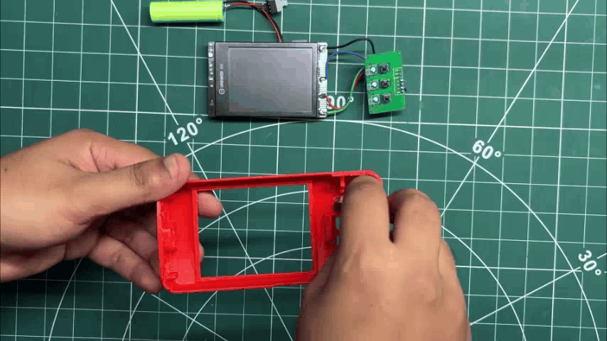
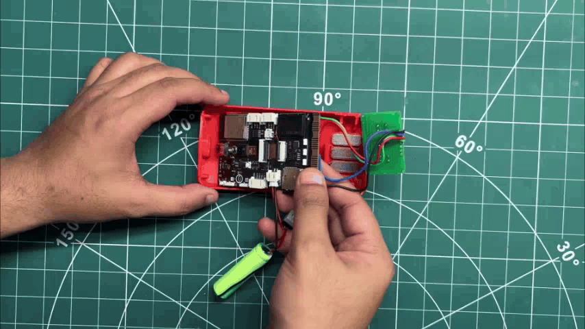
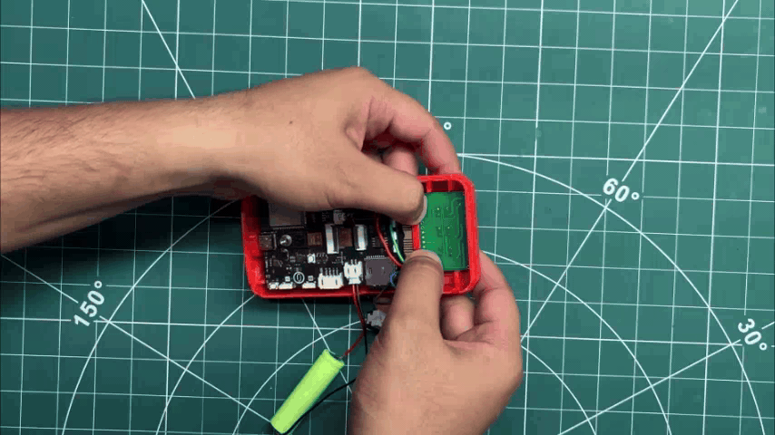
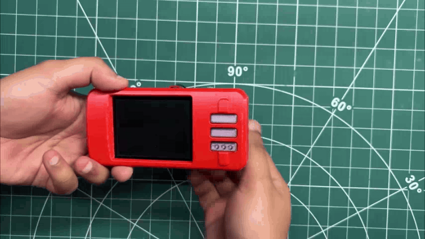
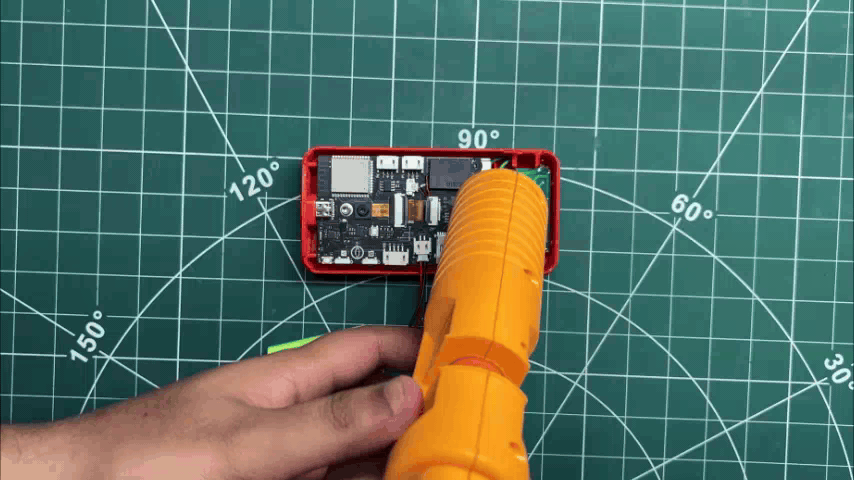
- We begin the front enclosure assembly by placing the three switch actuators into their positions.
- Next, the UNIHIKER board is placed into the enclosure, where it is pressure-fitted into place. This is followed by positioning the switch PCB directly above the switch actuators.
- To ensure that everything remains securely in place during use, I applied a small amount of hot glue to both the UNIHIKER board and the switch PCB. This prevents any movement while still keeping the assembly process simple.
BACK ENCLOSURE ASSEMBLY
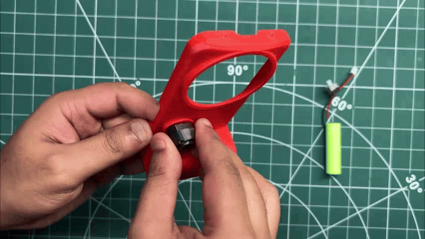
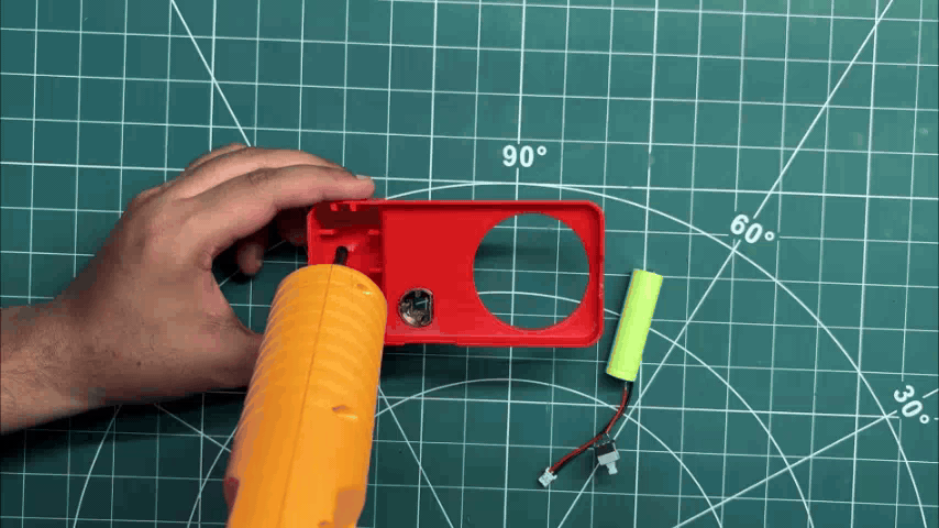
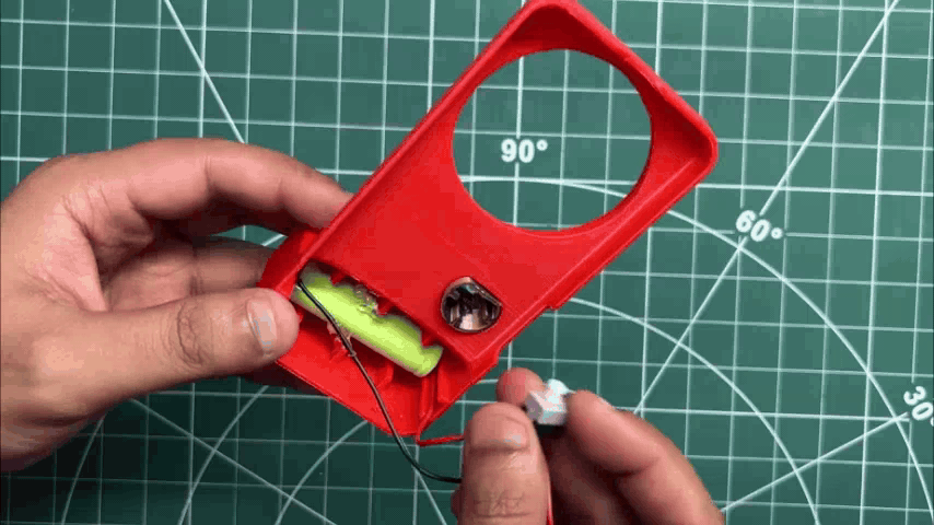
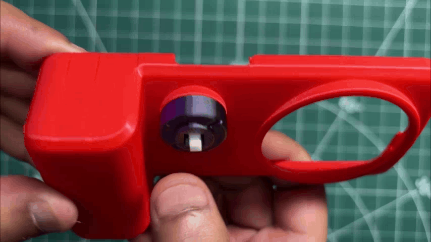
- On the back enclosure, we first place the switch holder into its position from the outside of the enclosure.
- Next, we apply hot glue to the battery compartment and place the lithium cell in its designated position, where it is secured using the hot glue.
- The ON/OFF switch is then inserted into the switch holder from the inside. The switch is pressure-fitted into place, while its actuator remains accessible from the outside of the camera.
FINAL ASSEMBLY
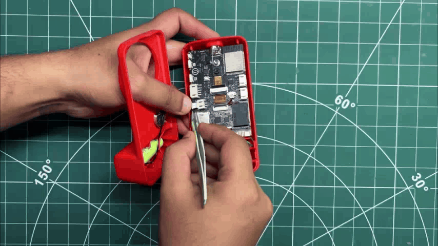

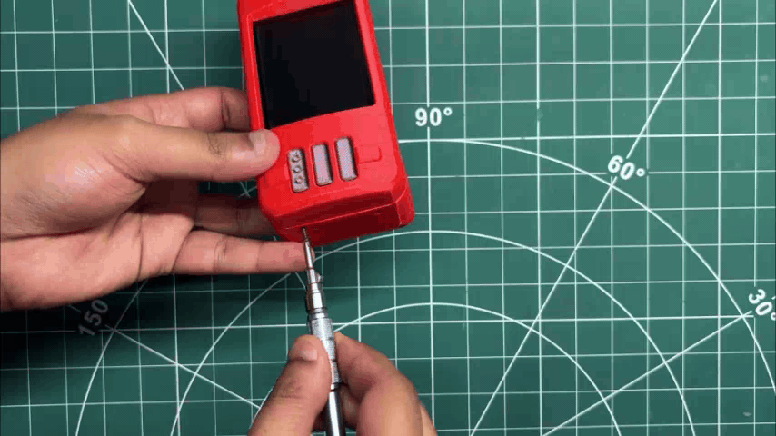
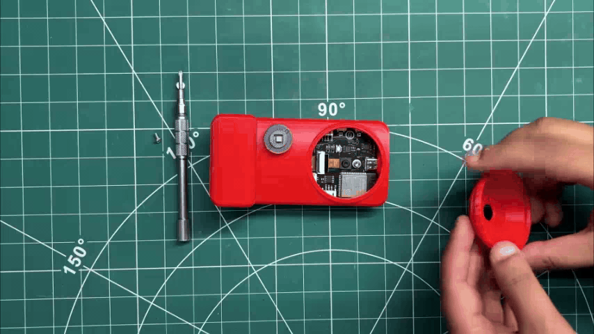
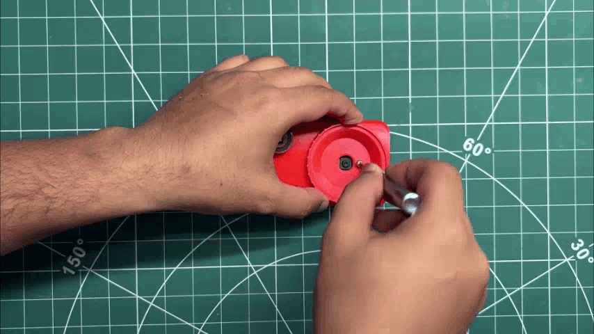
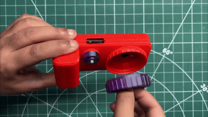
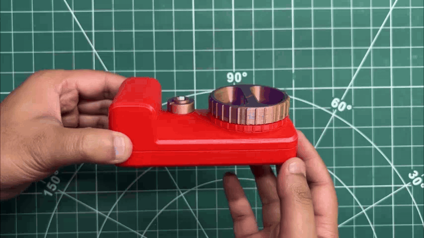
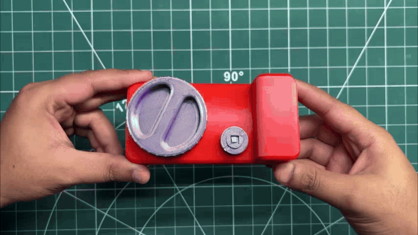
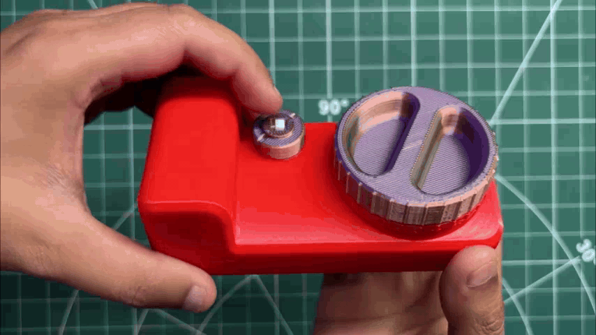
- Now comes the final assembly process, which begins by reconnecting the battery's JST connector to the battery connector on the UNIHIKER board.
- Next, we bring the front and back enclosures together. They fit together tightly, and two M2 self-tapping screws are installed on both the left and right sides to securely fasten the two halves together.
- From the front, I place the lens holder in position, align its mounting hole with the mounting standoff on the UNIHIKER board, and use an M2.5 bolt to secure the lens holder to the UNIHIKER board.
With that, the assembly process of the camera is complete.
RESULT
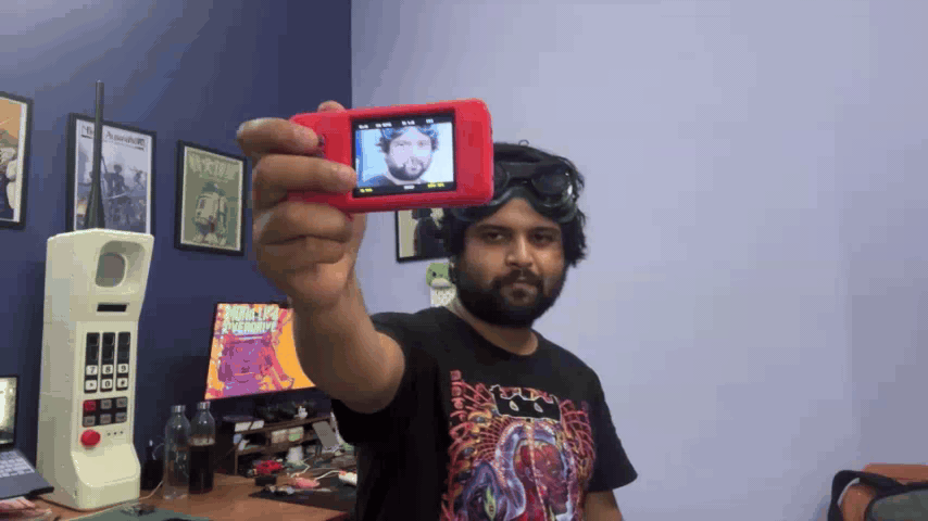
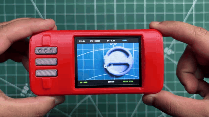
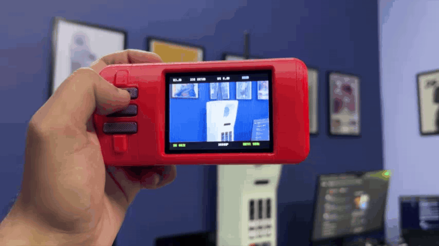
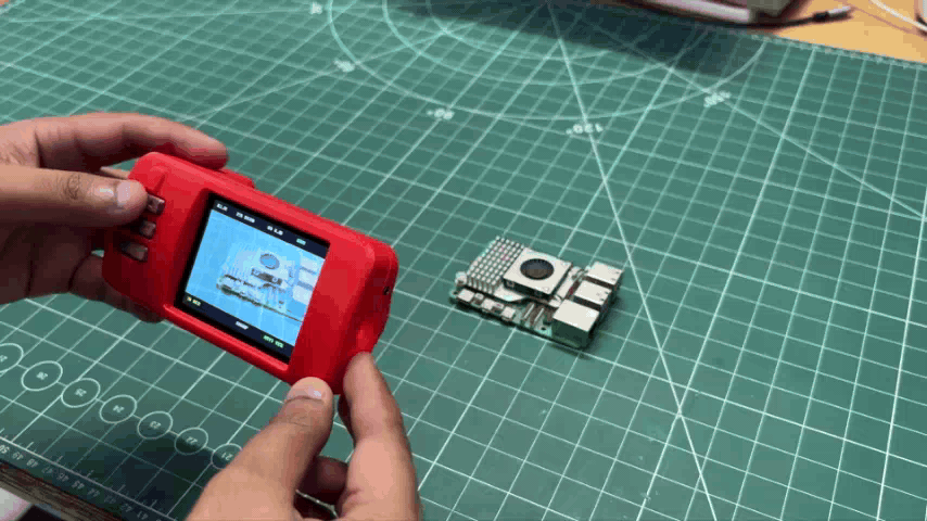
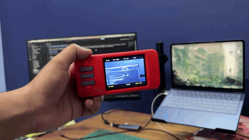
Now here's the result of this build: PolyShot, a DIY open-source point-and-shoot camera.
Pressing the main ON/OFF button powers on the camera, displaying a custom splash screen with the PolyShot logo and a loading bar. Once the boot process is complete, the camera enters the main camera HUD. Simply remove the lens cap, and the camera is ready to capture photos.
Pressing the shutter button captures an image. The camera takes about three seconds to process and save the photo. You can then press the second button to open the gallery and use the third button to browse through the captured images. If you remove the microSD card and open it on a computer, you'll find all of the photos stored in BMP format.
The operation of the camera is intentionally simple. Point it at your subject, press the shutter button, and wait a few seconds, and the image is captured and saved to the microSD card, just like a classic point-and-shoot camera.
CONCLUSION
Overall, I'd consider this project a success. The goal was to build a fully functional DIY point-and-shoot camera, and that's exactly what PolyShot became. It can capture photos, store them on a microSD card, and even preview the captured images directly on the device.
That said, there are still plenty of improvements to make. The biggest one is image quality. My original idea was actually to build a very low-resolution "dumb camera" or pixel camera with a unique retro aesthetic. Along the way, the project evolved into a more traditional digital camera instead. While I'm happy with the result, I think there's still room to experiment with different sensors and image-processing techniques in future versions.
Battery life is another area that could be improved. The current prototype runs for around three hours on a single charge, which is perfectly usable for a prototype but could definitely be better in the next iteration.
For PolyShot V2, I'd also like to move away from the UNIHIKER K10 entirely. Instead of building around a development board, I'd design everything from scratch using an ESP32-S3 module, a dedicated camera sensor, display, power-management circuitry, and all of the supporting electronics integrated onto a single custom PCB. The goal would be to create a much smaller, cleaner, and more production-like camera while keeping the project completely open source.
This project was inspired by the resurgence of compact digital cameras and the idea of creating something unique rather than simply buying one. It has been a fun project to design, build, and document, and I'm really happy with how it turned out.
For now, PolyShot is officially complete. Thanks for following along, and if you decide to build one yourself, I'd love to see your version!
Peace.