Portable Modular Power System With Swappable Battery, Light, DC & Inverter Modules
by HumanixTechLab in Circuits > Tools
32 Views, 0 Favorites, 0 Comments
Portable Modular Power System With Swappable Battery, Light, DC & Inverter Modules
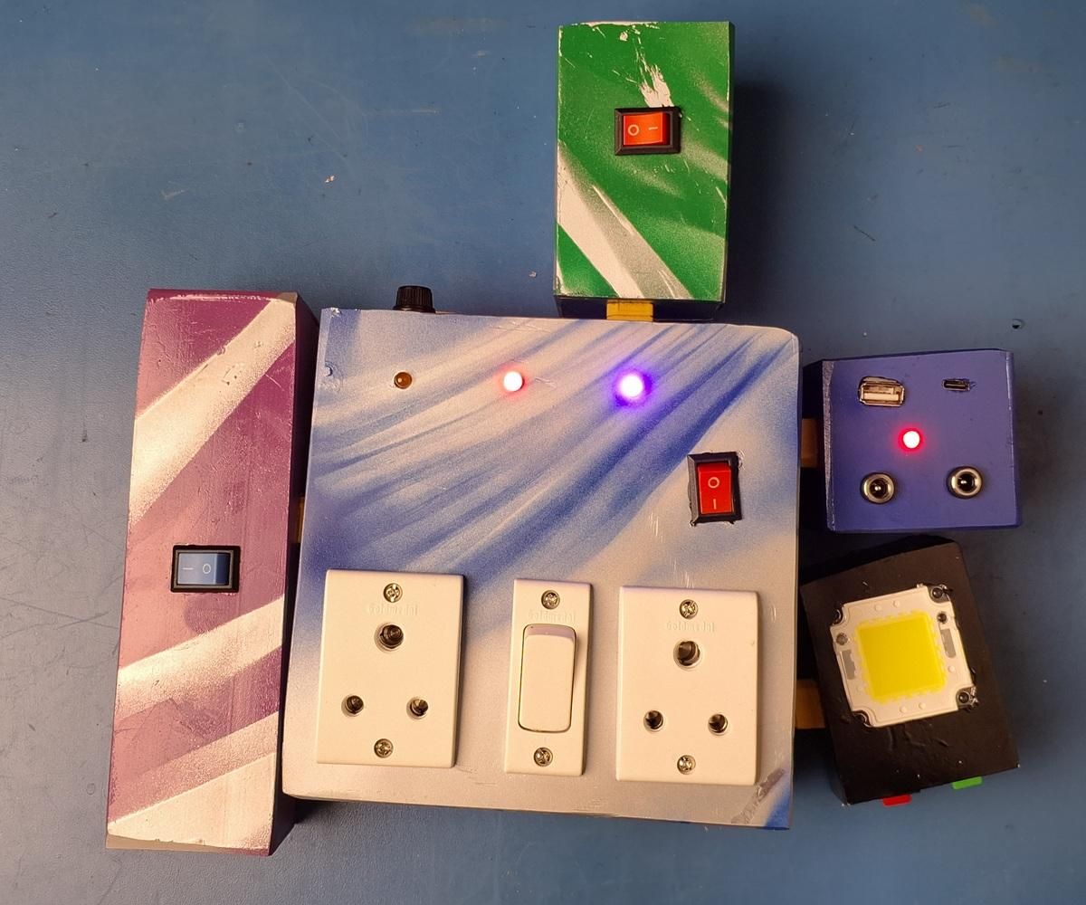
A fixed inverter only does one thing: convert battery DC into AC, and it stays wherever it is installed. This project turns that idea inside out. It is a power system built from separate modules — battery, DC output, lighting, and AC inverter — that connect and disconnect independently through XT60 connectors, so only the modules actually needed for a task get carried into the field.
This project started from a simple frustration during agriculture and remote work: a normal inverter cannot move with you. If you need light while walking a field at night, or DC/USB charging for a phone during a day trip, a fixed inverter is no help at all — you either carry a completely separate device or go without. Commercial all-in-one power stations solve part of this, but they bundle every function into one sealed unit, so you carry the full weight even when you only need the light.
After completing this build, you will have a power system that can be reconfigured on the spot: a light module plus one battery pack for night walking, a battery pack plus the DC module for a day of phone/USB charging, or the full assembly connected to the inverter hub for AC-powered tools — all charged from a 60W solar panel with no dependency on grid power.
What you'll learn building this:
- How to build safe 21700 lithium battery packs in different series/parallel configurations
- How to use a buck converter as a simplified lithium charge controller (and where that approach's limits are)
- How to design a standardized connector interface (XT60) across multiple independent modules
- How to size and fuse a small solar-charged power system
Engineering philosophy for this build: modular, serviceable, and no more complex than it needs to be. Every module should work fully on its own once connected to a battery — nothing should require the entire system to be assembled just to use one part of it.
Now let's gather the required components and start building.
Supplies
A fixed inverter only does one thing: convert battery DC into AC, and it stays wherever it is installed. This project turns that idea inside out. It is a power system built from separate modules — battery, DC output, lighting, and AC inverter — that connect and disconnect independently through XT60 connectors, so only the modules actually needed for a task get carried into the field.
This project started from a simple frustration during agriculture and remote work: a normal inverter cannot move with you. If you need light while walking a field at night, or DC/USB charging for a phone during a day trip, a fixed inverter is no help at all — you either carry a completely separate device or go without. Commercial all-in-one power stations solve part of this, but they bundle every function into one sealed unit, so you carry the full weight even when you only need the light.
After completing this build, you will have a power system that can be reconfigured on the spot: a light module plus one battery pack for night walking, a battery pack plus the DC module for a day of phone/USB charging, or the full assembly connected to the inverter hub for AC-powered tools — all charged from a 60W solar panel with no dependency on grid power.
What you'll learn building this:
- How to build safe 21700 lithium battery packs in different series/parallel configurations
- How to use a buck converter as a simplified lithium charge controller (and where that approach's limits are)
- How to design a standardized connector interface (XT60) across multiple independent modules
- How to size and fuse a small solar-charged power system
Engineering philosophy for this build: modular, serviceable, and no more complex than it needs to be. Every module should work fully on its own once connected to a battery — nothing should require the entire system to be assembled just to use one part of it.
Now let's gather the required components and start building.
SUPPLIES
Electronics
- 150W inverter board/circuit ×1 — Price: Approximate, not yet available Purpose: Converts battery DC to AC output.
- 300W buck converter module ×1 — Price: Approximate, not yet available Purpose: Steps down solar panel voltage and regulates battery charge voltage (used here instead of a dedicated lithium charge-controller IC).
- 21700 lithium-ion cells ×9 — Price: Approximate, not yet available Purpose: Cell stock for both battery packs (3 cells for the 3S1P small pack, 6 cells for the 3S2P large pack).
- Step-down (buck) module for 5V COB light ×1 — Price: Approximate, not yet available Purpose: Converts 12V to 5V for the low-voltage COB light in the light module.
- 12V/20W COB light ×1 — Price: Approximate, not yet available Purpose: Higher-power lighting element in the light module.
- 5V COB light ×1 — Price: Approximate, not yet available Purpose: Lower-power lighting element in the light module, for close work.
- Type-C 65W fast charging circuit ×1 — Price: Approximate, not yet available Purpose: USB-C output on the DC module.
- 12V DC output jacks ×2 — Price: Approximate, not yet available Purpose: DC accessory outputs on the DC module.
- 60W solar panel ×1 — Price: Approximate, not yet available Purpose: Off-grid charging source for the entire system.
- Inline safety fuse ×1 — Price: Approximate, not yet available Purpose: Overcurrent protection for the inverter hub.
- Protection diode ×1 — Price: Approximate, not yet available Purpose: Protects the charge path; its 0.7V forward drop is accounted for in the charge voltage setting.
Hardware / Connectors
- XT60 connector pairs ×5 (minimum) — Price: Approximate, not yet available Purpose: Standardized connect/disconnect interface between all modules and the inverter hub (solar input, large battery, small battery, DC module, light module).
- Toggle switches ×3 — Price: Approximate, not yet available Purpose: Independent on/off control for the DC module, and each COB light in the light module.
Wiring
- Silicone-insulated battery wire (appropriate gauge for 150W/12V loads) — Price: Approximate, not yet available Purpose: Interconnects between cells, modules, and connectors.
Mechanical
- Enclosure material for each module — Information not yet available (material not yet decided) Purpose: Physical housing for battery packs, DC module, light module, and inverter hub.
Consumables
- Solder, flux, heat-shrink tubing — Price: Approximate, not yet available Purpose: Electrical joints and insulation.
Optional Parts
- Battery holders/spacers for 21700 cells — Price: Approximate, not yet available Purpose: Mechanical support and short-circuit prevention for the cell packs.
Tools
- Soldering iron
- Wire cutter/stripper
- Multimeter
- Hot glue gun (or equivalent mounting adhesive)
- Helping hands / third-hand tool
- Heat gun (for heat-shrink)
- Screwdriver set
Optional Tools
- Bench power supply (useful for testing modules before connecting real battery packs)
- Spot welder (if assembling battery packs with nickel strip instead of solder)
Understand the Module Layout
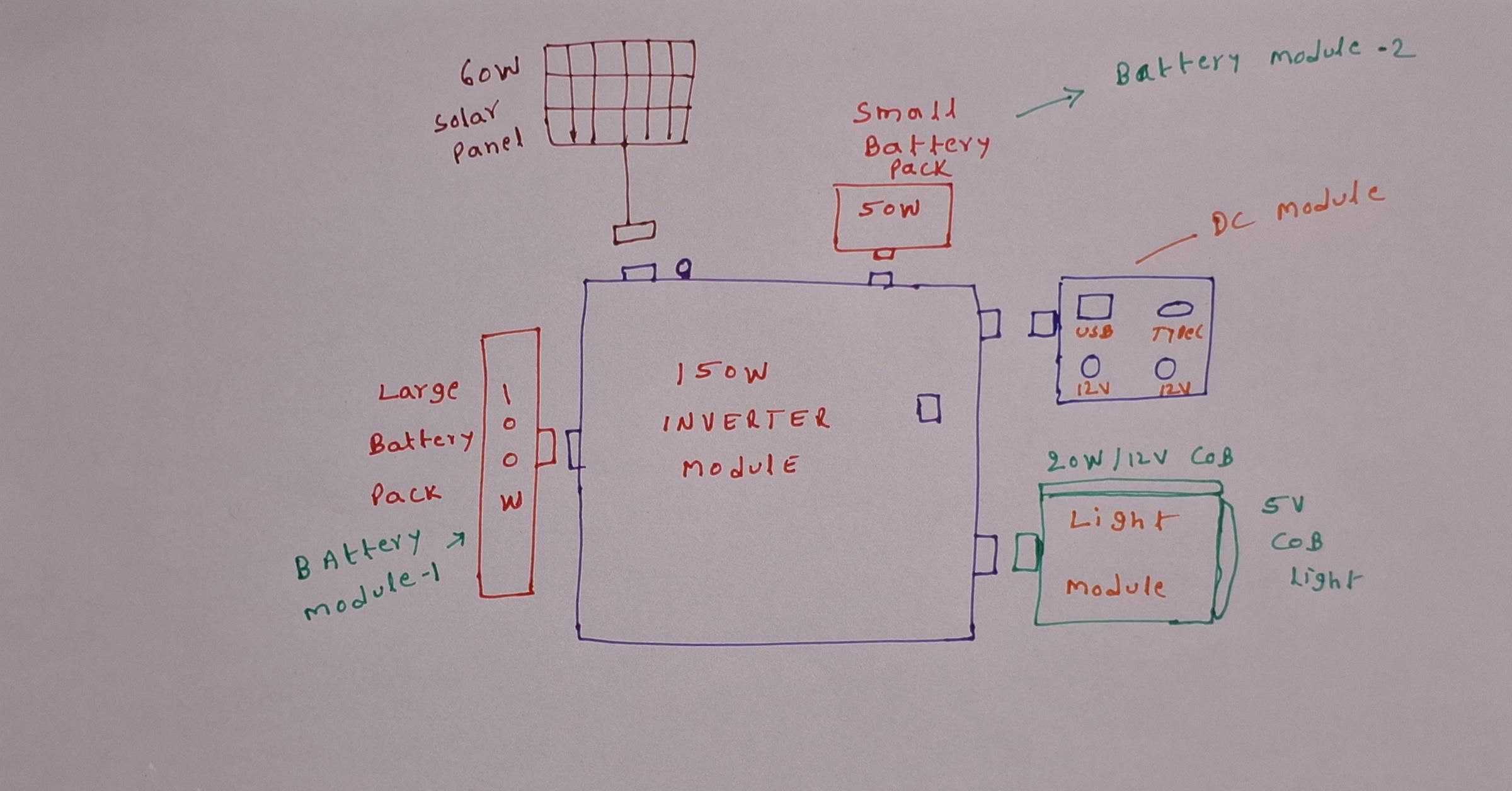
Purpose: Before touching any tools, understand how the four modules relate to the inverter hub.
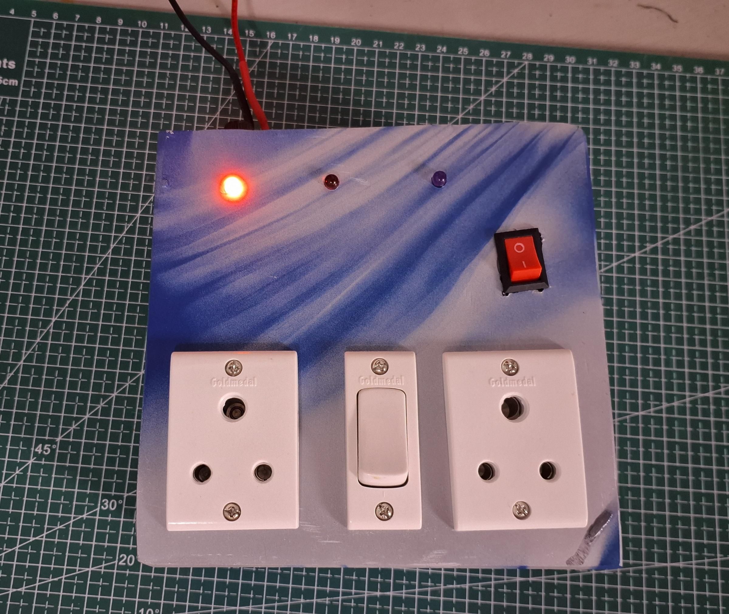
Instructions: The inverter hub is the center of the system. It has five XT60 ports: solar input, large battery (100Wh), small battery (50Wh), DC module, and light module. Every other module connects to the hub, but the DC and light modules can also run directly from a battery module without the hub.
Engineering Note: Keeping the hub central (rather than daisy-chaining modules to each other) means any single module can be removed without breaking the connection between the others.
Common Mistakes: Assuming the light or DC module needs the inverter module present — it does not; both can run on a battery pack alone.
Tip: Sketch the module layout on paper before wiring anything.
Warning: Not Applicable
Gather and Inspect Components
Purpose: Confirm every part is present and undamaged before assembly begins.
Instructions: Lay out every electronic and mechanical part from the Supplies list. Check the 21700 cells for physical damage or swelling before use — never use a damaged lithium cell. Confirm the inverter board and buck converter power on correctly using a bench supply if available.
Engineering Note: Testing each major component individually before final assembly isolates faults early, before they are buried inside a sealed module.
Common Mistakes: Skipping the individual component test and only discovering a dead part after full assembly.
Tip: Label each XT60 connector's intended module with tape as you unpack, to avoid mixing them up later.
Warning: Never use a swollen, punctured, or physically damaged lithium cell.
Build the Small Battery Pack (3S1P)
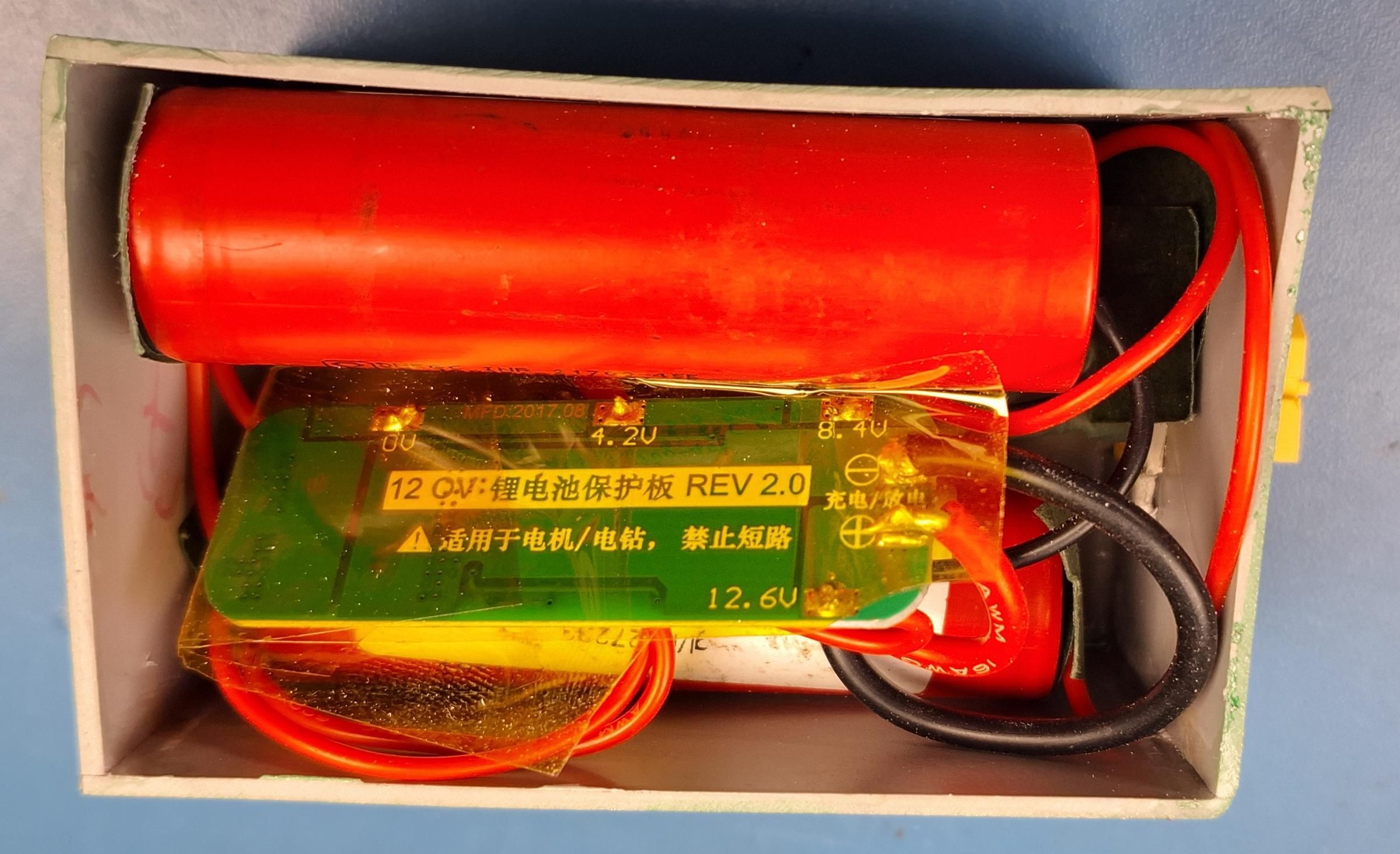
Purpose: Assemble the 50Wh battery pack used for short-duration or lightweight tasks.
Instructions: Arrange 3 × 21700 cells in series (3S1P). Confirm polarity with a multimeter before making any permanent connection. Connect cells in series to reach a nominal 3S voltage, then attach leads that will terminate in an XT60 connector.
Engineering Note: A 3S configuration was chosen because it aligns with the 12.6V full-charge target used later by the buck-converter charging circuit (Step 11).
Common Mistakes: Reversed cell polarity; skipping the multimeter voltage check before final connection.
Tip: Insulate each cell-to-cell joint with heat-shrink immediately after soldering, before moving to the next joint.
Warning: Never short the pack terminals — keep an insulating barrier between the pack and any metal surface while working.
Terminate and Test the Small Battery Pack
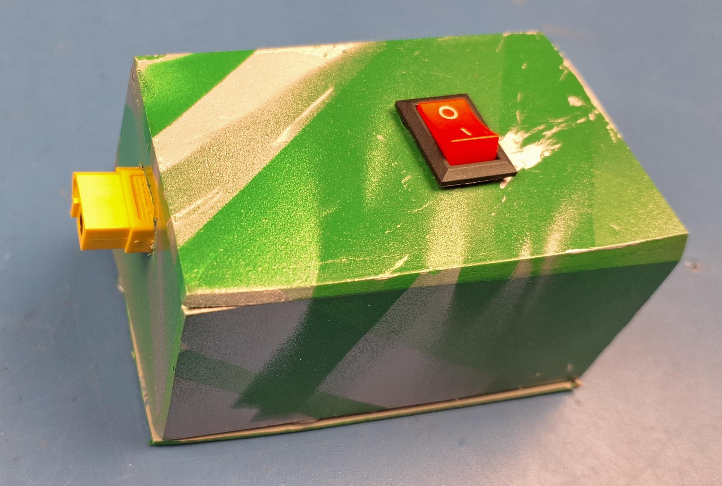
Purpose: Finish the small pack with its XT60 connector and confirm correct output voltage.
Instructions: Solder the pack's positive and negative leads to an XT60 connector, matching polarity to the rest of the system. Measure the pack's open-circuit voltage with a multimeter and confirm it matches the expected 3S nominal range.
Engineering Note: Confirming voltage and polarity here — before this pack ever touches another module — prevents a wiring mistake from propagating into the DC, light, or inverter modules.
Common Mistakes: Reversed XT60 polarity; not verifying voltage before first connection to another module.
Tip: Mark the connector body with "SMALL – 50Wh" so it's never confused with the large pack in the field.
Warning: Double-check polarity before ever plugging this pack into the hub.
Build the Large Battery Pack (3S2P)
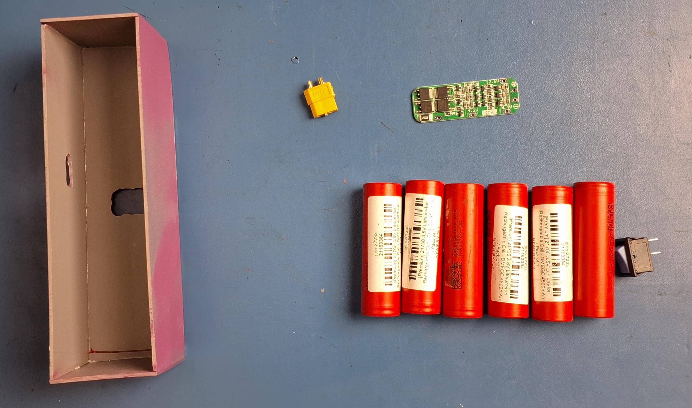
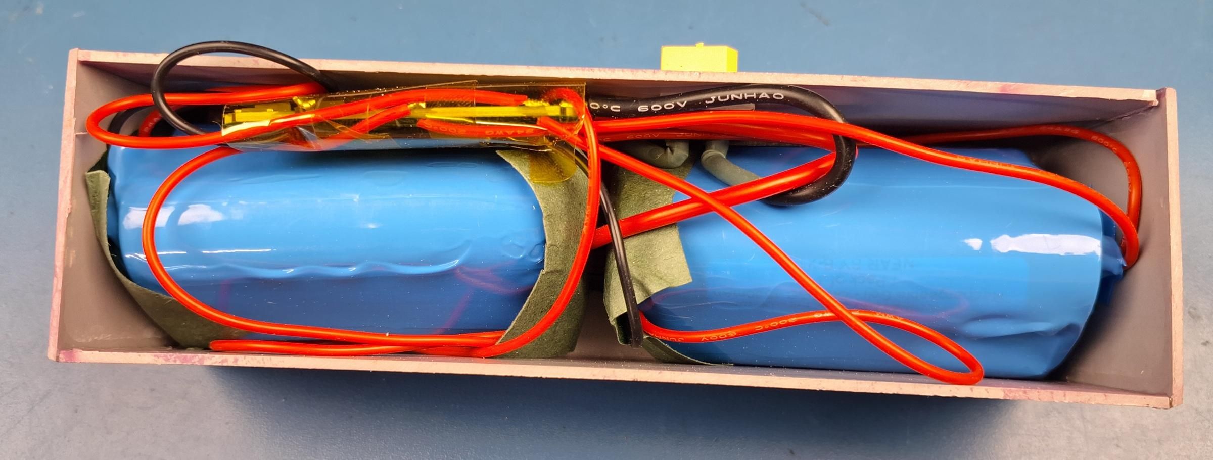
Purpose: Assemble the 100Wh battery pack for longer or higher-demand tasks.
Instructions: Arrange 6 × 21700 cells into a 3S2P configuration — two cells in parallel at each of the three series positions. Confirm each parallel pair is matched in voltage before joining them, then connect the three series stages exactly as in Step 3.
Engineering Note: Doubling the parallel cell count doubles capacity (50Wh → 100Wh) while keeping the same series voltage as the small pack, so both packs remain interchangeable across every other module.
Common Mistakes: Joining cells in parallel without first confirming they are at a similar voltage, which can cause a large inrush current between them.
Tip: Charge or discharge individual cells to a matched voltage before joining them in parallel, if they come from mixed batches.
Warning: Never join lithium cells in parallel without checking their voltages are close to each other first.
Terminate and Test the Large Battery Pack

Purpose: Finish the large pack with its XT60 connector and confirm correct output voltage.
Instructions: Solder the large pack's leads to an XT60 connector, matching polarity convention used for the small pack. Measure voltage and confirm it is consistent with the small pack's reading (same series count, same nominal voltage).
Engineering Note: Keeping both packs at the same nominal voltage is what allows either one to plug into any of the hub's battery ports interchangeably.
Common Mistakes: Small differences in wiring polarity convention between the two packs.
Tip: Mark this connector "LARGE – 100Wh" for quick field identification.
Warning: Confirm polarity before first connection to any other module.
Assemble the DC Module
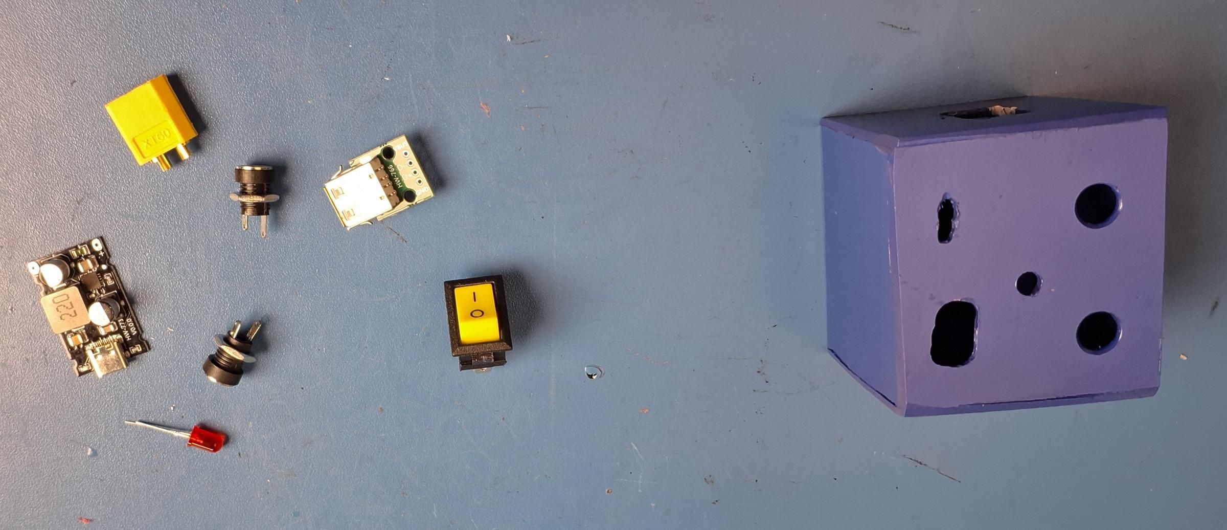
Purpose: Build the module that provides 12V DC and Type-C 65W fast charging.
Instructions: Mount the two 12V DC jacks, the Type-C 65W fast-charging circuit, and the on/off switch inside the DC module enclosure. Wire all three in parallel to a common input, then wire that input through the switch to an XT60 connector.
Engineering Note: Putting a single switch upstream of every output lets the whole module be turned off without unplugging it from the battery, useful when the module is idle but still connected.
Common Mistakes: Wiring the switch after the fast-charging circuit instead of before it, which would leave the charging circuit powered even when "off."
Tip: Test the Type-C fast-charging circuit with a known device before final enclosure assembly.
Warning: Confirm the Type-C circuit's input voltage range matches the battery pack's voltage before first use.
Test the DC Module Independently
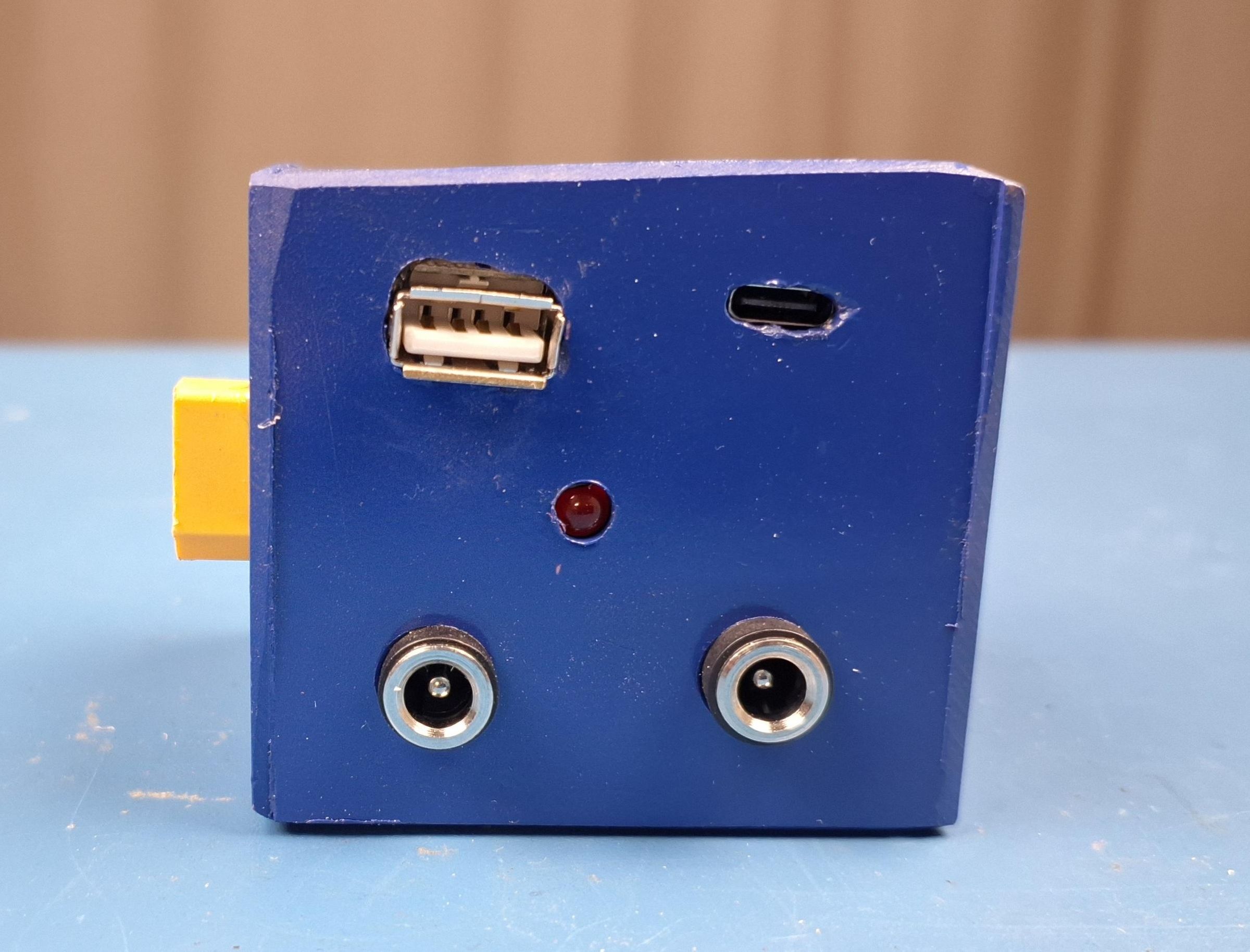
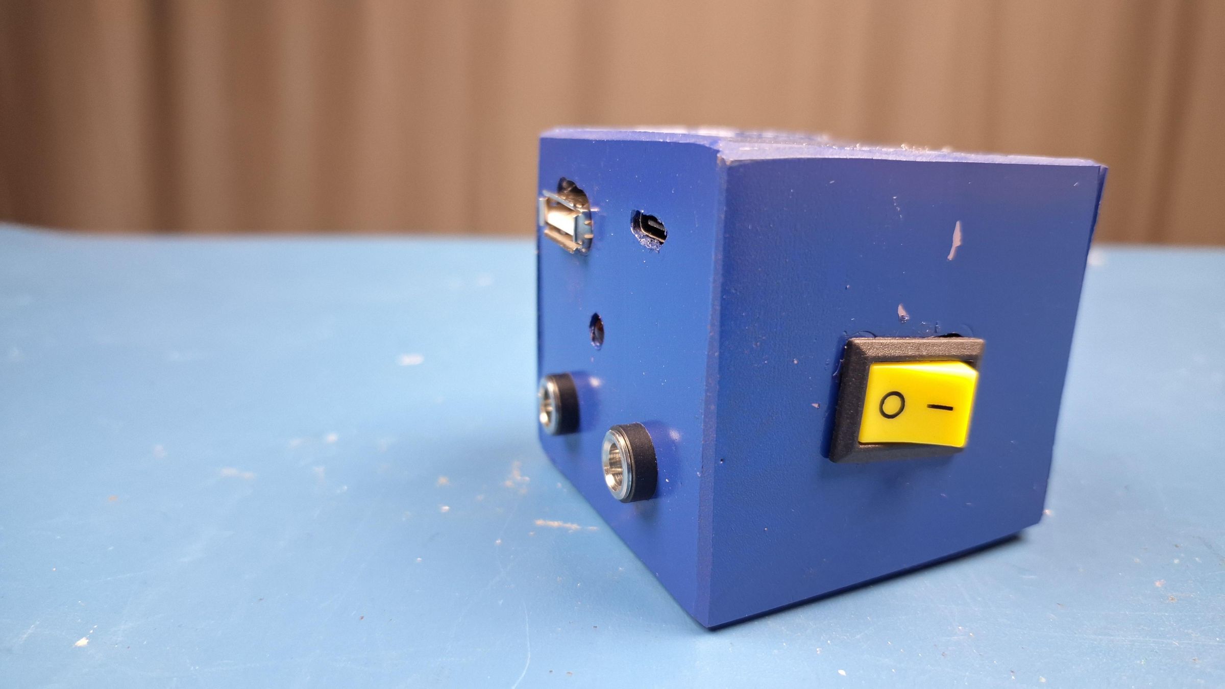
Purpose: Verify the DC module works correctly before it is ever connected to the rest of the system.
Instructions: Connect the finished DC module directly to one of the battery packs. Confirm both 12V DC jacks output the expected voltage, and confirm the Type-C port charges a test device.
Checkpoint: Both DC jacks should read approximately the battery pack's voltage. The Type-C port should register a charging connection with a test device. If not, check wiring before continuing.
Engineering Note: Testing this module stand-alone (battery + DC module only, no hub) proves the "independent operation" design goal actually works.
Common Mistakes: Testing only one output and assuming the others work.
Tip: Test with the switch in both positions to confirm it fully isolates the module.
Assemble the Light Module
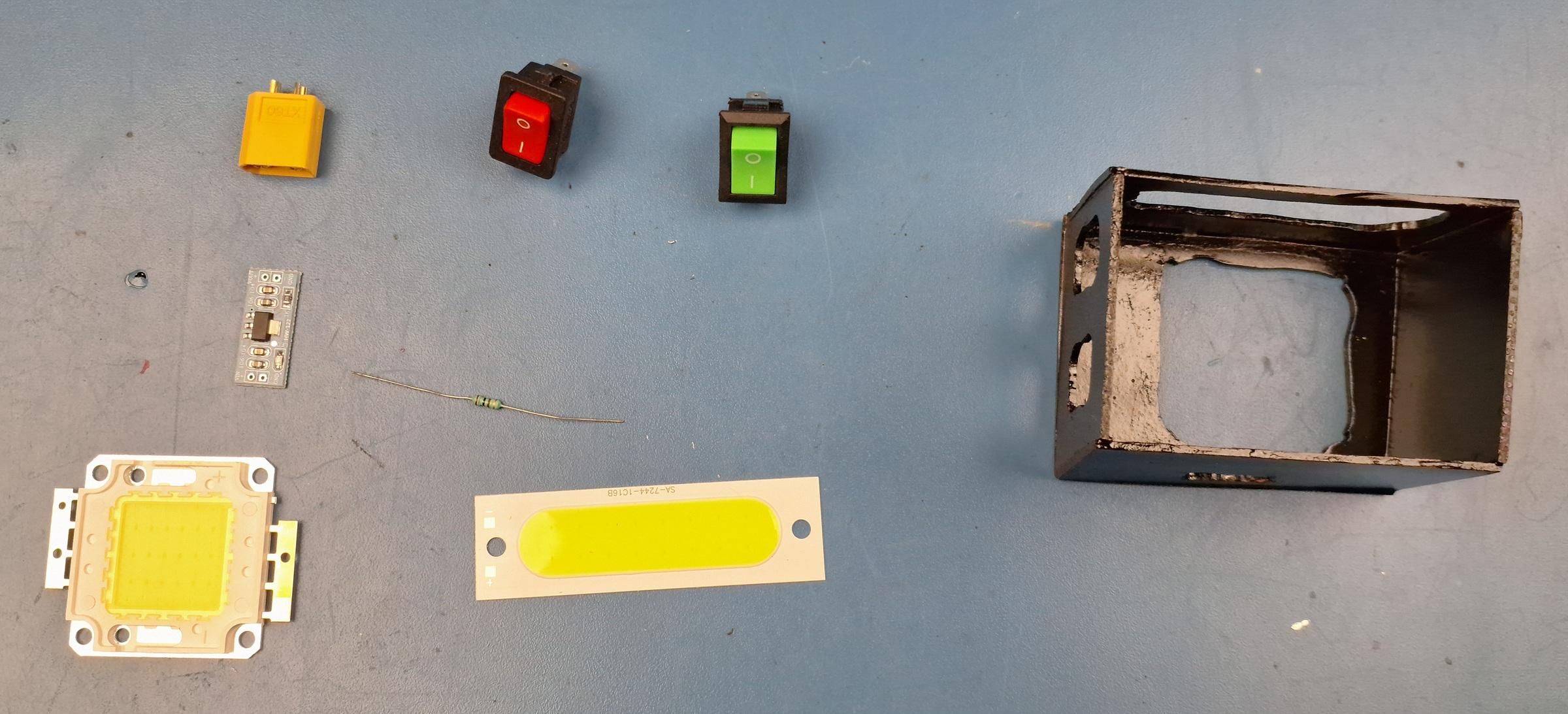
Purpose: Build the module containing the 12V/20W COB light and the 5V COB light.
Instructions: Mount the 12V/20W COB light and wire it through its own switch directly to the module's XT60 input. Mount the 5V COB light, and wire its supply through the 12V-to-5V step-down module before its own independent switch.
Engineering Note: Running the 5V light through a dedicated step-down module (rather than sharing a converter with anything else) keeps the two lights fully independent, so one can be used without powering the other's converter circuit.
Common Mistakes: Wiring both lights to a single shared switch, which removes the ability to run only one light at a time.
Tip: Test each light's brightness separately before final enclosure assembly to confirm the step-down module is outputting a clean 5V.
Test the Light Module Independently
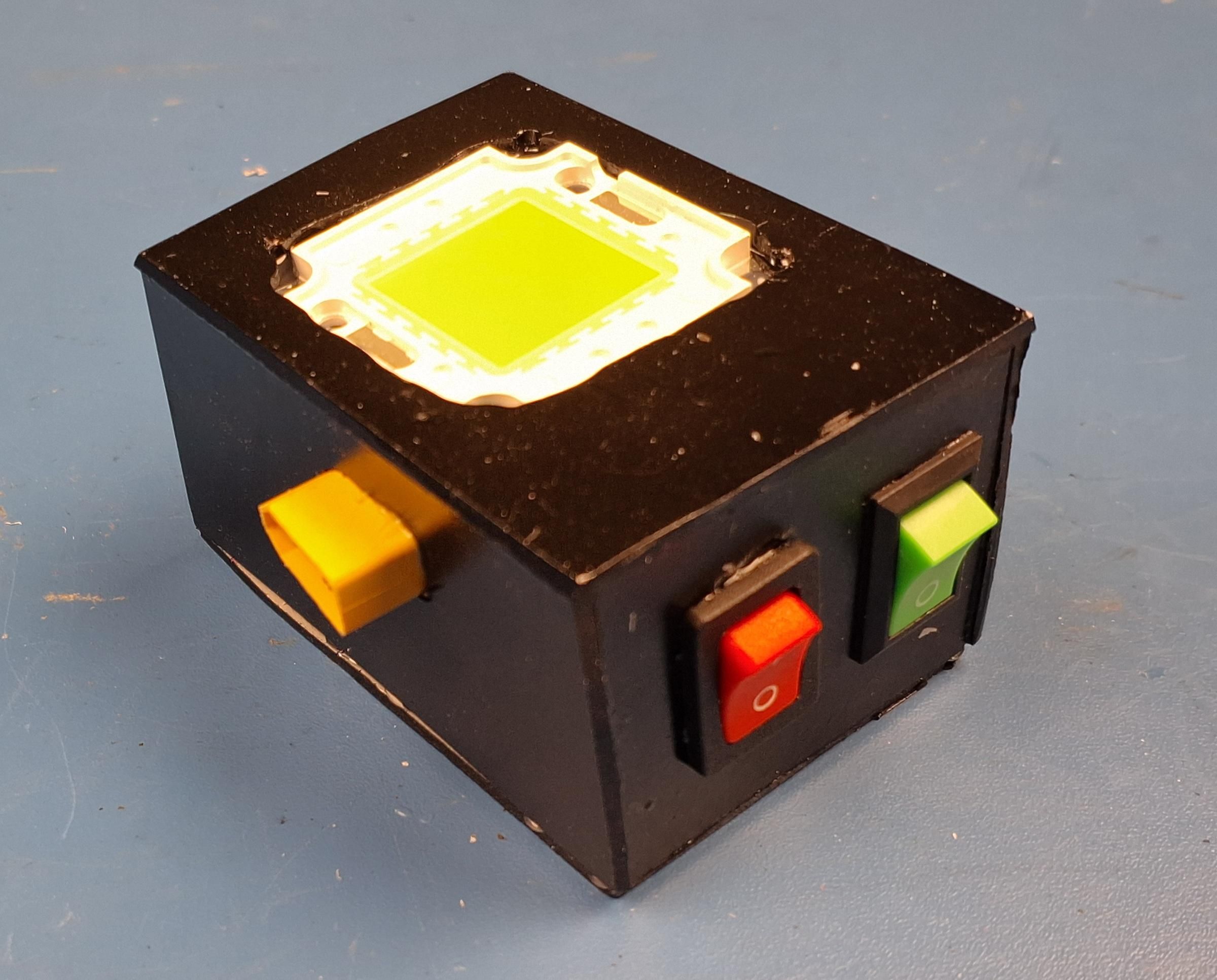
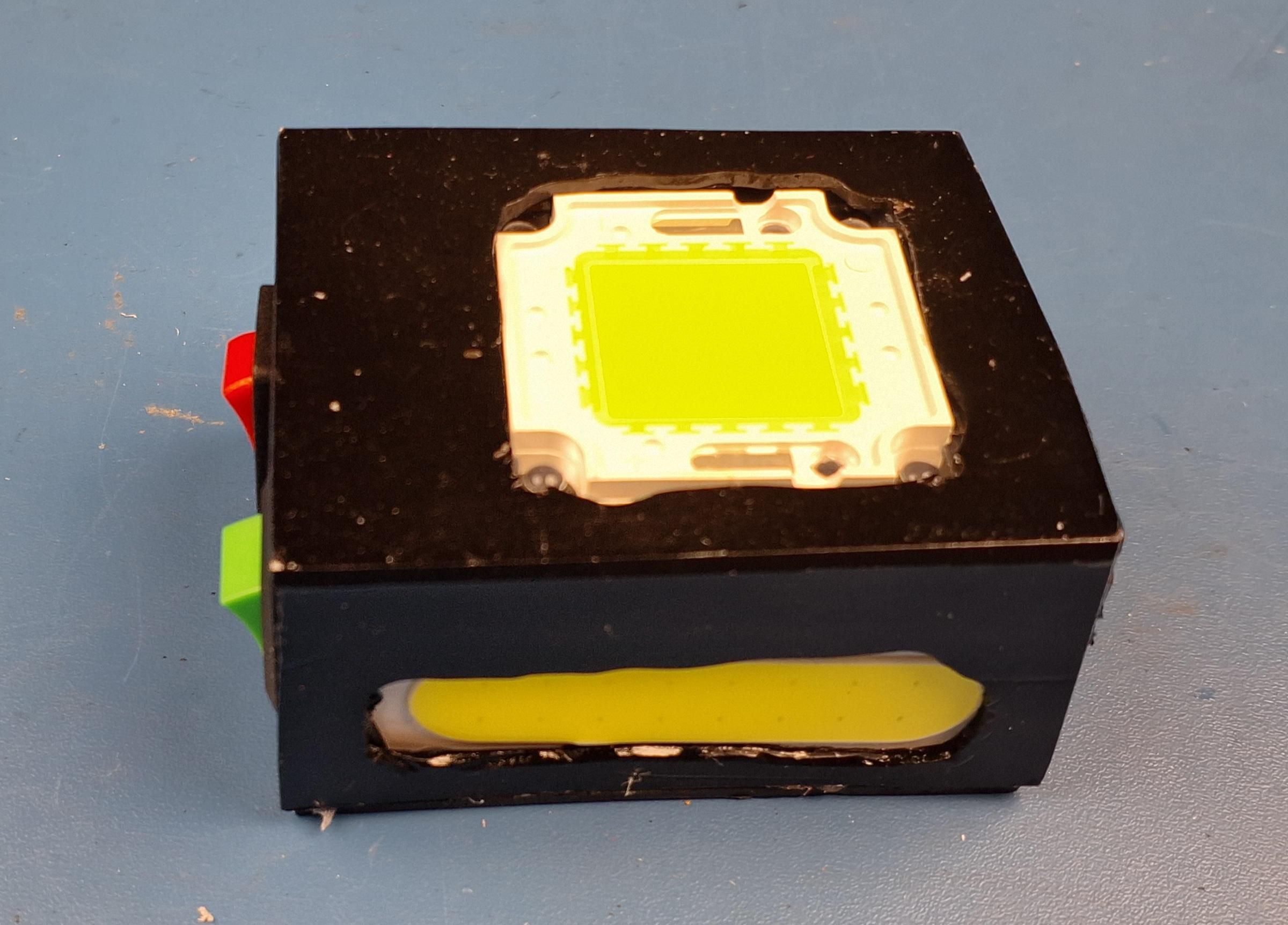
Purpose: Confirm both lights work correctly and independently before connecting the rest of the system.
Instructions: Connect the light module directly to a battery pack. Switch on the 12V/20W COB light alone and confirm it lights. Switch it off, then switch on the 5V COB light alone and confirm it lights, and measure its supply voltage at approximately 5V with a multimeter.
Checkpoint: Each light should switch on independently of the other. The 5V light's step-down output should measure close to 5V. If not, check wiring before continuing.
Engineering Note: This checkpoint directly verifies the "separate light module for night walking/working" use case from the project's design goals.
Common Mistakes: Assuming both lights work because one does.
Tip: Not Applicable
Warning: COB lights can become warm during extended operation — allow the module to cool before closing the enclosure.
Set Up the Inverter Hub's Charge Circuit
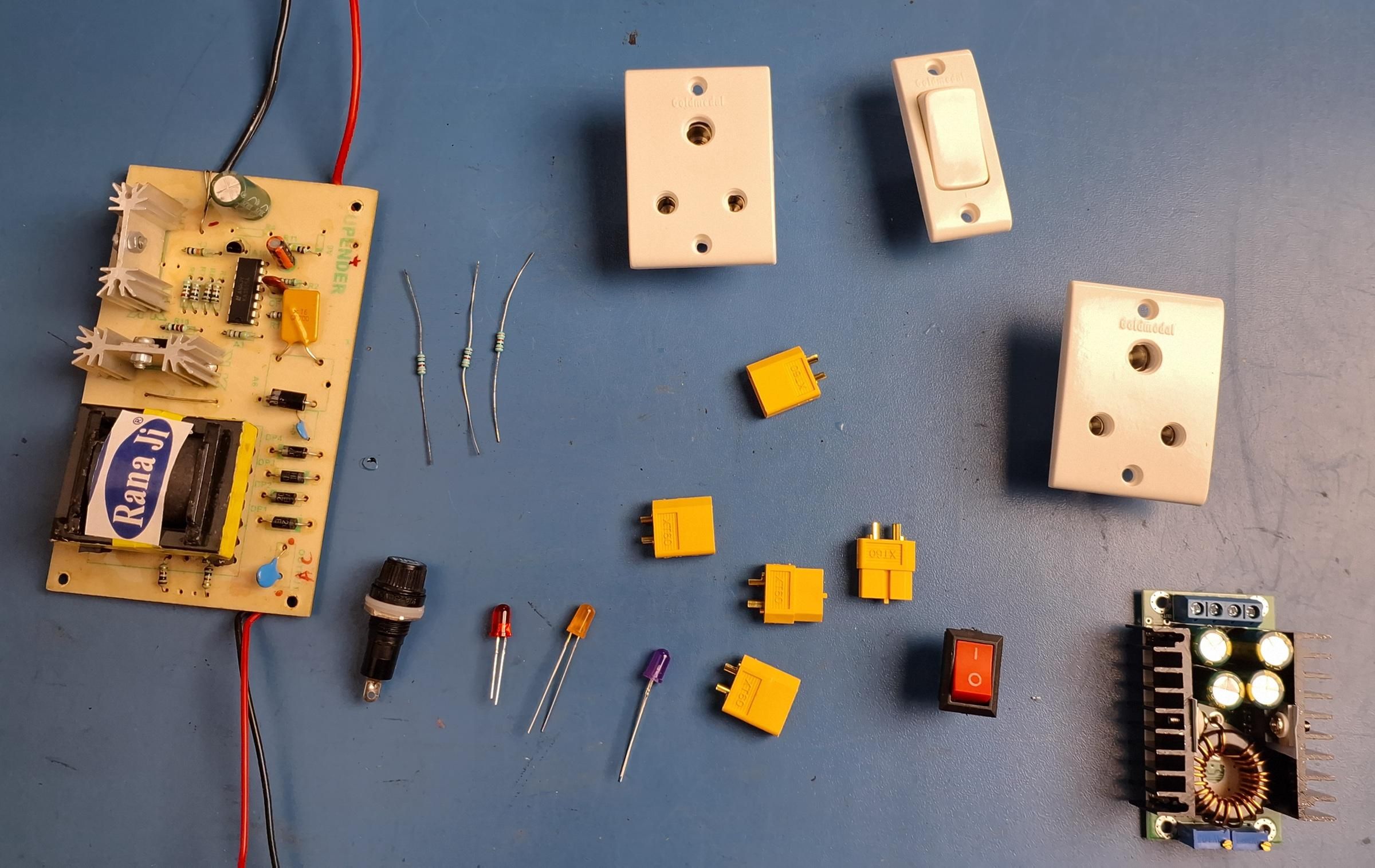
Purpose: Configure the buck converter to safely charge the 3S battery packs.
Instructions: Wire the 300W buck converter's input to the solar panel connection point on the hub. Set the buck converter's output voltage to 12.6V measured after the protection diode (i.e., set the converter itself slightly above 12.6V to compensate for the diode's approximate 0.7V forward-voltage drop). Confirm the final measured voltage at the battery connection point is 12.6V using a multimeter before connecting any battery pack.
Engineering Note: A dedicated lithium/21700 charge-controller IC was not used here; instead, the existing buck converter (needed anyway for solar step-down) is set to the correct fixed full-charge voltage for a 3S pack, with a series diode added for protection. This is a simpler, lower-cost approach, with the trade-off of no active cell balancing — see the Conclusion for the limitations of this method.
Common Mistakes: Setting the buck converter to exactly 12.6V and forgetting to compensate for the diode's voltage drop, which would undercharge the pack.
Tip: Verify the final voltage with a multimeter directly at the battery XT60 port, not just at the buck converter's own output terminals.
Warning: Confirm the charge voltage is correct before connecting any battery pack — an incorrect voltage can overcharge or damage lithium cells.
Wire the Inverter Hub's Five XT60 Ports
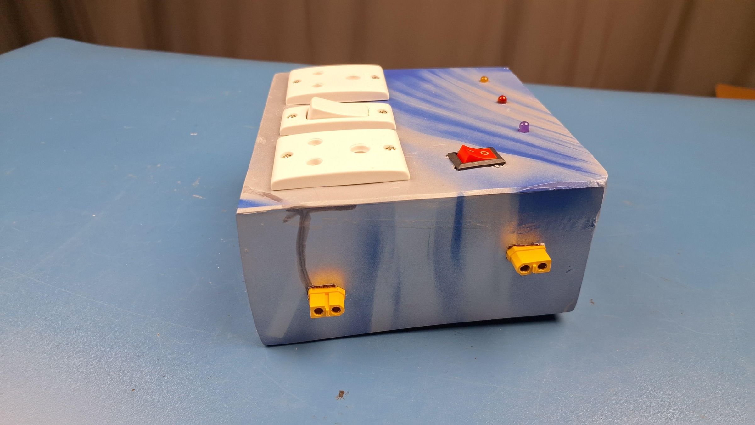
Purpose: Connect the solar input, large battery, small battery, DC module, and light module ports to the hub's internal wiring.
Instructions: Wire each of the five XT60 connectors to its corresponding internal node: solar input to the buck converter input, large and small battery ports to the shared battery bus, and DC/light module ports to the same shared battery bus (downstream of the inverter's main input). Keep polarity consistent across every port.
Engineering Note: Using one shared battery bus for both battery ports means either the small or large pack (or both, if used at different times) can supply the entire hub without rewiring anything.
Common Mistakes: Mixing up polarity between the solar input port and the battery ports — these must not be interchangeable.
Tip: Physically separate or clearly label the solar input connector from the battery connectors, since plugging a battery into the solar input (or vice versa) could damage the system.
Warning: Never connect a battery pack to the solar input port.
Install the Safety Fuse
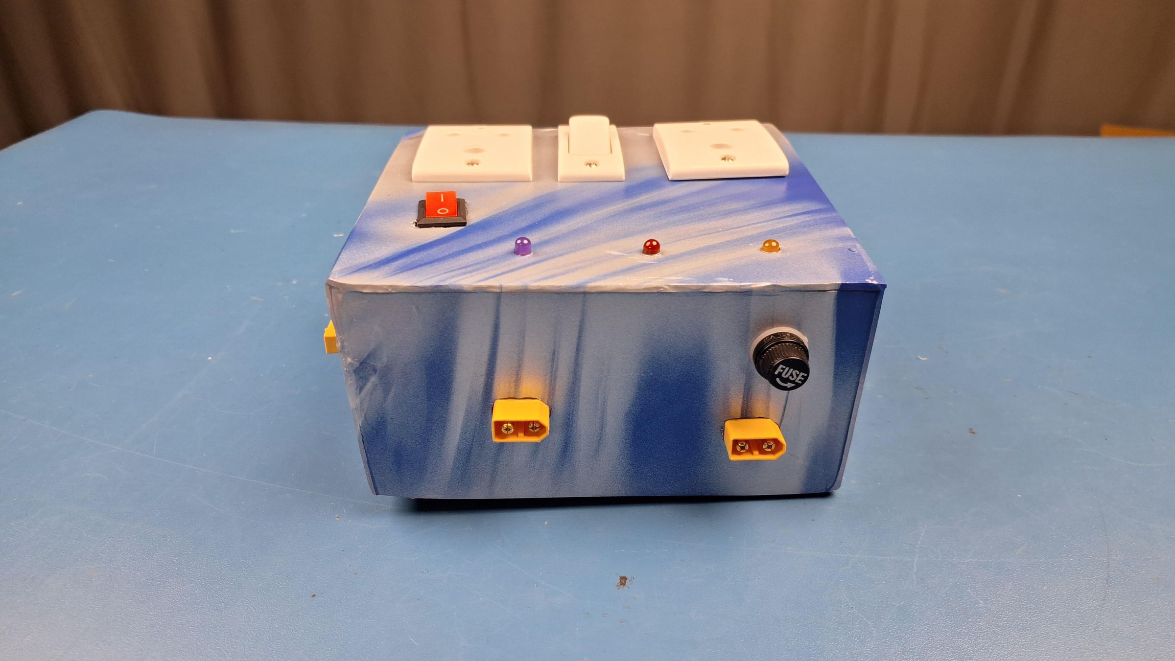
Purpose: Add overcurrent protection to the inverter hub.
Instructions: Install the inline fuse in series with the main battery bus, between the battery XT60 ports and the 150W inverter circuit.
Engineering Note: Placing the fuse on the shared battery bus (rather than on each individual port) protects the whole hub with a single, easily-replaceable component.
Common Mistakes: Placing the fuse after a branch point instead of before it, which would leave part of the circuit unprotected.
Tip: Choose a fuse rating based on the maximum expected current draw of the 150W inverter circuit plus a safety margin.
Warning: Never bypass or oversize the fuse beyond what the wiring and components are rated for.
Mount the 150W Inverter Circuit
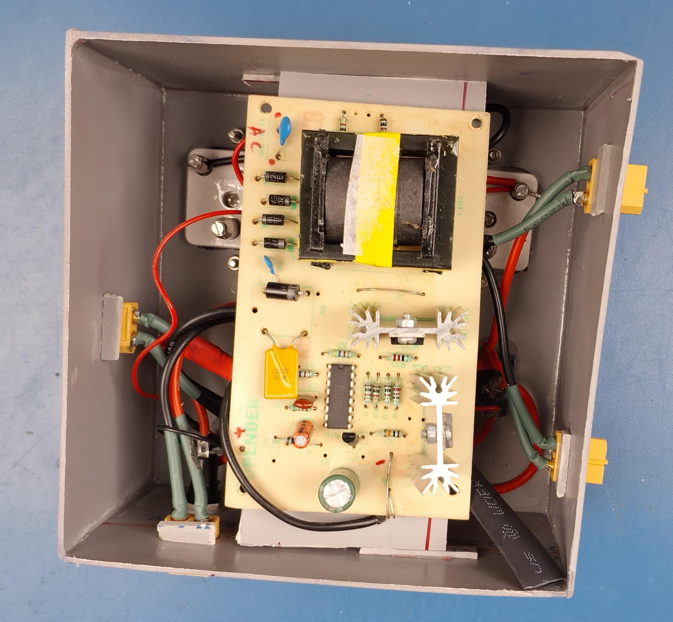
Purpose: Install the inverter board that provides AC output from the hub.
Instructions: Mount the 150W inverter board inside the hub enclosure, downstream of the fuse installed in Step 13. Wire its DC input to the shared battery bus and confirm its AC output connector is accessible from outside the enclosure.
Engineering Note: Placing the inverter downstream of the fuse (not upstream) ensures the fuse protects the inverter itself, not just the modules connected to it.
Common Mistakes: Wiring the inverter input before the fuse instead of after it.
Tip: Leave enough clearance around the inverter board for heat dissipation.
Warning: The inverter output carries AC voltage — treat the output connector with the same care as a mains outlet.
Connect the Solar Panel and Test Charging
Purpose: Confirm the complete charging path works from solar panel to battery pack.
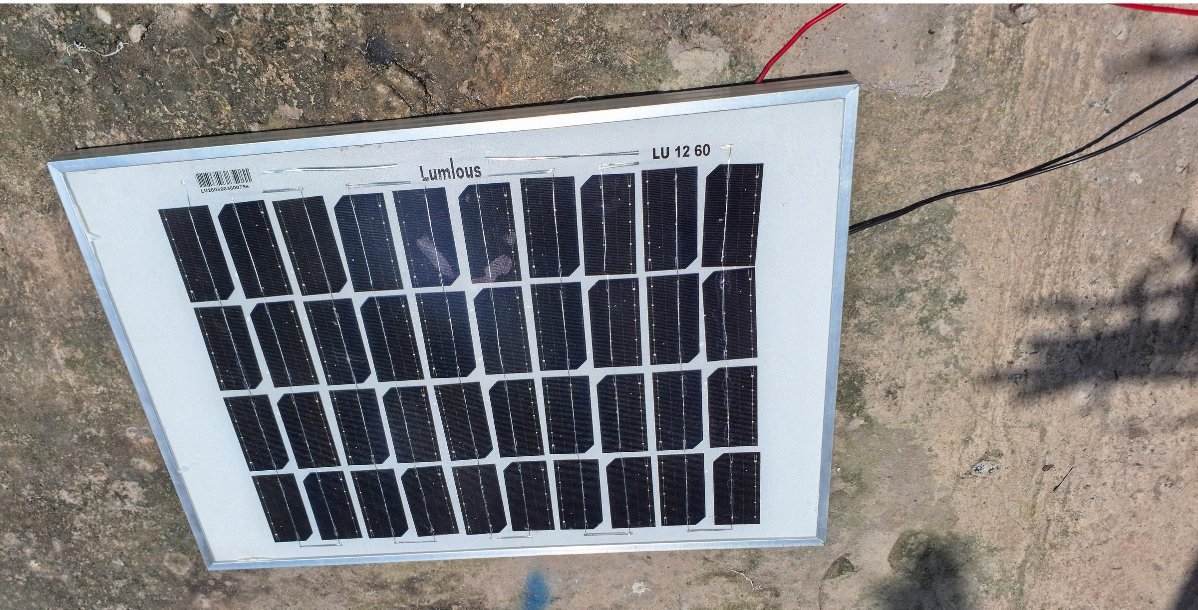
Instructions: Connect the 60W solar panel to the hub's solar input port under sunlight. Connect a battery pack to one of the battery ports. Measure the charge current and voltage at the battery connector to confirm charging is occurring at the expected 12.6V target.
Checkpoint: The battery port should show a rising or steady voltage near 12.6V under sunlight with the panel connected, and no charging activity should occur when the panel is disconnected. If not, check the buck converter setting from Step 11 before continuing.
Engineering Note: Confirming this under real sunlight (not just a bench supply) validates the "fully offline solar inverter" design goal in real conditions.
Common Mistakes: Testing only with a bench power supply and assuming solar performance will match exactly.
Tip: Test at different times of day to understand how panel angle and sunlight intensity affect charge current.
Test the Small Battery Configuration (Night Walking Setup)
Purpose: Verify the light module plus small battery pack configuration described in the project's design goals.
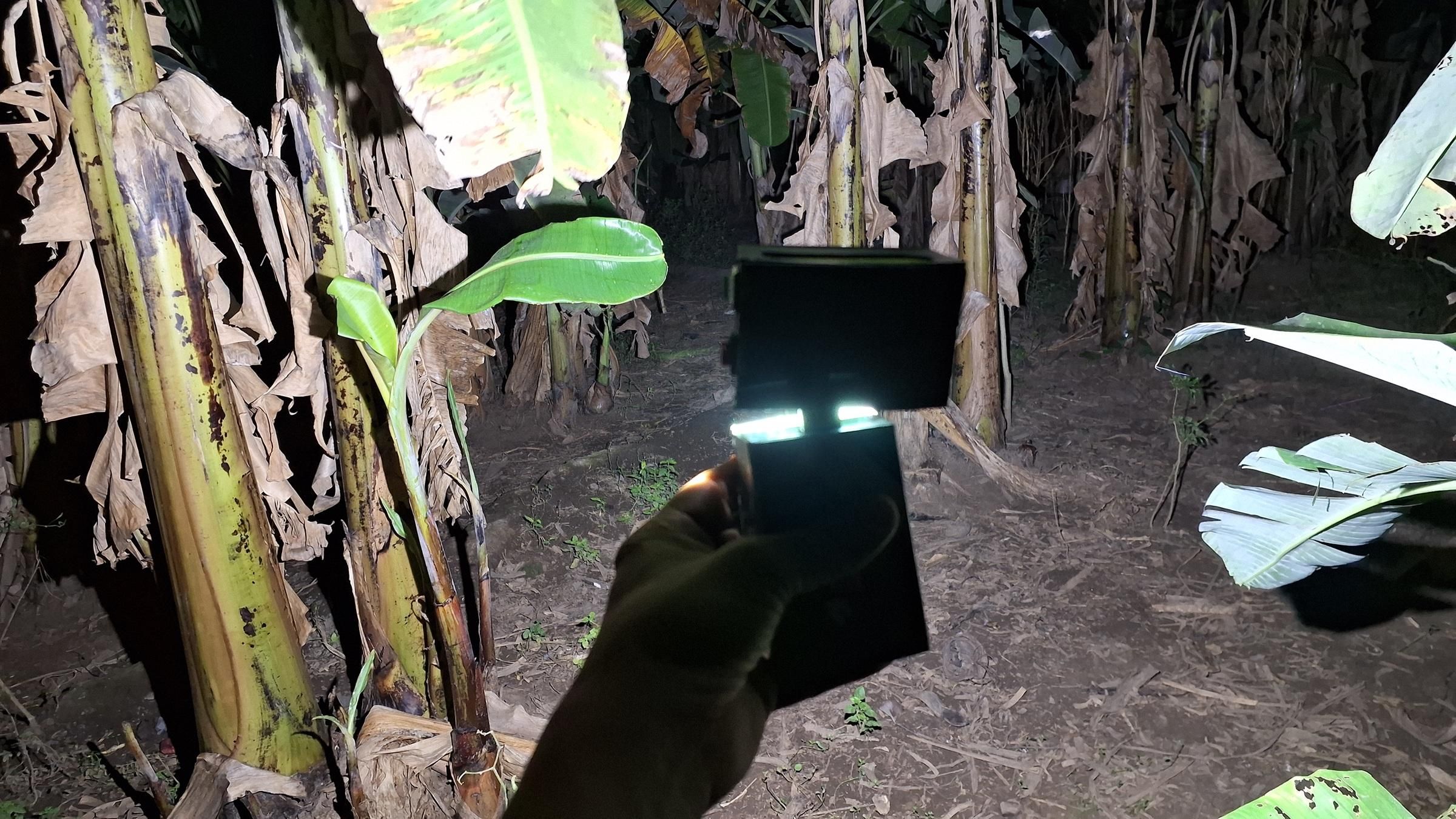
Instructions: Connect only the small (50Wh) battery pack to the light module, with the inverter hub and DC module disconnected. Confirm both lights operate normally in this configuration.
Checkpoint: Both COB lights should work normally with only the small battery pack connected — no other module should be required. If not, recheck the light module's independence from Step 9–10.
Engineering Note: This test directly proves the "at night, separate the light module and battery module for walking/working" use case.
Common Mistakes: Forgetting to fully disconnect the hub before testing, which would not prove independence.
Tip: Time how long the small pack powers the light module at typical brightness, for future reference in the documentation.
Test the DC + Battery Configuration (Field/Vacation Setup)
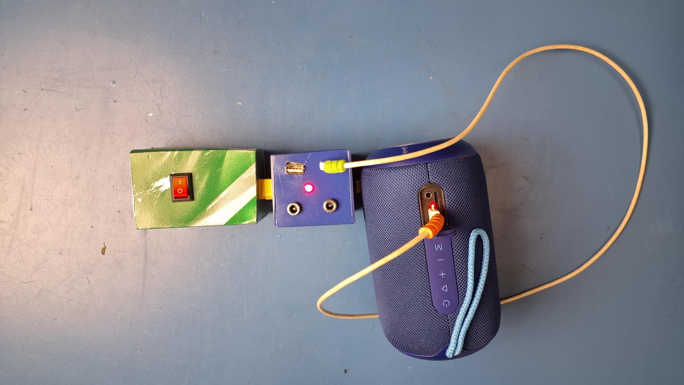
Purpose: Verify the DC module plus battery pack configuration for general remote or vacation use.
Instructions: Connect either battery pack to the DC module alone, with the hub and light module disconnected. Confirm the 12V DC outputs and Type-C fast charging work in this stand-alone configuration.
Checkpoint: Both DC outputs and the Type-C port should function normally with only a battery pack connected. If not, recheck the DC module's independence from Step 7–8.
Engineering Note: This confirms the "battery + DC module useful for vacation or other work" design goal.
Common Mistakes: Testing with the hub still connected, which would not isolate the DC module's independent operation.
Test the Full Assembly (AC Output)
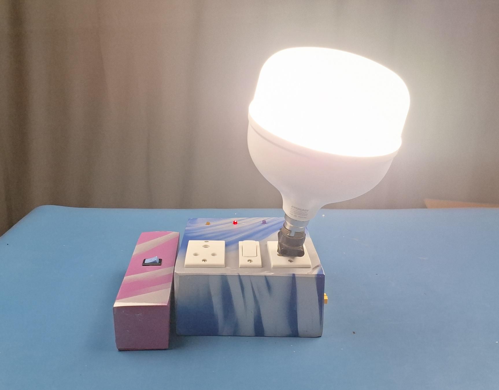
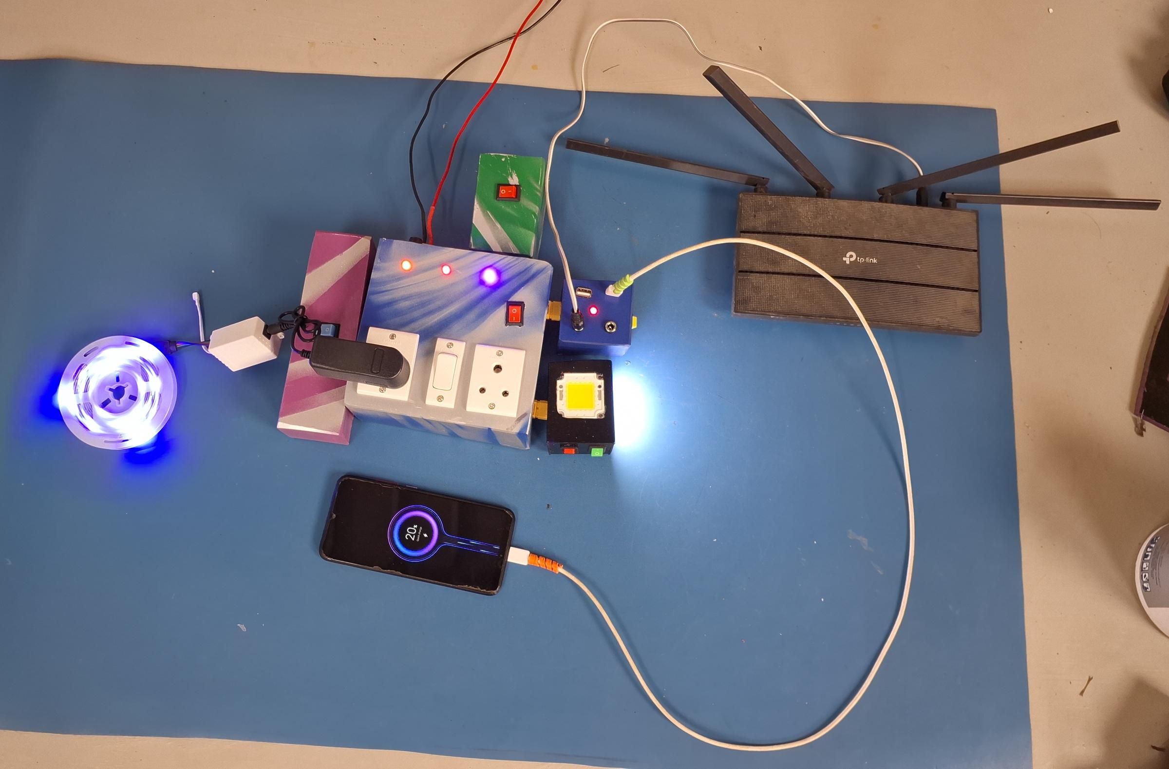
Purpose: Verify the complete system with every module connected to the hub, delivering AC output.
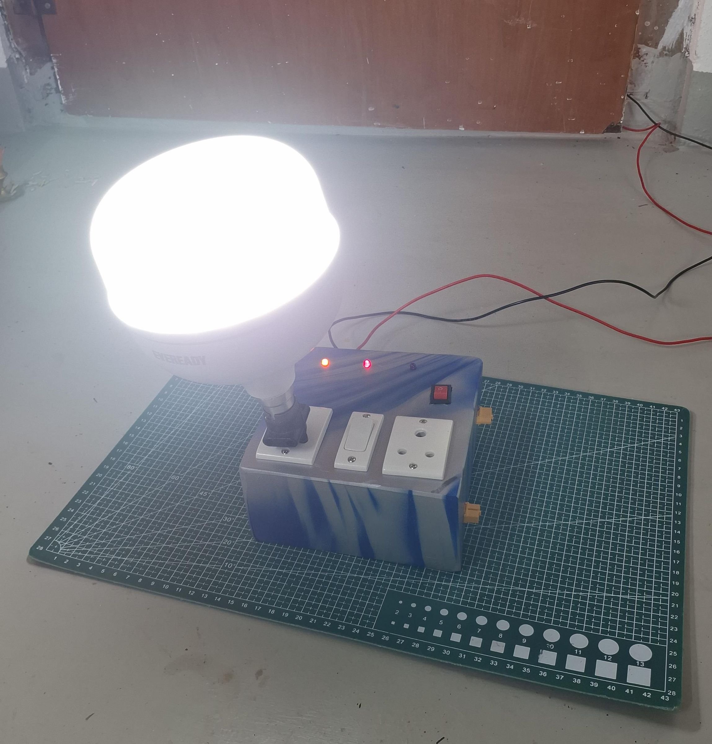
Instructions: Connect a battery pack, the DC module, and the light module to the hub simultaneously. Confirm the inverter's AC output powers a small test load, and confirm the DC and light modules still function normally while connected to the hub.
Checkpoint: AC output should be present at the inverter's output connector, and both other modules should continue to operate normally. If not, recheck the shared bus wiring from Step 12.
Engineering Note: This is the configuration that proves every module can operate simultaneously without interfering with each other, since they share a common battery bus.
Common Mistakes: Overloading the inverter with a load exceeding 150W.
Tip: Start testing with a small, well-understood AC load (such as a lamp) rather than an unknown device.
Warning: Confirm the AC load is within the 150W rating of the inverter circuit before connecting it.
Final Enclosure Assembly
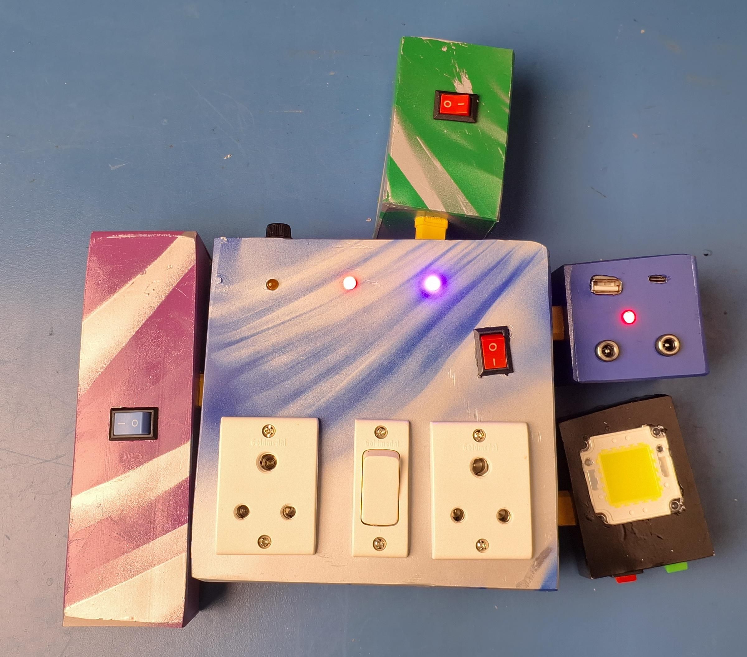
Purpose: Close up each module's enclosure for field use.
Instructions: With every module tested and confirmed working, close and secure each enclosure. Confirm no wires are pinched and every switch and connector remains accessible from outside the enclosure.
Engineering Note: Testing before enclosing (Steps 8, 10, 15–18) means any fault is caught while the wiring is still accessible, rather than after the module is sealed.
Common Mistakes: Closing an enclosure before final testing, requiring it to be reopened if a fault is found.
CONCLUSION
This build shows that a power system does not need to be one fixed device — splitting it into a battery, a DC module, a light module, and an inverter hub around a common XT60 interface means the same batteries can serve completely different jobs depending on what's connected. The buck-converter charging approach used here (Step 11) keeps the design simple and low-cost, but it has a real limitation worth being honest about: it has no active cell balancing, unlike a dedicated lithium BMS. For this build's scale, careful voltage matching during assembly (Steps 3–6) is the mitigation; a future version could add a proper charge-controller IC for larger packs or higher-current use.
If you build this, the most useful thing you can change is the battery configuration — the same modular approach works with different cell counts or capacities as long as every pack is kept at the same nominal voltage.