Pot Lid Steam Generator
Introduction
Steam turbine generation is the backbone of modern electricity production — used in nuclear plants, coal and gas plants, and even cutting-edge concentrated solar plants that use mirrors to boil water. If a fire, a nuclear reaction, or the sun can all be reduced to "heat a fluid, spin a turbine, generate electricity," then in principle any heat source can be turned into a small amount of electrical power.
This project asks: why not make that portable? Using the methodology in this Instructable, any campfire can become a real source of electrical power.
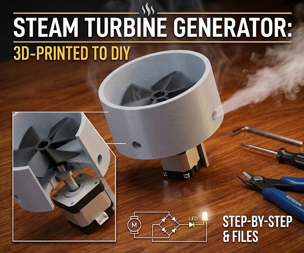
Parts designed in a mix of solidworks and Fusion 360.
History: From Alexandria to the Power Grid
The idea of turning heat into rotary motion is nearly 2,000 years old, and tracing that history shows why turbines eventually won out over almost every other way of doing it.
The first steam turbine (~1st century AD): The earliest known device is Hero of Alexandria's aeolipile — a sealed sphere of water suspended over a fire, with two bent nozzles that let steam escape and push the sphere into rotation by jet reaction. It's the same basic principle used in this project: steam escaping through a nozzle produces a reaction force that can be converted into spin. In Hero's time it was treated as a curiosity or toy, not a source of useful work — nobody yet needed rotary power badly enough to develop it further.
The reciprocating engine era (1700s–1800s): It took over 1,600 years for steam to be harnessed for real work, and when it was, it was via reciprocating engines — pistons, not turbines. Thomas Newcomen's atmospheric engine (1712) pumped water out of mines using a piston driven by condensing steam. James Watt's improvements (from 1776) — most importantly the separate condenser — made steam engines efficient enough to power the Industrial Revolution: textile mills, locomotives, and ships. These engines converted heat to linear motion first, then to rotary motion via a crank — an extra, lossy step that limited how fast (and how efficiently) they could run.
The turbine breakthrough (1884): Charles Parsons changed this by inventing the first practical steam turbine, which extracted energy from steam directly as rotary motion — no pistons, no cranks, no reciprocating losses. His multi-stage turbine could spin much faster than any piston engine, and in 1897 he proved it dramatically by gate-crashing a British naval review with his experimental turbine-powered boat, Turbinia, which outran every warship in the fleet. Within a decade, turbines had replaced piston engines in most large-scale power generation and marine propulsion. This is the direct ancestor of the small rotor used in this project.
Why turbines won: A rotary system has no reciprocating parts to slam back and forth, so it can spin far faster with far less vibration and mechanical loss. Faster spin means more power for a given size — the same reason a dentist's drill outperforms a hand crank. This is also why the tip-speed and RPM numbers in the calculations below matter so much: turbines only become efficient at high rotational speed, which is exactly what makes them mechanically demanding (and, as covered below, dangerous) at small scale.
The 20th century — steam scales up: Once turbines were established, the heat source driving the steam became almost interchangeable. Coal and gas boilers, and later nuclear reactors, all do the same job Hero's fire did: boil water to make steam, and let a turbine convert that steam into rotation. This is the Rankine cycle, and it remains the basis of roughly 80–90% of the world's electricity generation today.
Concentrated solar power (modern day): The newest chapter in this history doesn't burn anything at all. Concentrated solar power (CSP) plants use fields of mirrors (heliostats) to focus sunlight onto a central receiver, heating a fluid to boil water — driving an ordinary steam turbine exactly like a coal plant would. It's a striking illustration of the core idea behind this project: the turbine doesn't care where the heat comes from. Fire, fission, or focused sunlight — if it makes steam, it can make electricity.
This project, in that lineage: A soda can, some plastic air hose, and a hobby motor scavenged as a generator is a very long way from a nuclear plant or a Parsons turbine — but it is mechanically the same idea Hero demonstrated two millennia ago: heat a sealed vessel, let steam escape through a nozzle, and capture the resulting rotation. Shrinking that idea down to something portable is really shrinking down the entire history of steam power into something you could carry in a backpack.
from claud.ai
The Dangers
This build uses real pressure and real heat, so please read this section as seriously as the maths section below.
- Pressure vessel: A pot lid is used here which is safe but using another type of pressureised container can be dangerous and should be done with caution. Ensure there is a pressure relief to avoid a steam explosion.
- Plumbing: This build uses plastic air hose simply because it was on hand. Plastic is a poor choice for a heated, pressurised steam line, it can soften, deform, or fail. A brass pipe or a metal-braided hose rated for high-temperature steam would be a far safer and more appropriate choice.
- Fire: This project involves an open flame throughout. Observe normal fire safety at all times, clear surroundings, a means to extinguish, and never leave it unattended.
- Rotating parts: High-speed turbines are dangerous in their own right, independent of the heat and pressure, I found this out first-hand by slicing my thumb on the spinning rotor. Keep hands, hair, and loose clothing well clear while it's running.
The Maths
Turbine geometry
- Diameter: D = 0.05 m
- Radius: r = 0.025 m
- Height: h = 0.02 m
- Rotor area: A = πr² = 1.96 × 10⁻³ m²
- Rotor volume (approx.): A × h = 3.93 × 10⁻⁵ m³
Rotor tip speed vs. RPM
RPM| Tip speed
5,000 | 13.1 m/s
10,000 | 26.2 m/s
20,000 | 52.4 m/s
Hobby motor used as a generator
RPM | Output voltage
5,000 | 1–2 V
10,000 | 2–4 V
20,000 | 4–8 V
Rotational inertia (resistance to spinning up)
I = 0.5 × m × r² = 3.1 × 10⁻⁶ kg·m²
Kinetic energy stored in the spinning rotor at 20,000 RPM
E = 0.5 × I × (2πN/60)² ≈ 13.7 J
This is a similar order of magnitude to the energy stored in the motor's rotor when it's driven electrically as a motor rather than turned mechanically as a generator, a useful sanity check that the numbers are in the right ballpark.
Pressure vs. temperature (why this is not a linear problem)
A genuinely interesting (and counter-intuitive) result from the steam tables is that saturation pressure does not rise linearly with temperature:
- 100 °C → 120 °C increases pressure by about 98 kPa
- 180 °C → 200 °C increases pressure by more than 500 kPa
The same 20 °C step produces a wildly different pressure jump depending on where you are on the curve. This is why steam tables, standard reference data in thermodynamics and fluid dynamics, are essential rather than optional here; you cannot linearly extrapolate steam behaviour from a couple of data points.
Power from enthalpy drop
P = ṁ(h₁ − h₂)
Where:
- ṁ is the mass flow rate of steam (kg/s)
- h₁, h₂ are the specific enthalpies (a thermodynamic property representing the total heat content of the steam) at inlet and outlet
This equation is the real bridge between "how hot and pressurised is my steam" and "how much power can I actually extract" it's the formula every full-scale steam turbine is fundamentally sized around.
Torque
τ = F × r
With turbine radius r = 0.025 m and an assumed steam jet force of F = 2 N: τ = 2 × 0.025 = 0.05 N·m
The energy transfer chain
Heat → steam energy → jet kinetic energy → rotor mechanical power → generator electrical power
Every stage in this chain loses energy — to absorbed heat, friction, aerodynamic drag, electrical resistance, and more, so only a small fraction of the original heat energy survives as electricity. Practically, this means the water must be heated substantially and the pressure must be kept high to get anything electrically meaningful out the other end.
Stress on the rotor
Because the rotor spins so fast for such a small radius, the stresses involved are surprisingly large:
- Radial acceleration: a = rω² ≈ 109,600 m/s²
- That's approximately 11,170 × g
- Every gram of material at the blade tip experiences roughly 11 kg of outward force
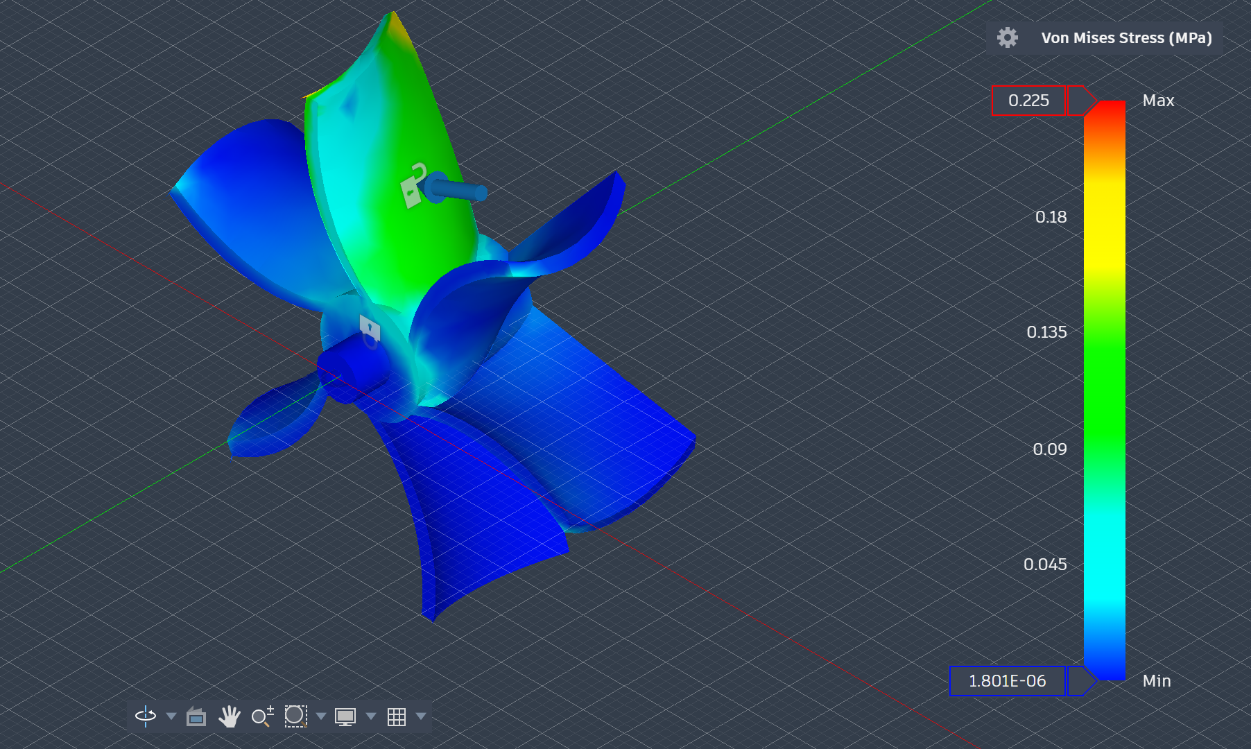
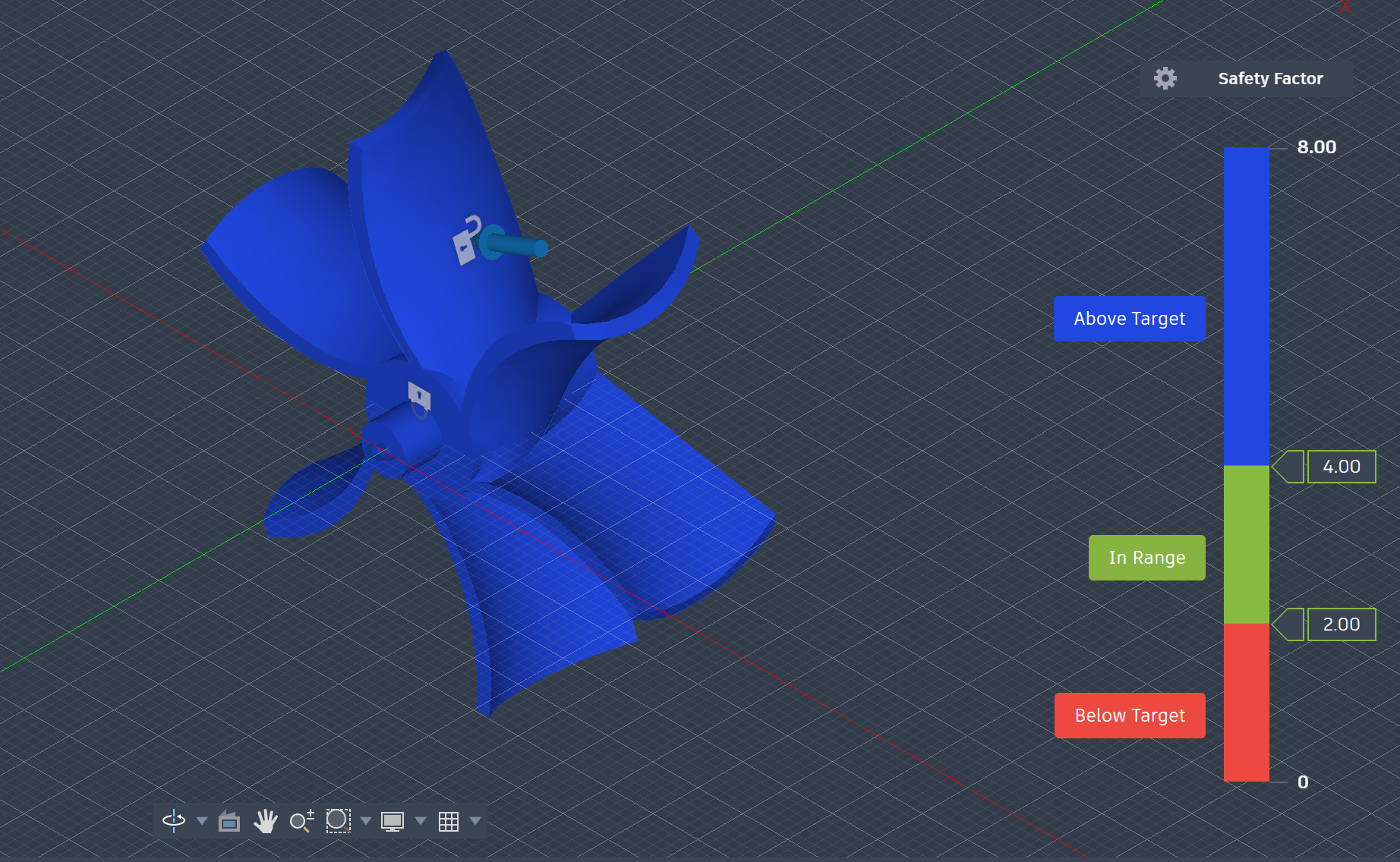
This is the quantitative reason small high-speed turbines need to be taken seriously from a materials/failure standpoint, even though they look like harmless toys, it's also the direct engineering explanation for why a full stress analysis in software like Fusion 360 is worth doing before spinning any homemade rotor up to real RPM.
Limitations & Next Steps
- No energy storage: the current build generates raw AC/DC ripple from the hobby motor but has no rectifier/regulator/battery stage to actually charge a phone.
- Plastic hosing should be replaced with brass or metal-braided hose rated for steam temperature and pressure.
- A rectifier + boost converter + small battery (with protection circuitry) would be the next step toward an actually "functional" charger or way to use the energy.
Supplies
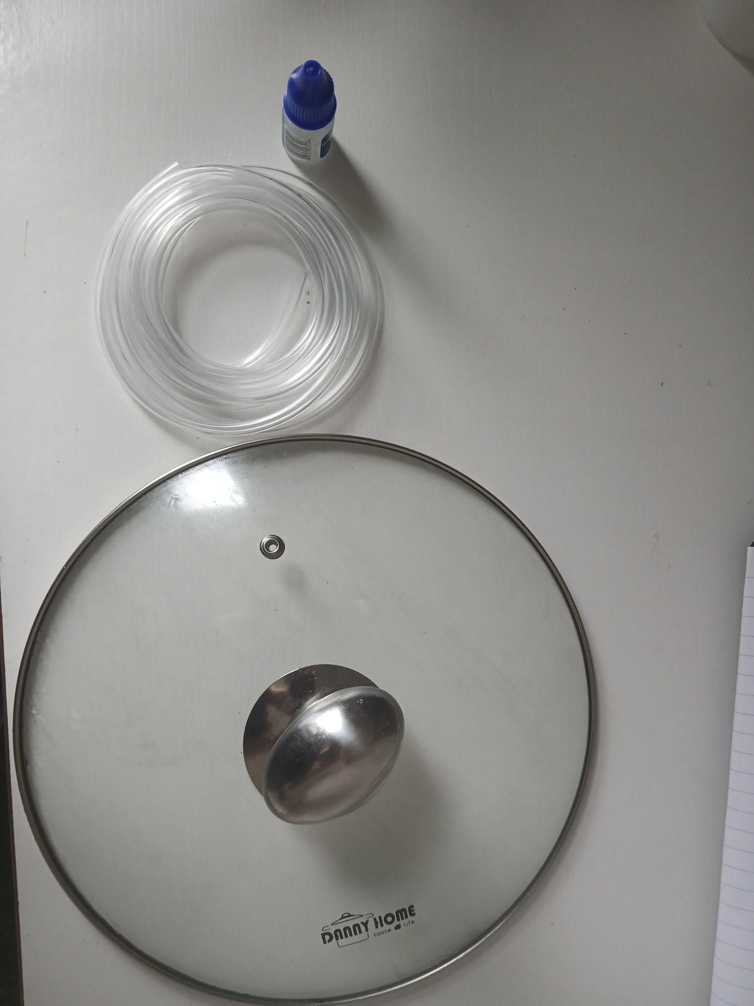
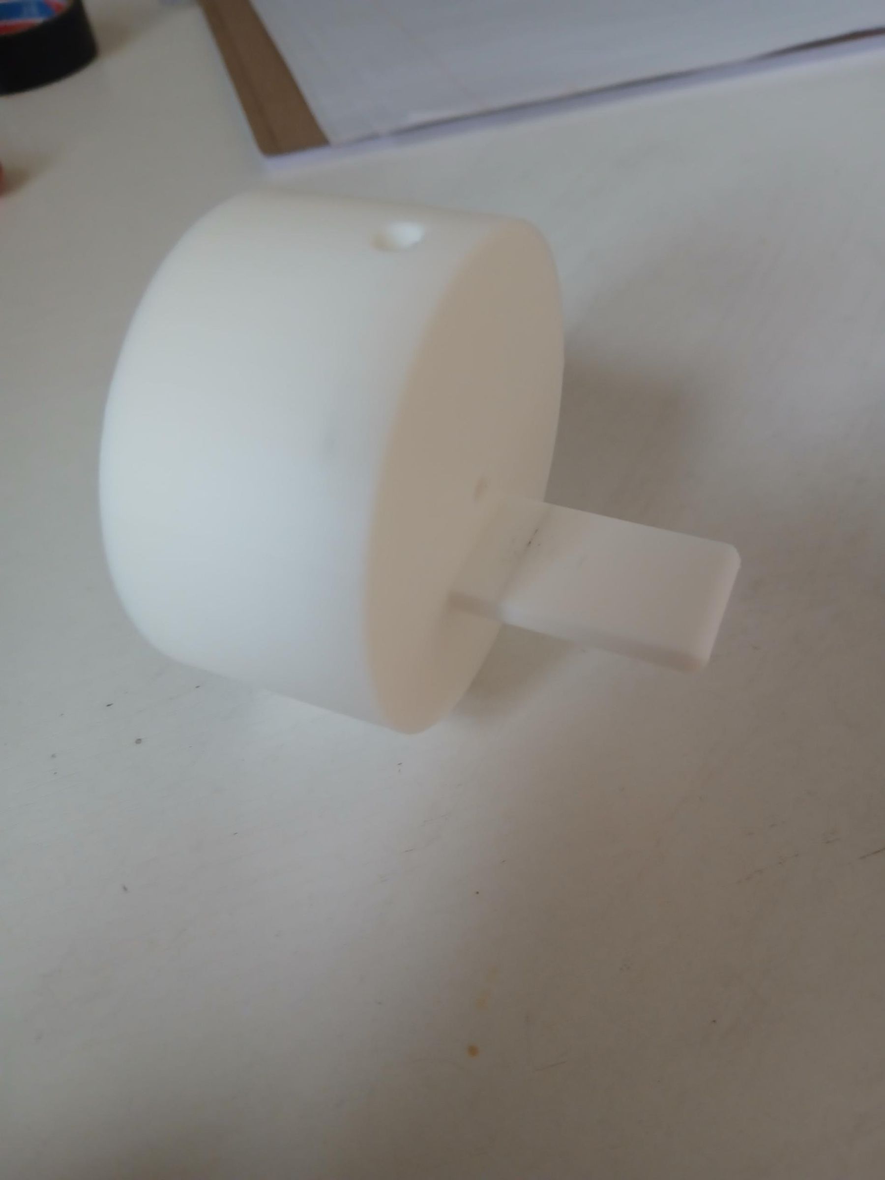
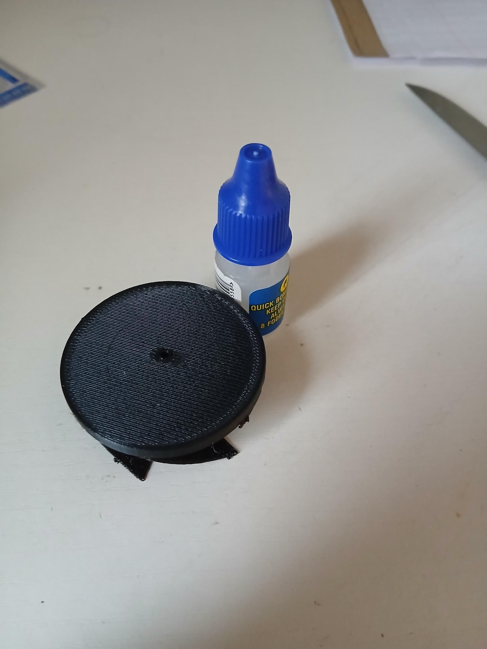
- 3D printer for the turbine and housing. This could be made another way but 3D printing is easiest
- pressure vessule (I'm using a pot lid but a hydroflask or other metal container would work)
- 5mm tubing (prefferably metal but I'm using plastic)
- Type 130 DC motor (Common in scrap electronics but can be bought on amazon)
- Superglue (Amazon)
- Insulation tape (Amazon)
- 3D printed turbine (version 1 or 2, version 2 is more effective)
- 3D printed Housing
- 3D printed Lid
- If necessary a printed adapter for the pressure vessel
Attatching the Motor
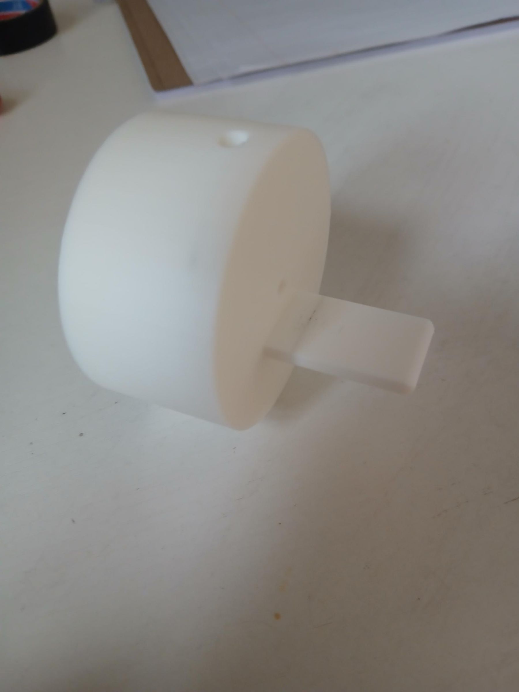
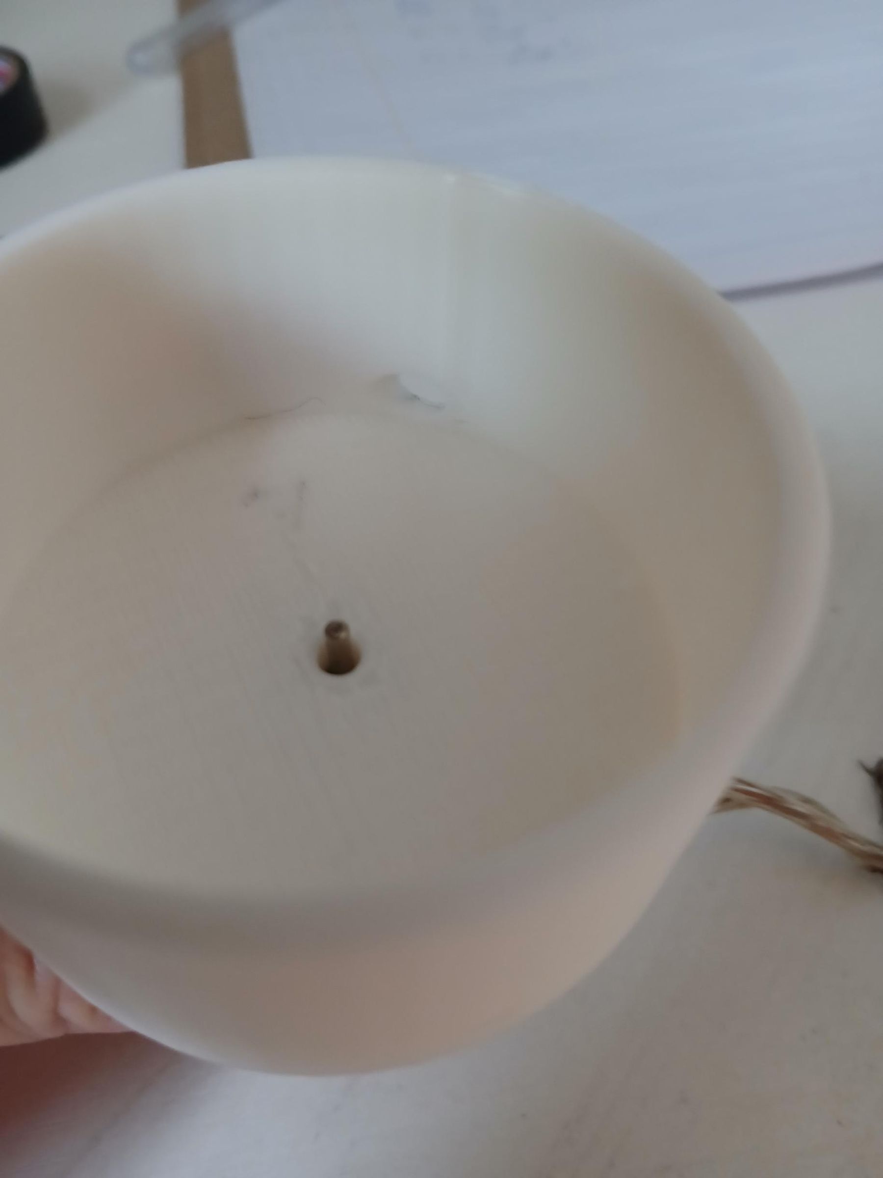
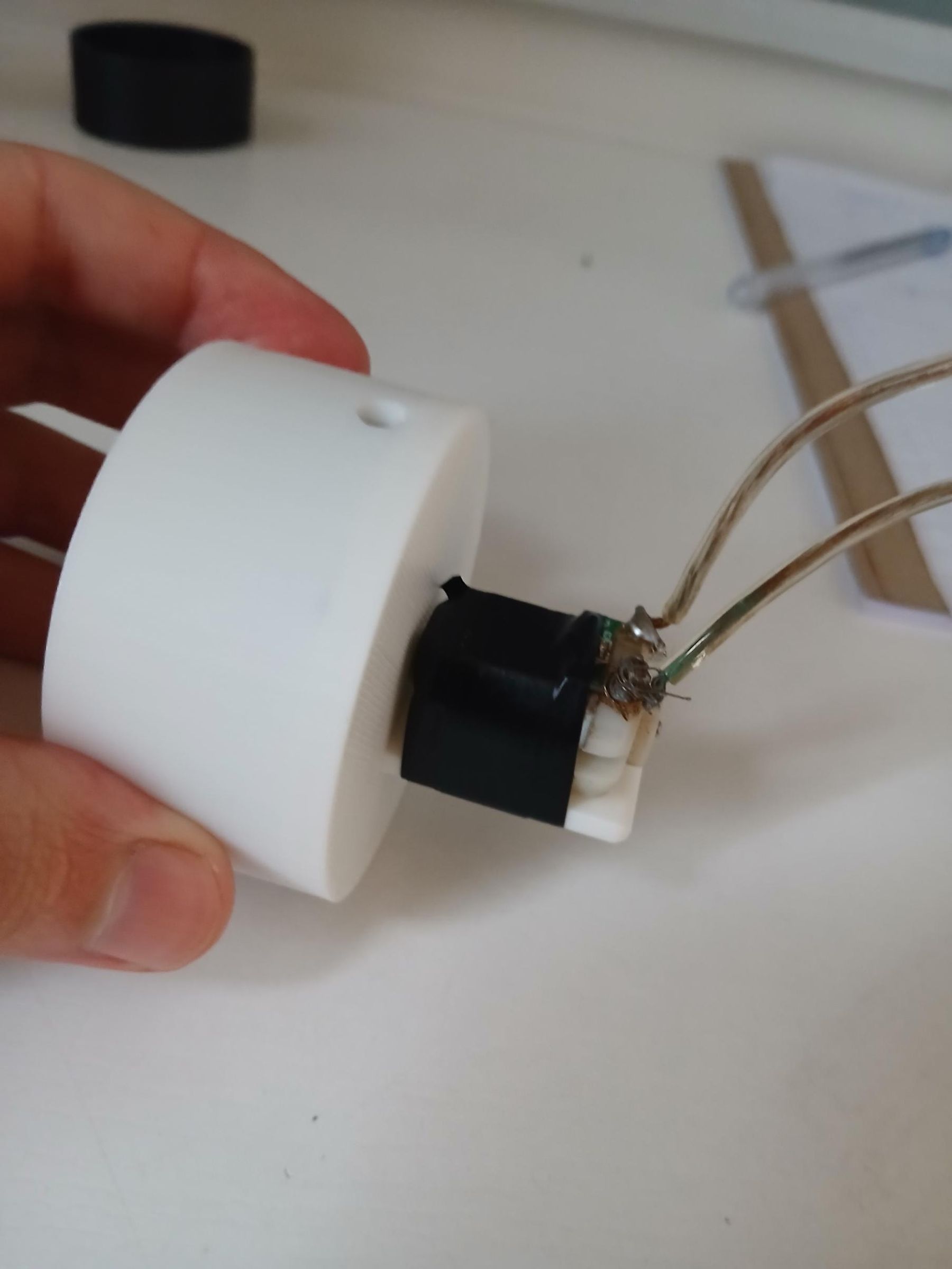
- Place a motor on the ridge of the houseing
- Ensure the shaft comes out a few milimeters on the otherside to ensure a surface for the turbine to mount to
- Using tape or superglue fasten the motor to the ridge
Attatching the Turbine
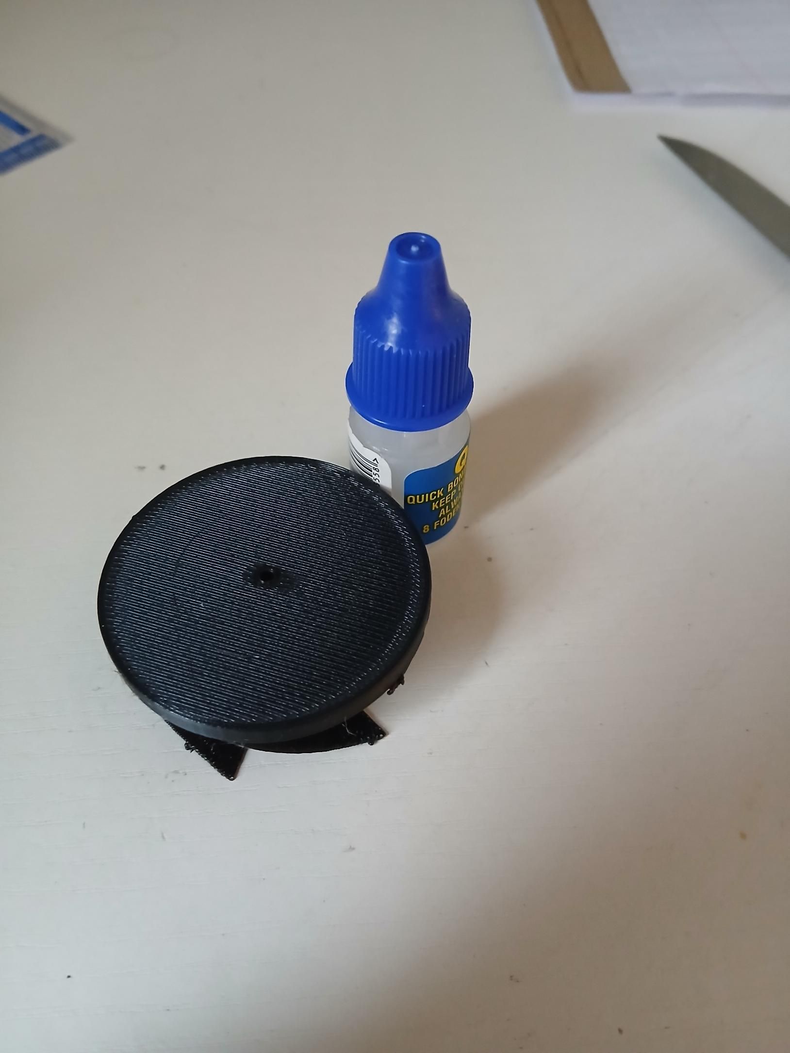
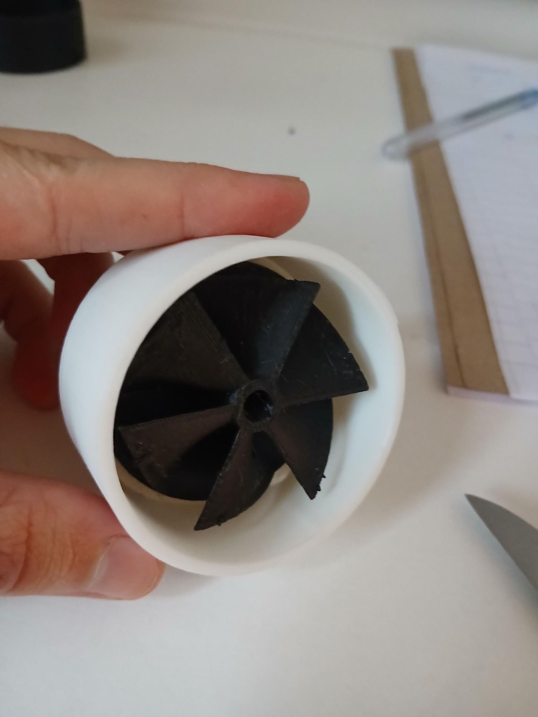
- Test fit the turbine
- If the turbine does not fit on the the rotor easily enough use a drill of heated metal to widen the hole slightly
- Place a drop of superglue on the turbines hole and slide it over the shaft
- Ensure the turbine is centered on the shaft and does not touch the sides of the housing
Attatch the Lid
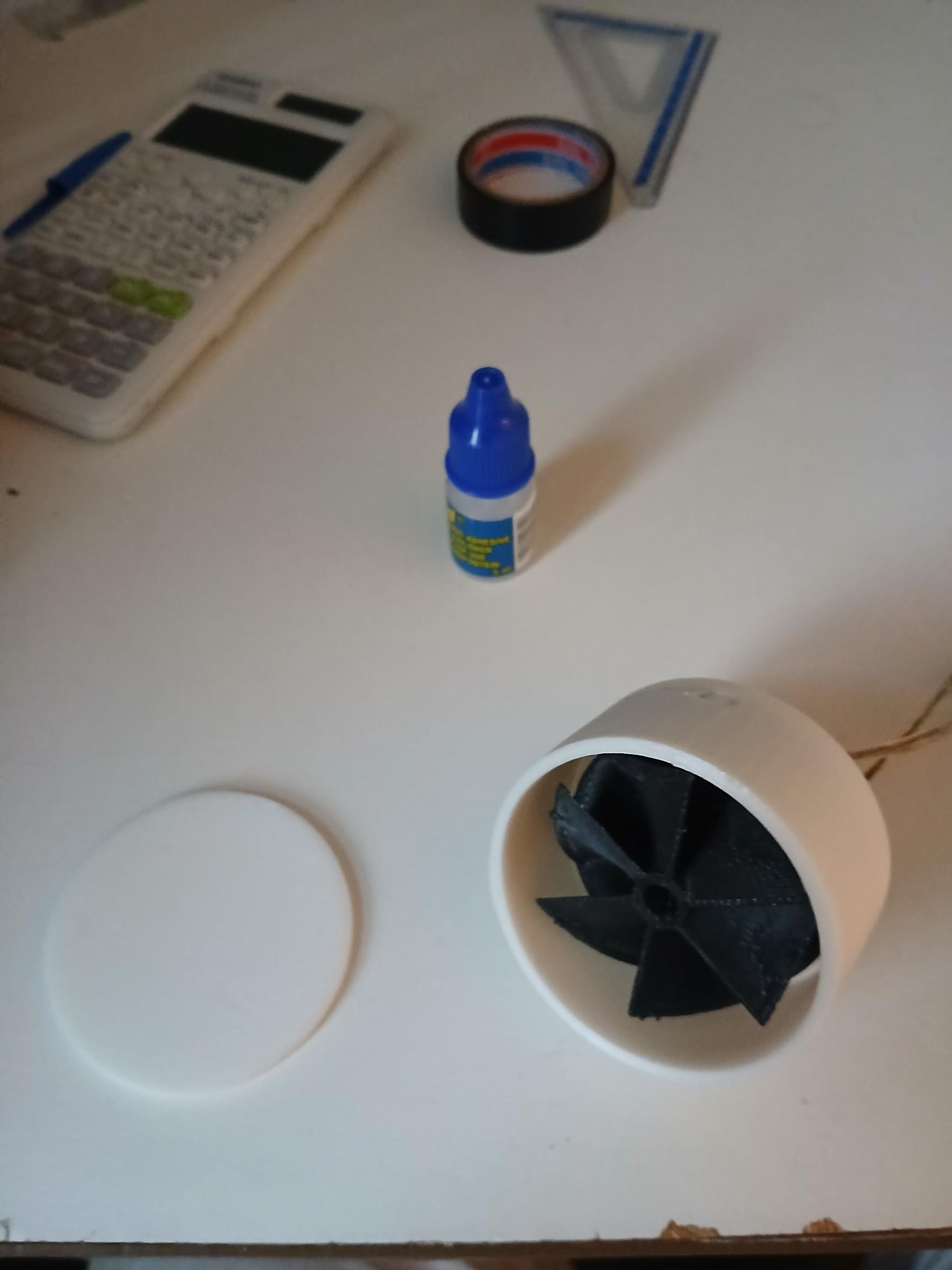
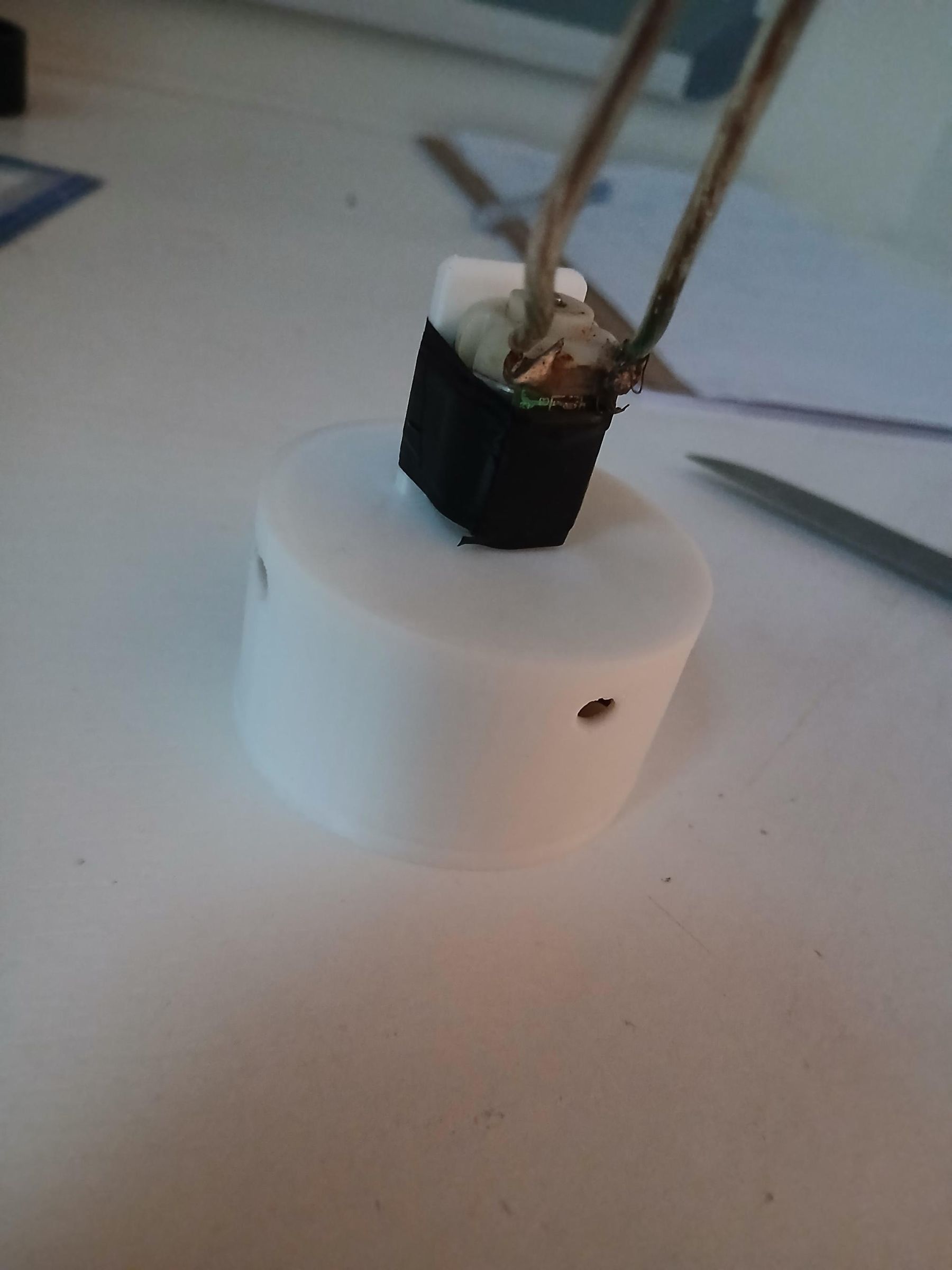
- Using either superglue or heated wire as a pin fasten the lid onto the housing
- Ensure the lid is properly alligned
- Be mindful that glue does not end up in places that could lock the turbine
The Pressure Vessel
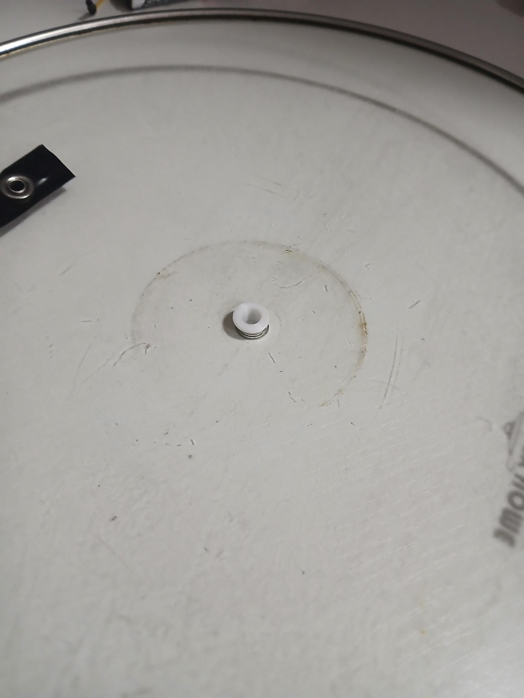
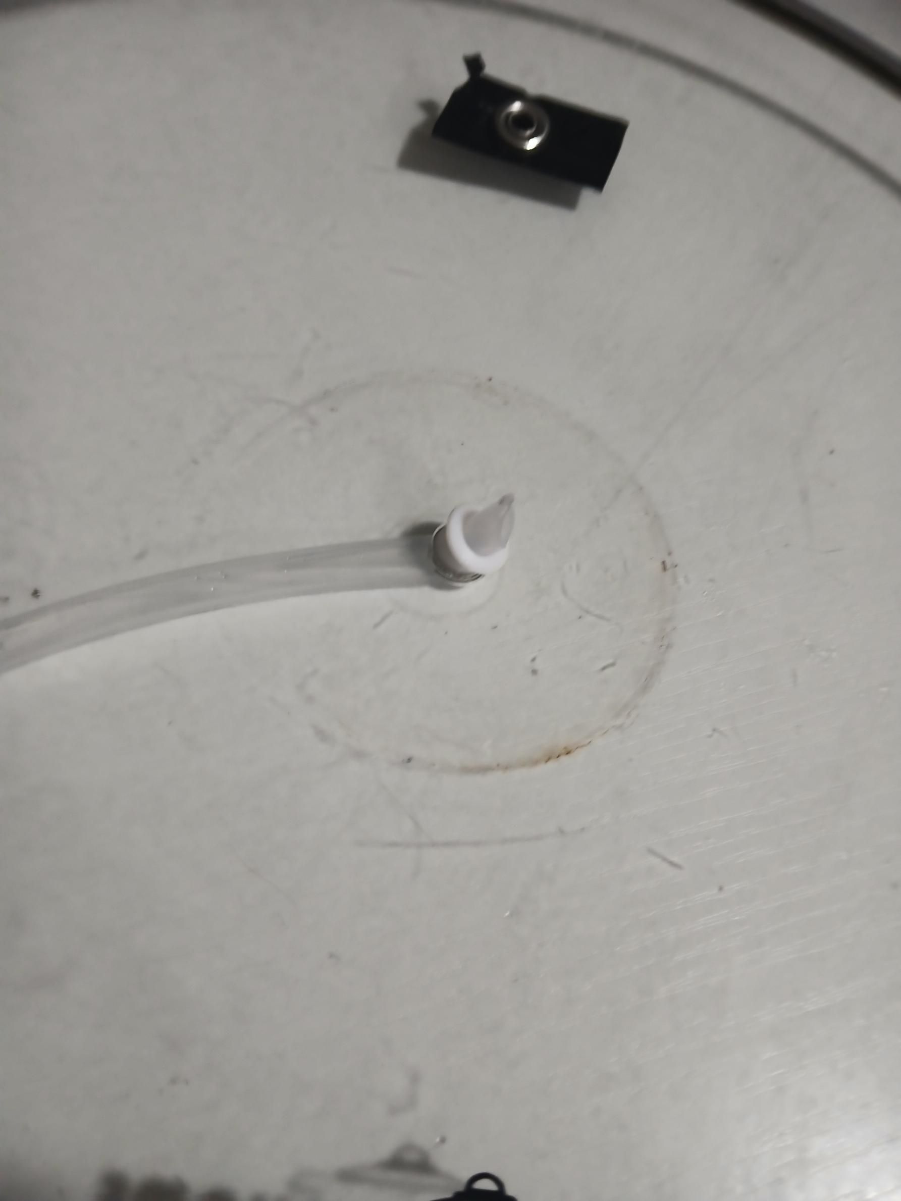
- I am using a pot but a hydroflask or some other kind of metal, water and pressure holding container will work
- Ensure you add a pressure relief. My pot has a small secondary hole to ensure exess pressure is released preventing dangerous pressure build up.
- Make a 5mm hole on the upper portion of the container (I took off the handle of the pot lid)
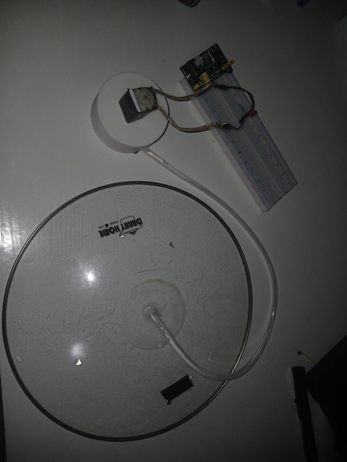
- Using superglue attatch some soft of tubing to the container (A metal tube is ideal but I'm using 5mm air tube) this could also be done with tape to preserve the vessel but it is less secure. I made a 3D printed adapter for the pot.
- Be mindful that a longer tube creates higher energy losses and will slow down the turbine
Assembly
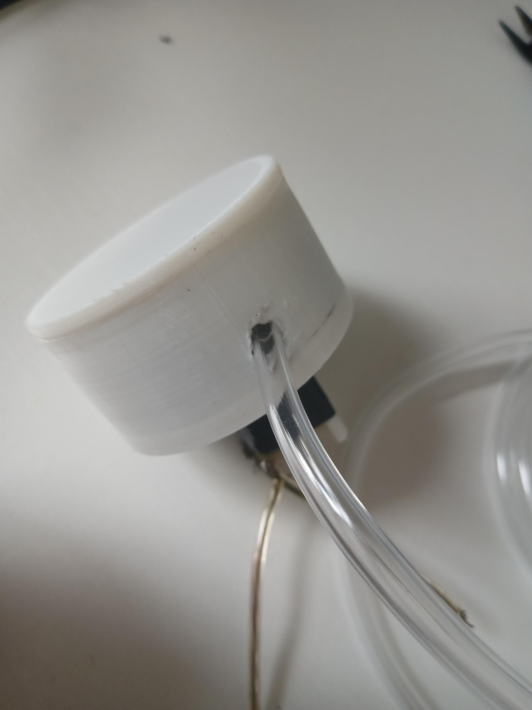
- Place the other side of the tube into the inlet of the houseing (The one that points towards the turbine bucket)
- Superglue the tube in place
Putting It to Work
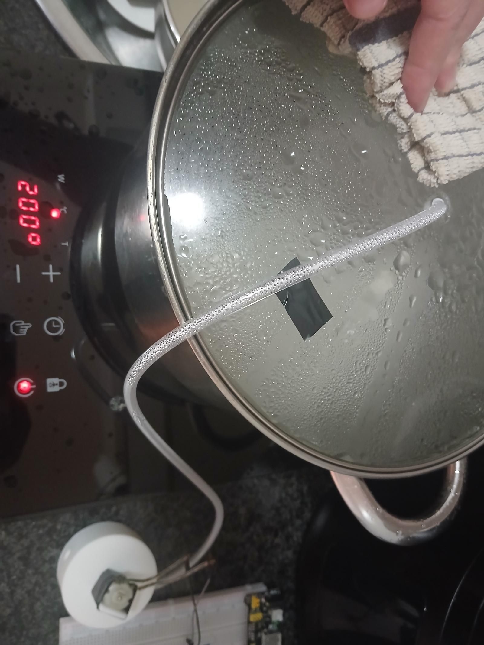
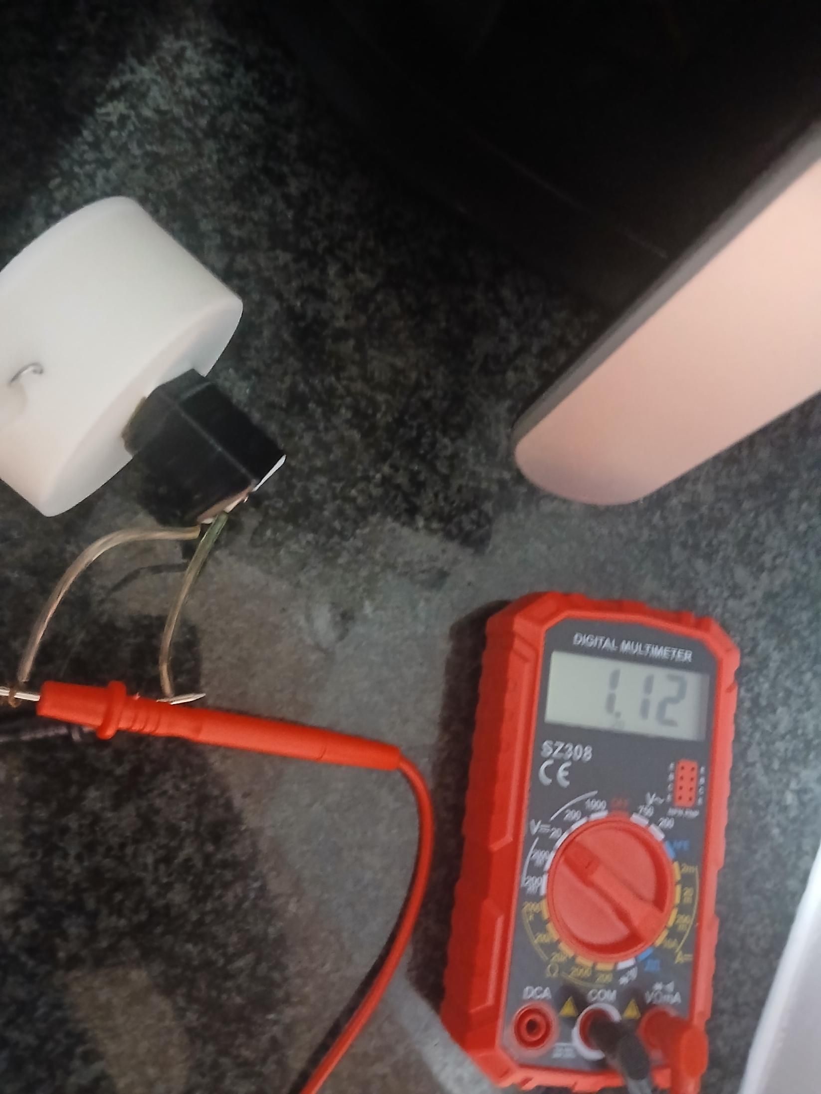
- Connect the motor to whatever you intend to power (Battery charging circuit | LED)
- Place the pressure vessel above heat source (fire or other)
- Ensure you are a safe distance away and allow the water to heat to it's boiling point
- Steam will turn the turbine and generate electricity
Higher steam pressure will speed up the turbine and generate higher voltage
I got a peak of 2v when water reached about 130 degrees before the pipe melted
This was enough to slightly flicker the LED
In further iterations I would use larger brass pipe to allow more steam flow. A nozzel at the end to concentrate the steam and a larger DC motor which requires lower RPM to generate usable voltage.