Potentiometer Arduino LED
by Charlotte-Coding16 in Circuits > Arduino
153 Views, 0 Favorites, 0 Comments
Potentiometer Arduino LED

Legal Disclaimer* This is a high school Mech 1 assignment for the current teacher Mr. Sweet. Should anything happen, he is liable for all damages from this Instructables. His contact is esweet@egusd.net.
Supplies


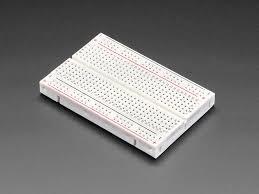
Bread Bored
LED
6 Wires
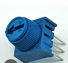
Potentiometer
Arduino
Computer
Wire that connects Arduino to Computer
Downloads
Connect Power Wires to Arduino

Take two wire for the negative and positive of the Breadboard. Attach negative wire to the Arduino GND. Then attach the positive wire to 5V.
Then Connect Power to Potentiometer


Attach a new wire to A0, then place in the middle row of the Potentiometer on your bread bored.
Connect Potentiometer to Negative and Positive

Using the other two rows of the potentiometers, put in same colum as the wires for Positive and Negative on the breadboard.
Take Last Wire to Arduino 13

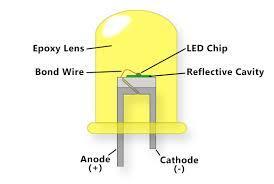

Put through a resistor, then LED. Have the resistor connect to the negative part of bread board.
Code

void setup() {
// put your setup code here, to run once:
int ledPin = 13;
pinMode(ledPin, OUTPUT);
}
int potPin = A0;
void loop() {
// put your main code here, to run repeatedly:
int ledPin = 13;
digitalWrite(ledPin, HIGH);
delay(analogRead(potPin));
digitalWrite(ledPin, LOW);
delay(analogRead(potPin));
}