Power Over Ethernet (PoE) Injector and Splitter (or How to Build a 40ft USB Extension Cord)
by jeff.cartwright.562 in Circuits > Raspberry Pi
8867 Views, 44 Favorites, 0 Comments
Power Over Ethernet (PoE) Injector and Splitter (or How to Build a 40ft USB Extension Cord)

Build a power-over-ethernet splitter and injector for $7.50.
I am thinking about building a Raspberry Pi based "intercom" system. An intercom system is so 70's. So, mine would include home automation control, internet radio, streaming media, TV and intercom functionality. Each room would have its own intercom unit.
I don't want power wires running on the outside of the wall, and putting outlets and junctions boxes on the inside of the wall violates building codes. So, I thought powering the raspberry pi over ethernet might be a perfect solution.
The first decision is make versus buy.
Off-the-Shelf PoE injector solution
A Power over Ethernet (POE) injector and splitter cost about $30 to $60. I have 15 places where I might potentially want an intercom unit. I counted every potential location, such as, garage, portable unit for outside, full bathrooms (2 - bathroom and toilet room), bedrooms, living areas, kitchen. So, for 15 places using off-the-shelf PoE splitter/injector pairs at $30 would come to about $450.
Switch with PoE
Another way to do PoE is to use a switch with built in PoE. Most PoE switches don't have all ports supporting PoE. As an example, an 8-port switch may have only 4 PoE ports. PoE switches are unjustifiably more expensive than a non-PoE switch. An 8 port switch without PoE is about $30. Whereas, an 8-port switch with 4 PoE ports is about $110. I would need 4 switches to get 16 PoE ports, or ~$440.
Coupler-based PoE
So, the approach in this instructable is a low cost, DIY PoE injector and splitter (~$7.50 per room).
The internet has many PoE designs.
The basis of this instructable is Power Over Ethernet (PoE) Adapter by eLab. Read this instructable first. I will give best effort not to repeat the contents of eLab's instructable. eLab's instructable is excellent.
eLab's solution uses:
- Surface mount ethernet jack (2 x 2 1/8 x 7/8 in) plus female ethernet jack about $6 x 2 = $12
- Barrel pin power supply and output $4
The changes from eLab's solution are:
- 2x Ethernet coupler (1.5 x 5/8 x 7/8 in) $2.10
- Male USB and micro-b USB for power about $4.69
Advantages:
- Coupler has smaller form factor than surface mount housing
- Coupler doesn't require mounting and can be used in-line
- Costs for eLab's solution were determined by looking up parts on Amazon. No effort was made to find lowest cost parts. So, cost is arguably less for a coupler-based solution over a surface mount solution.
- USB & micro-USB is better for Raspberry Pi that barrel pin power adapter
Limitations of both:
- Not PoE 802.3 standards compliant - may destroy your equipment - use with caution
- Can do 10 or 100Mb but cannot do Gb Ethernet
- 5v supply can go about 39ft with 0.5v loss
Gather Parts
Get parts and tools (prices in USD):
- 2x Ethernet couplers, Amazon $1.05
- Micro USB to USB cable 3ft from Amazon $4.69
- 5.2V 2.1A USB Power Adapter from Amazon $5.99
- Micro USB Type AB Receptacle Mouser $0.81
Things I had a round the house:
- Strong sharp knife with flat blade
- Exacto knife
- Needle nose pliers
- Drill and 9/64 steel drill bit
- 2x blue zip ties
- Volt meter
- Electrical tape
- Small, sharp scissors
- Soldering iron and solder
Notes:
- The current used by the powered device is a key parameter in determining the distance. According to raspberry pi wikipedia, the max current drawn for a pi is 0.8Amp. I used 1Amp.
- Text enclosed in spades, such as, ♣replace-this♣, should be replaced with an actual value. Of course, remove the spades.
Downloads
Coupler
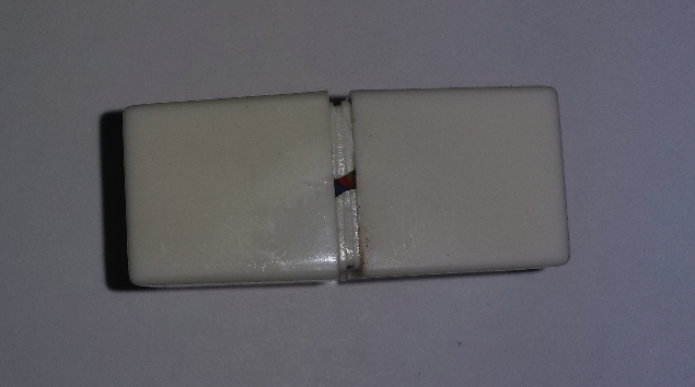


One coupler will be used for the Power over Ethernet injector, and the other will be used for the power over ethernet splitter.
Using a flat sharp, strong knife, slide the knife into the crack on the thin side of the coupler, and then twist the knife gently prying open the coupler. Pry open the other coupler.
- The wires in the coupler are long, and then twisted so they all fit inside. Untwisting the coupler wires makes the work easier.
Using a 9/64 steel drill bit, slowly drill a hole from the inside of the coupler to the front of one side of one coupler. I chose a spot where there was already a bit of an opening to the front, and the drill bit would not touch the coupler's wires. Drill a hole in the other coupler.
- A chose a 9/64 bit because bit's width was close to the USB cable's width. The cord should fit through the hole and be snug with no visible gaps.
- Steel drill bits go through plastic without making an eyesore of a hole.
- After I drilled the holes, the cord didn't want to go in. When pushed in, the outer cable cover bunched up. So, I ran the drill bitt through a couple of times, and cleaned up all rough or sharp spots with an exacto knife.
- When I pushed the cord through the hole, I twisted it a little bit back and forth. Once the cord was far enough through, I used a needle nose pliers to pull the cord the rest of the way.
Use needle nose pliers to cut the USB cord. I cut the micro-USB end of the cord to about 10 inches in length, leaving the USB end at a little over 2 feet.
Using the drilled hole, slide one end of the cord through the front of the coupler. The USB connecter should be outside the coupler.
Strip Wire, Add Strain Relief and Measure

Start with the USB end. Pull enough cord through so it is comfortable to work with.
After the cord is pulled through the hole do the following:
- Strip ~1 inch of the outer cover on the USB wire.
- Remove all of the insulation - copper wire and aluminum sheathing.
- Cut away the fiber, leaving a red, green, white and black wire.Strip ~1/4 inch from each wire.
If the cable is made according to standards, then the red is 5v and the black is ground.
Hook up a meter and test to make sure this is correct. In the image, the meter is set to 10v DC.
- Red is Vcc, positive or 5v
- Black is Ground, negative
- Snip off the green and white wires
Inside the coupler, on the USB cord, close to where the outer cover is stripped away add a zip tie (see image). Pull the zip tie very tight. This will act as a strain relief.
Pull the USB cord back so the zip tie is touching the coupler.
Repeat the above for the coupler with the micro-USB connector. Skip the meter step. Keep the same color wires on the micro-USB.
Attach Coupler Wires to USB Wires
The wires in CAT5e and and CAT6 are twisted pairs. By using both wires, the voltage will be transmitted farther with less drop. If a single wire is used than the transmission distance is ~19 ft. If both wires are used, then the transmission distance is ~40 ft.
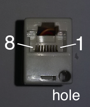
An ethernet coupler was not intended to be taken apart. So, the wires on the inside of a coupler may not match the wire color standards used in CAT5e or CAT6 cables.
- Pins 4, 5, 7, 8 are not used in CAT5e
- Use blue pair (4 & 5) as positive or 5v
- Use brown pair (7 & 8) as negative or Ground
The USB cable comes in through one side of the coupler.
- Cut the wires connected to pins 4, 5, 7, 8 on the side where the USB cable enters - leave the other side connected
- Cut as close as possible, but all that is needed is enough to work with
- Write down the color and pin #. In my case, the pins and colors are:
- 4 = red
- 5 = green
- 7 = white
- 8 = brown
- Strip 1/4 inch off the coupler wires
Twist and solder together:
- coupler red and green wires to USB cord red wire
- coupler white and brown wires to USB cord black wire
Wrap the soldered ends in a small piece of electrical tape (cut a small piece - don't rip).
Twist the wires and push the coupler back together.
Repeat the above for the other coupler
You are done!
Downloads
Appendix: References
Basis for Instructable: https://www.instructables.com/id/Power-Over-Ethern...
Voltage Drop Calculator: http://www.active-vision.com/max-distance-voltage...
Wikipedia showing mAmp drawn by all models of Raspberry Pi https://en.wikipedia.org/wiki/Raspberry_Pi
Wikipedia PoE https://en.wikipedia.org/wiki/Power_over_Ethernet...
USB: https://en.wikipedia.org/wiki/USB#Mini_and_Micro_...
Raspberry Pi stack exchange http://raspberrypi.stackexchange.com/questions/71...
Pi Supply - Pi PoE Hat https://www.pi-supply.com/product/pi-poe-switch-h...
Raspberry Pi org https://www.raspberrypi.org/forums/viewtopic.php?...
PoE Kit http://www.eidusa.com/Electronics_Kits_PoE_inject...
Appendix: Updates
12MAY2016:
- minor text modifications, added some new references
01JUN2016:
- added measurements to Appendix
02JUN2016
- redid Appendix measurements and added second power adapter and more explanation
Appendix: Troubleshooting
Test
Connect USB power supply to USB. Run Cat5e or CAT6 cable between the injector and the splitter. Plug the micro USB into a device that needs power and see if it works.
Appendix: Measurements

For the measurements, I used a
- 5.3V USB plug and a fast charging 10 port USB plug
- two jumper cables stripped at one end
- A low-cost voltmeter
- USB to micro USB cable
- 10ft, 25ft and 50ft CAT5e ethernet cables
- splitter and injector made in this instructable
- Raspberry Pi 2.
One end of each jumper cable was stripped, about 1/2 inch. Jumper cables were attached to 5V and Ground pins (physical pins 2 and 6) on a Raspberry Pi 2. Nothing was plugged into the Raspberry Pi's USB ports. To make a better connection (stable), the stripped end of the jumper cables were wrapped around a voltmeter's probes.
For 5.2V plug:
Cat5e Cable length : voltage
- 0 feet : 5.2V
- 10 feet : 5.0V
- 25 feet : 4.8V
- 50 feet : 4.4V
At 50ft, the measurements fluctuated between 4.7V and 4.4V, and at 25ft between 4.9V and 4.8V.
For fast charge USB plug with current and voltage control (spec'd at 5V but supplies more):
Cat5e Cable length : voltage
- 0 feet : 5.5V
- 10 feet : 5.2V
- 25 feet : 5.1V
- 50 feet : 4.7V
On a Raspberry Pi, do not supply too much current or voltage, or the unit could be damaged (~5.25V), and do not supply too little or the Raspberry Pi may not work properly (~4.75V).
According to http://nordicgroup.us/rpi/power/:
“Raspberry Pi starts operating erratically below 4.75V”
[You must have a power supply that outputs] “2.4A at 5.2V (12 watts). The extra 0.2V mitigates the effect of the voltage drops in the cable and on the Raspberry Pi board.”