Powering a 90s Cassette Player With a Lithium Polymer Cell
by normalinstances in Circuits > Electronics
66 Views, 0 Favorites, 0 Comments
Powering a 90s Cassette Player With a Lithium Polymer Cell
.jpeg)
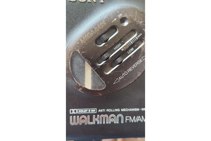
A few months ago, I had bought a few AA NiMh batteries to power my aging Sony Walkman WM-FX36 cassette player. However, due to my haphazardness in leaving them in a charger meant for NiCd batteries for much too long, they all unfortunately met their demise.
In my frustration, I decided to think about alternative ways to power this old musical brick.
I thought about a cheap 3V wall adapter that could plug into the player's DC input, which although did not need to charge, completely eliminated the portability of a portable cassette player.
So, I decided to use batteries again. This time, I chose a different chemistry, lithium polymer. I had a few replaceable phone batteries I extracted from old Nokias and I wanted to try using them instead of leaving them to rot inside my parts bin.
Then, with a couple of old parts, some new ones, and a hot soldering iron, I decided to work on an extremely minimal setup, which can turn any 3V cassette player with a 3.5mm DC barrel jack into one that is powered entirely via a lithium polymer battery.
The goal of this project is simply the pursuit of cost efficiency and accessibility of finding these parts, especially as I come from a place where buying parts from overseas is, most of the time, very cost-inefficient. Therefore, this project will not require a 3D printer and it will not require you to fabricate a PCB. Without further a do, let's get into it!
Supplies
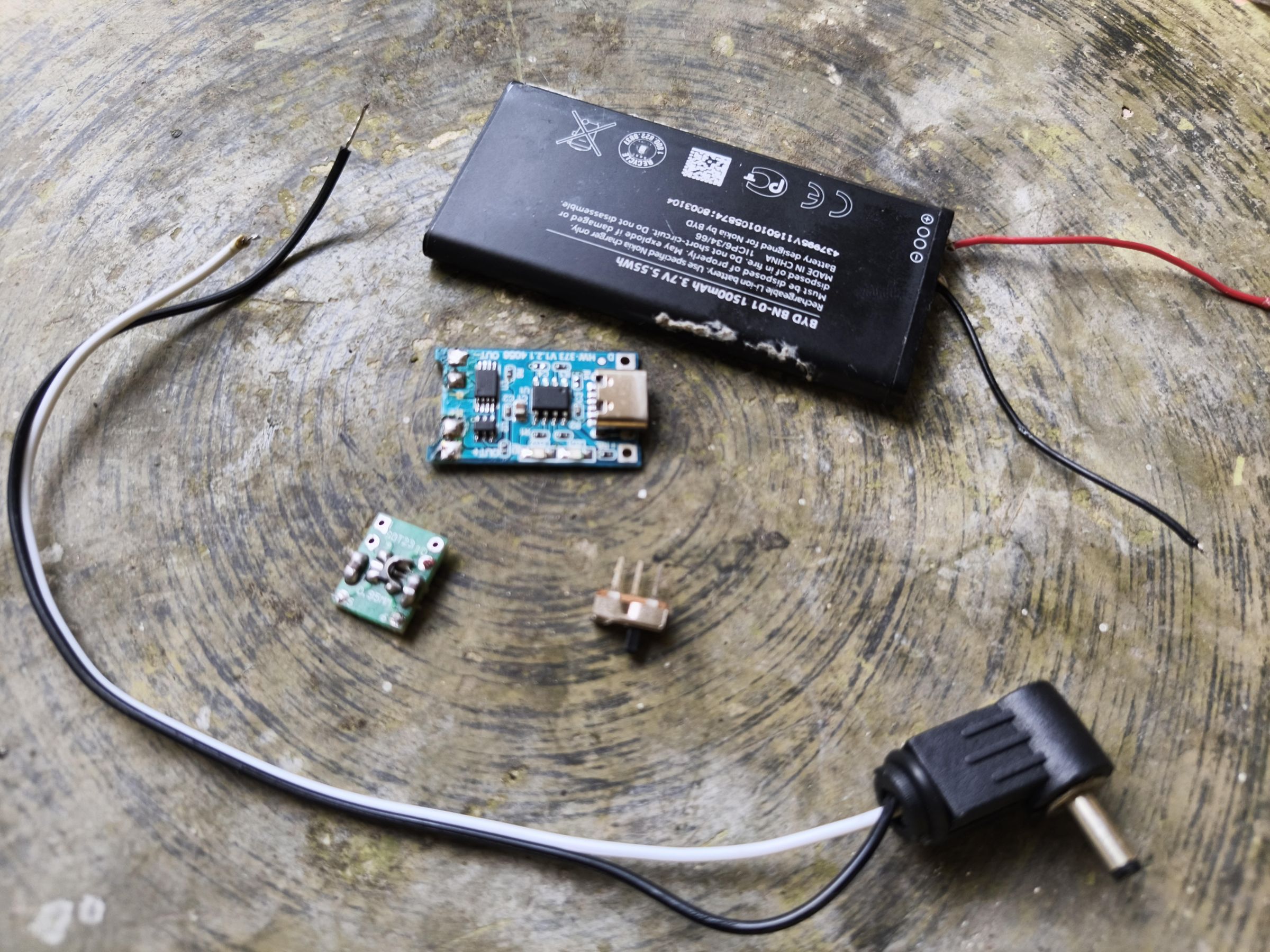
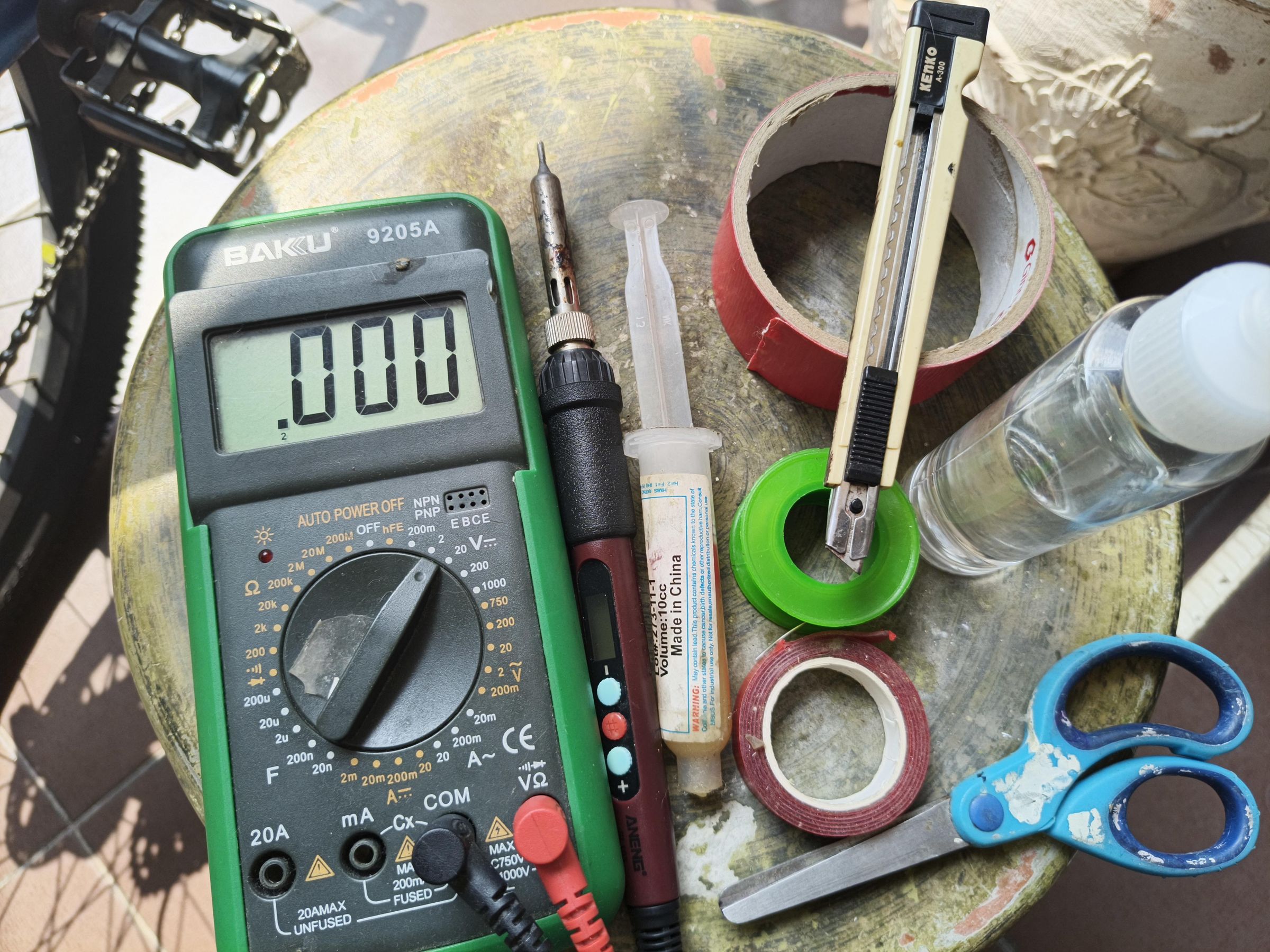
For this project, I used:
- 1x Cassette Player that runs on 3V and has a DC input that uses a 3.5mm jack
- If it doesn't have DC input, you can try soldering the output cables of the LDO module to the battery contacts inside the player.
- 1x Lithium Polymer Battery
- I used an old Nokia phone battery for this (1500mAh), but if you have a lithium polymer cell with an adequate size for your cassette player and built in protection, please use that instead! I am relying on the DW01 chip on the TP4056 board to do the protection here.
- 1x SOT-23 breakout board
- 2x 1uF MLCC 0805 Capacitors
- As seen in the datasheet for the LDO, a 1uF cap on both the input and output is enough! Though 2.2uF for the output might do better.
- 1x WPMtek WL91935S-30
- I had never heard of this LDO before, but a local online store was selling them, and they had lots of it. So I said, "Why not?"
- 1x TP4056 with Protection
- 1x 3.5mm DC barrel jack
- Preferably L-shaped
- (Optional) 1x 3-pin SPDT switch
- Cables of suitable gauge
- I used cables from those rainbow jumper cables, so... 26 AWG?
- Leads from old through-hole components
- I took some from a random resistor's lead clippings I had from a previous project
And for tools:
- A Soldering iron
- A knife and a pair of scissors
- A roll of solder
- A multimeter
- Flux
- 99% Isopropyl
- Clean your boards after soldering!
- Double-sided clear mounting tape
- To keep repair easy and to avoid superglue, mounting tape is a godsend. Just use some floss or string and it'll peel right off with the attached part!
- Cloth tape
- Microsoft Paint (very professional)
- Canva
- Premiere Pro
Assemble the LDO Board (Upper)
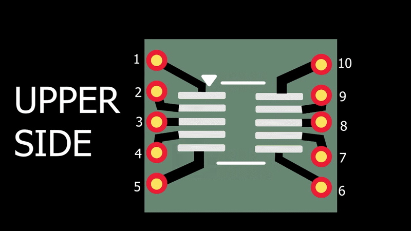
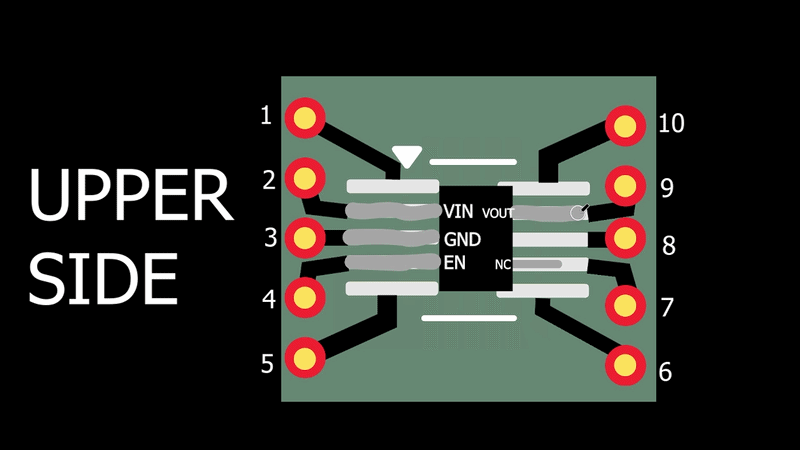
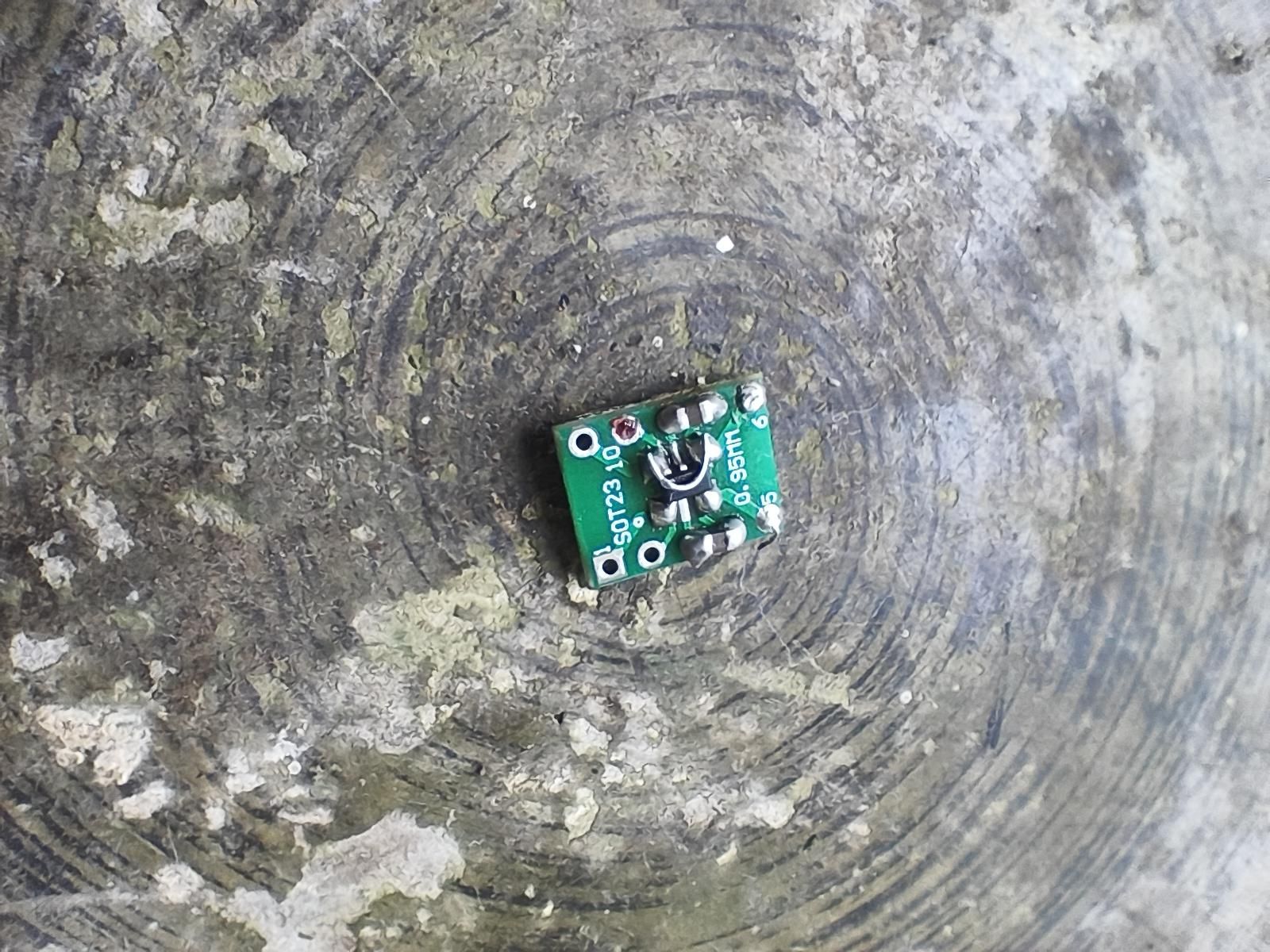
First, solder the LDO on top of the breakout board. Short the free pads on the left and right side of the leftmost with rightmost pins on both sides of the SOT-23-5 LDO in addition to the pads they are already sitting on (this one was a handful to type, I think I might have stroked).
TIP1: Use something like sticky tack between the board and your workspace so that it doesn't go anywhere.
TIP2: It might get hard to distinguish which side has the GND pin and which side does not if you don't have a magnifying glass/microscope once it's on the board. In this case, shine a light on the chip or carefully run a toothpick along the pins. Two bumps mean it's the output side. Three bumps mean it's the input side.
TIP3: RECHECK YOUR CONNECTIONS
Assemble the LDO Board (Jumper #1)
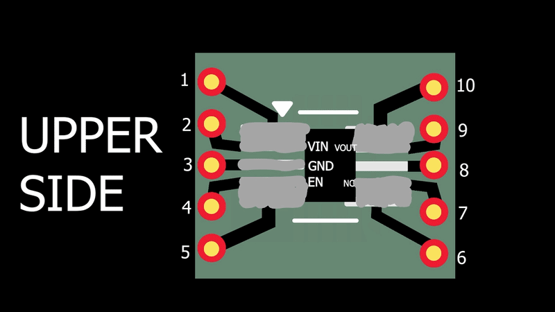
Then, if you have any excess through hole component lead, cut to length, and bend it to a U shape to jump the VIN and EN pins directly (if not, snip away, you monster!).
Finally, solder on the 0805 capacitors between the vias connected to the VIN and GND pin, as well as the one on the other side connected to VOUT and the jumper wire connected to GND.
Assemble the LDO Board (Lower)
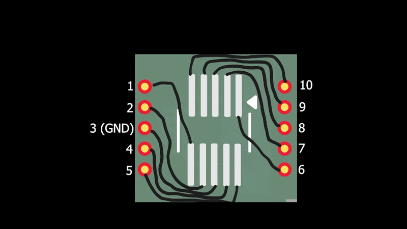
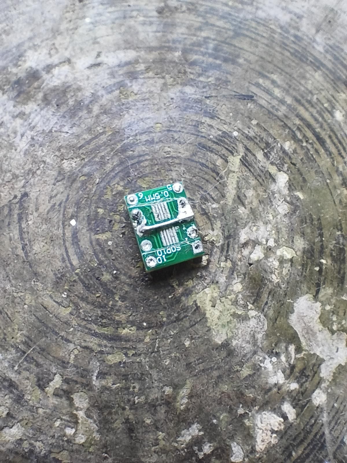
Once the LDO is in place, flip the board over, before sacrificing an through hole component by cutting one of its leads off to length and use it to solder and jump the via connected to the GND pin with the one opposite to it.
In order to prevent the pads of the MSOP10 footprint from shorting with this jumper, get a knife and cut the traces leading out of the pads.
Another way to do this is to just cover up the pads with tape (if you want to live life on the edge).
From now on, we will refer to the breakout module's vias to the pins they are respectfully connected to.
TIP1: Use something like sticky tack between the board and your workspace so that it doesn't go anywhere.
TIP2: It might get hard to distinguish which side has the GND pin and which side does not if you don't have a magnifying glass/microscope once it's on the board. In this case, shine a light on the chip or carefully run a toothpick along the pins. Two bumps mean it's the output side. Three bumps mean it's the input side.
TIP3: RECHECK YOUR CONNECTIONS
Why Use an LDO?
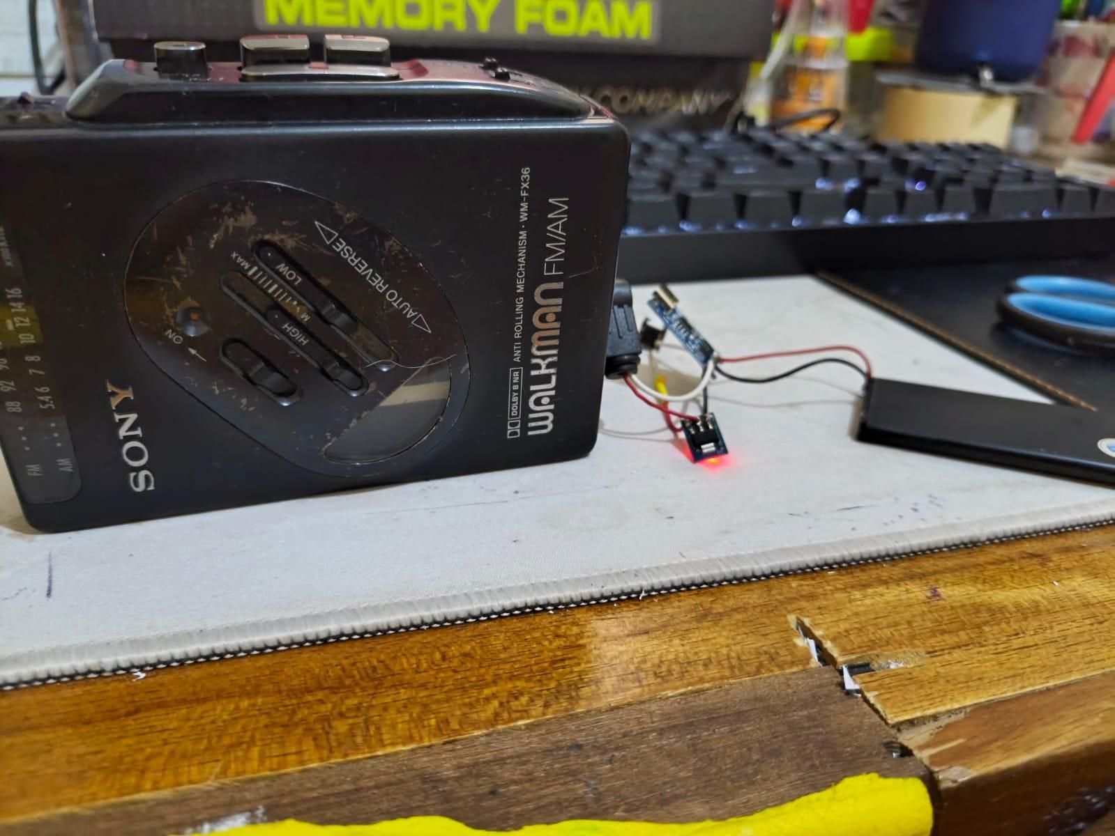
As this is an audio application, I did not bother using buck converters as they might introduce switching noise that could mess with sound quality. In addition LDOs are perfect for stepping down voltages which don't have that big of a gap between them because they dissipate that extra energy into heat instead of the switching-mode shenanigans in a buck converter. In this case, the lithium polymer battery can output at most 4.2V, which needs to be stepped down to 3V. That's a 1.2V difference (it's small).
A consideration I had is why shouldn't I just use an off-the-shelf AMS1117 module?
Well, I have tried replacing the LDO board with the 3.3V version of the AMS1117 (as shown in the pic). It has a very high dropout voltage (1.2V from testing using the current draw from the cassette player). So much so, that it would fall out of regulation at the battery's highest voltage(4.2V-1.1V = 3.1V < 3.3V). In contrast, the WL91935S-30 only has a dropout voltage of 240mV-390mV at 300mA per the datasheet.
Also the AMS1117 ran hot for some reason (maybe because of the inefficiency and high dropout? I am curious, please if anyone knows, reach out via the comments!).
DC Barrel Jack
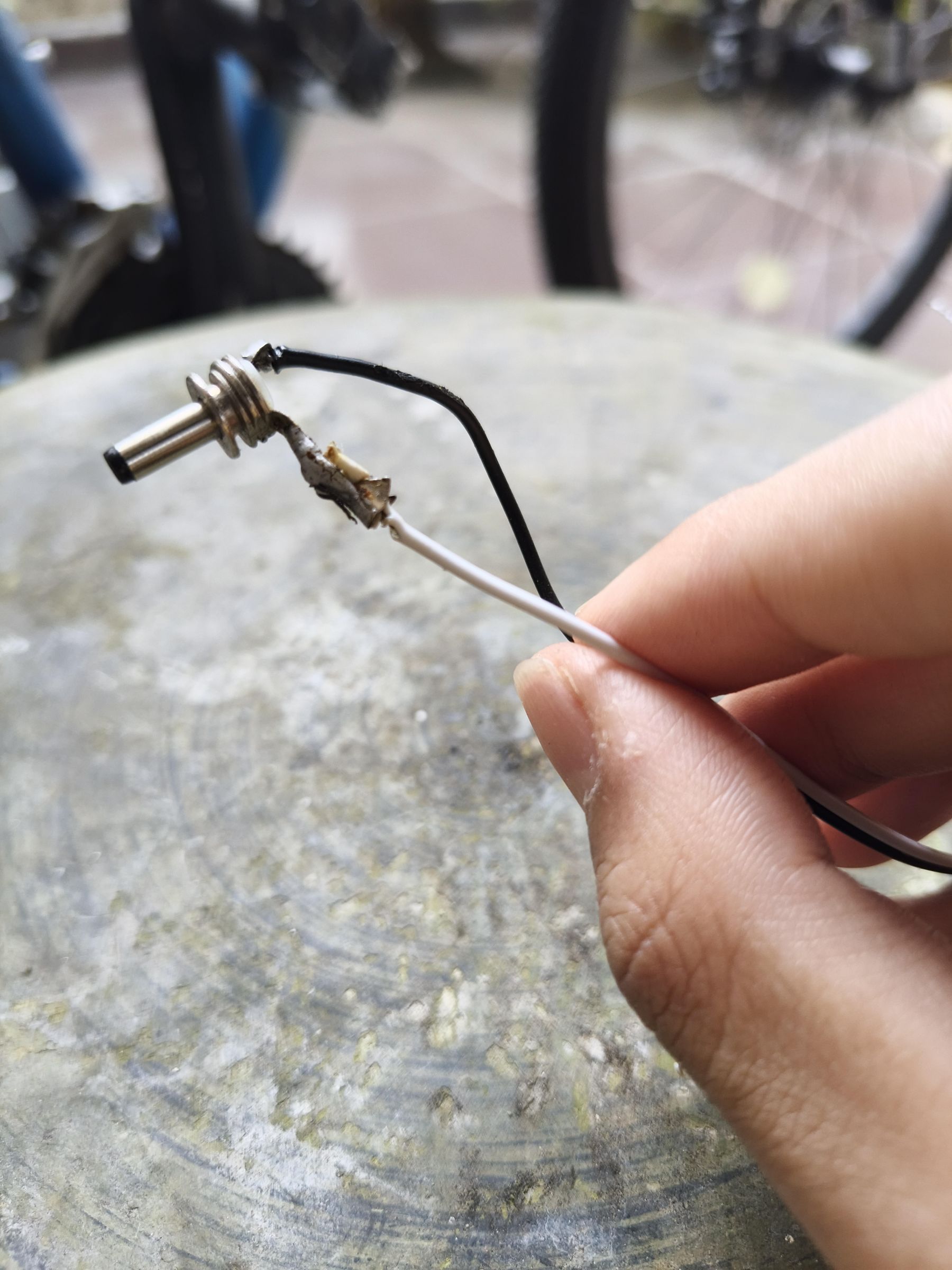
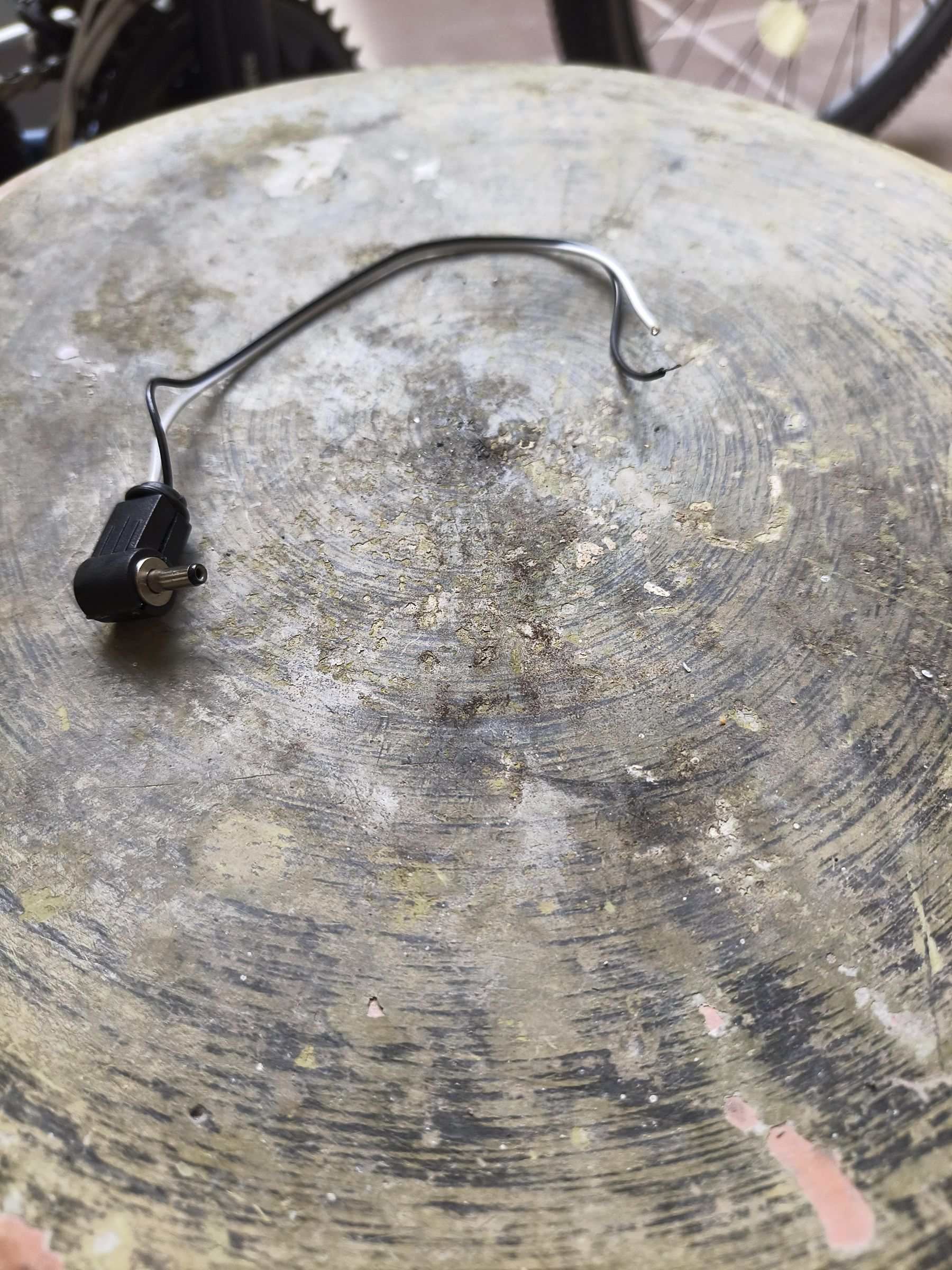
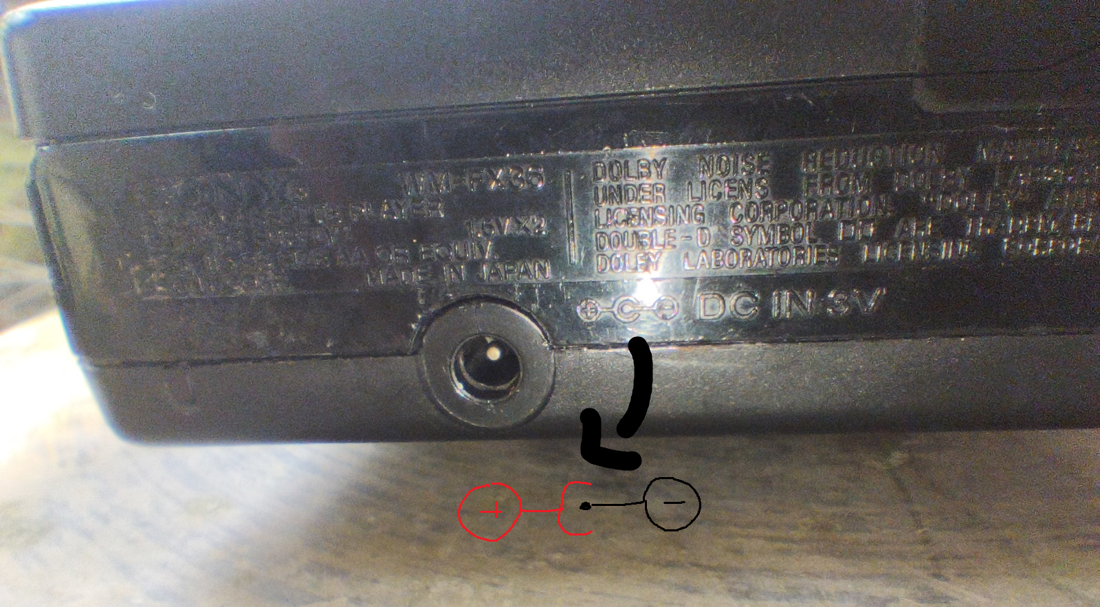
Check out the dc barrel markings near the jack or check your cassette player's repair manual for schematics. If the bigger prong shaped thing has a positive (+) symbol and the smaller dot thing that it's eating has a negative (-) symbol, then solder the sleeve of your DC barrel jack to the cable meant for VOUT, and the tip to the cable meant for ground and vice versa.
Solder Wires on Your Battery
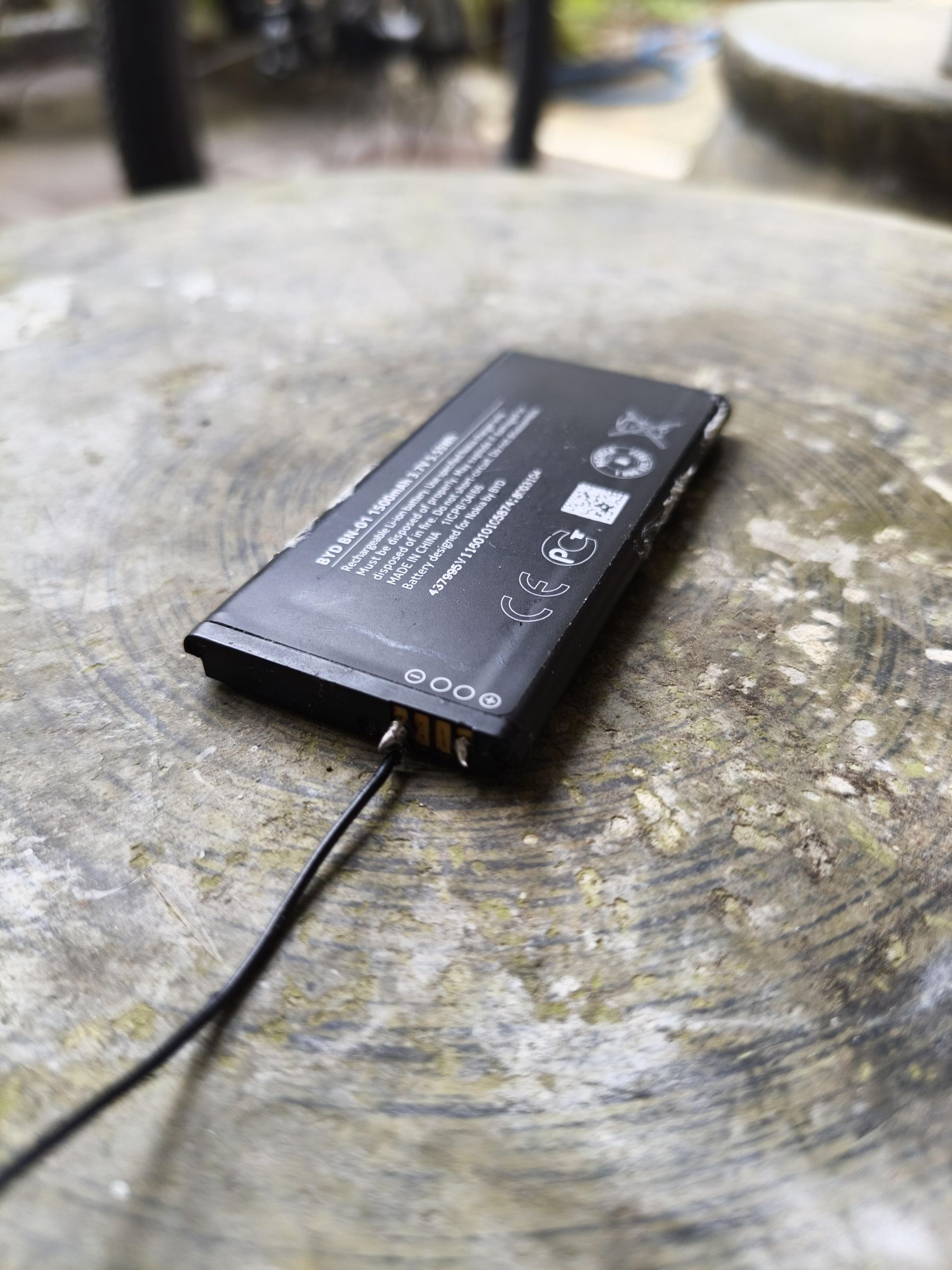
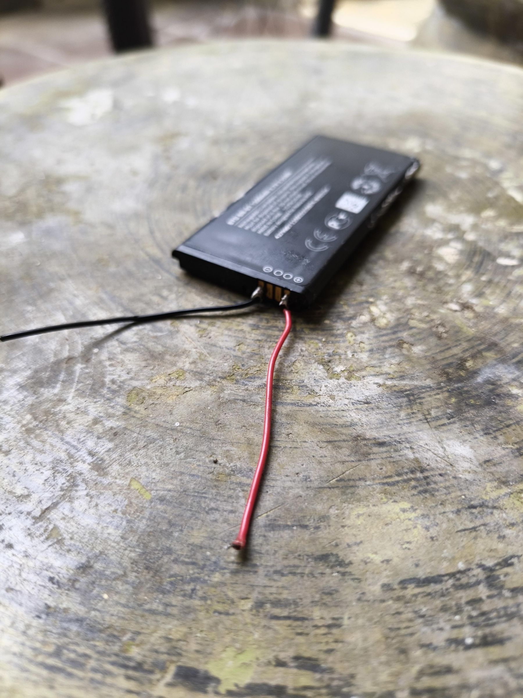
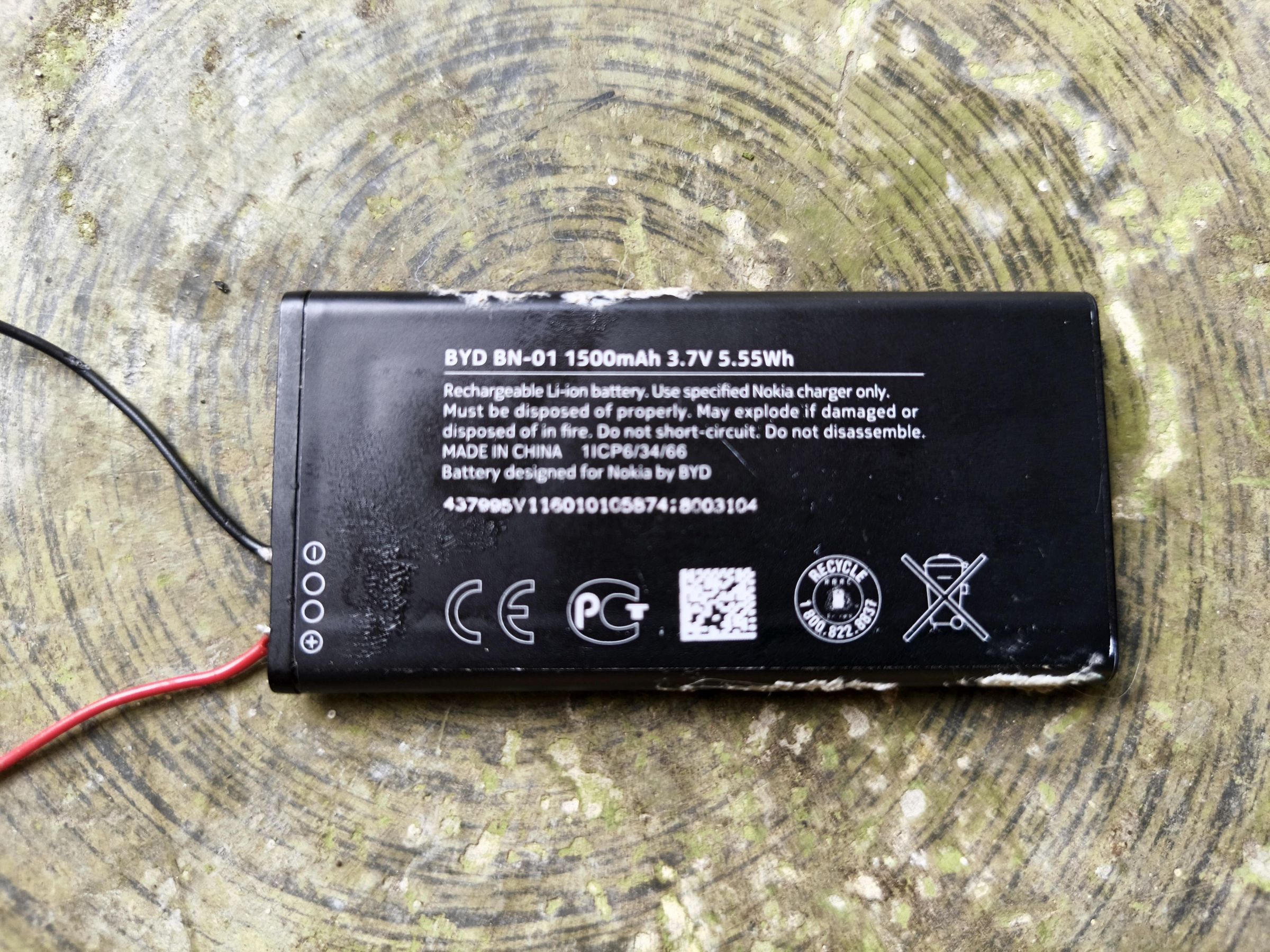
This step is optional if you have a lithium polymer battery with cables already on.
To solder on the phone battery, put some flux on the contacts labeled (+) and (-), and work quickly to feed the solder on the battery's contacts along with the cables.
Connect Everything Together
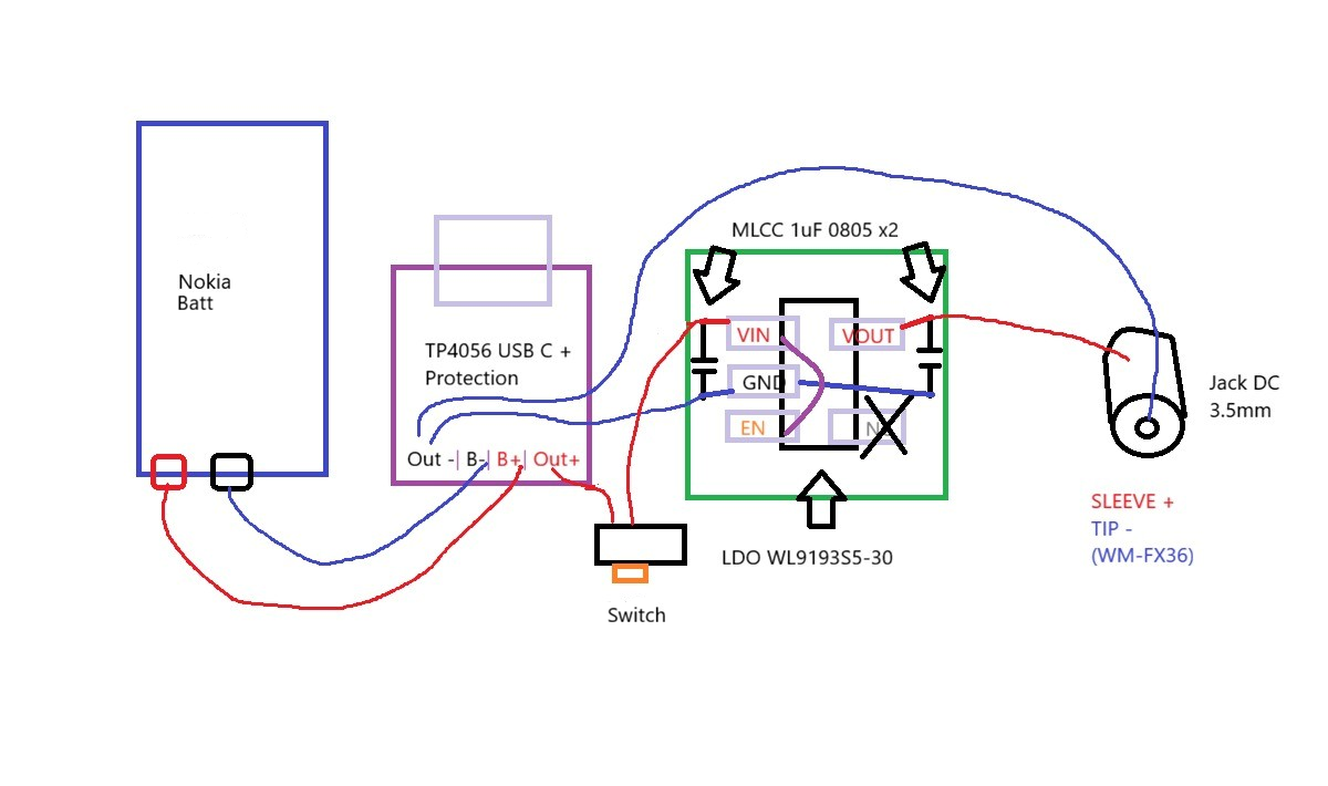
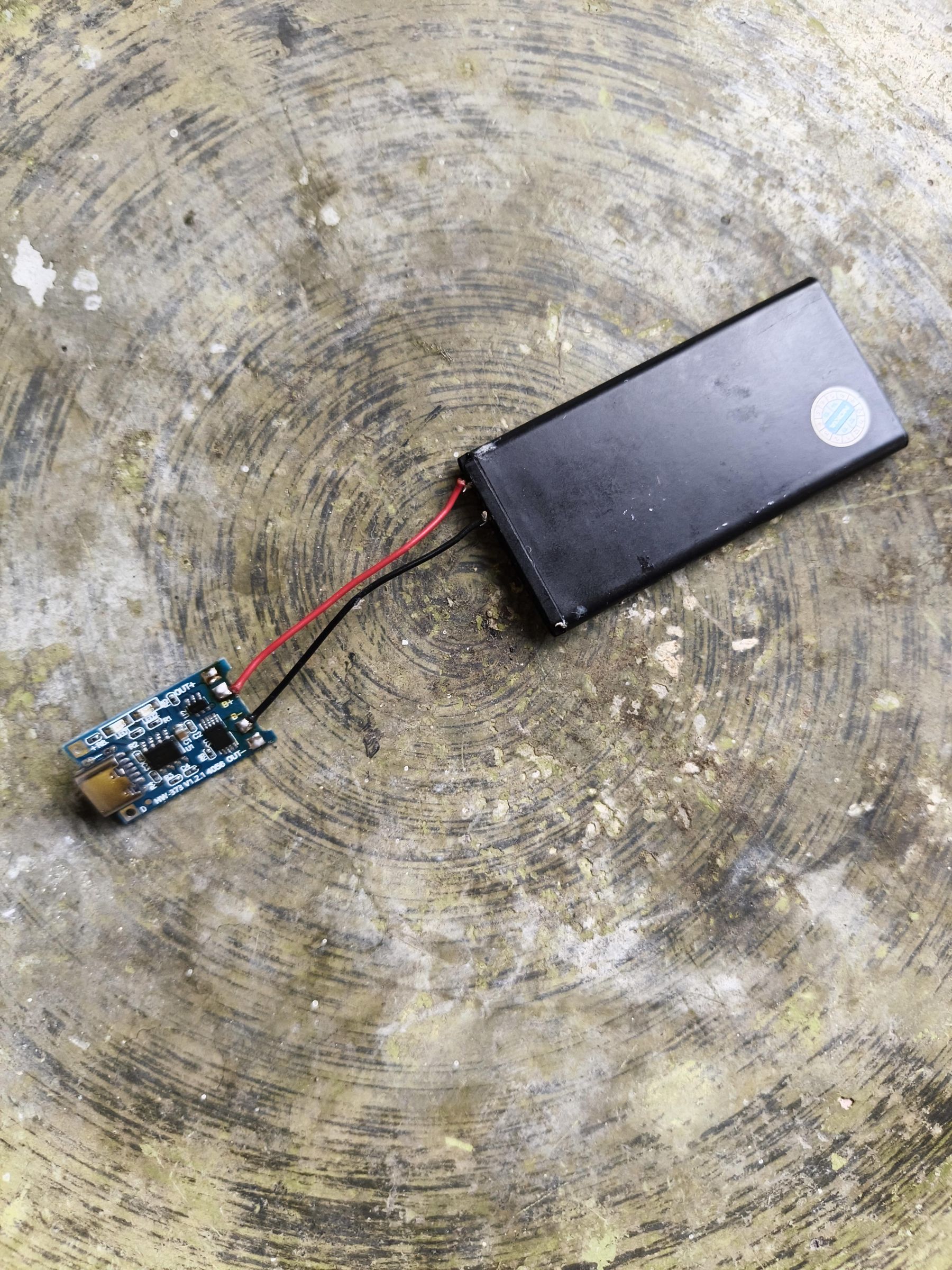
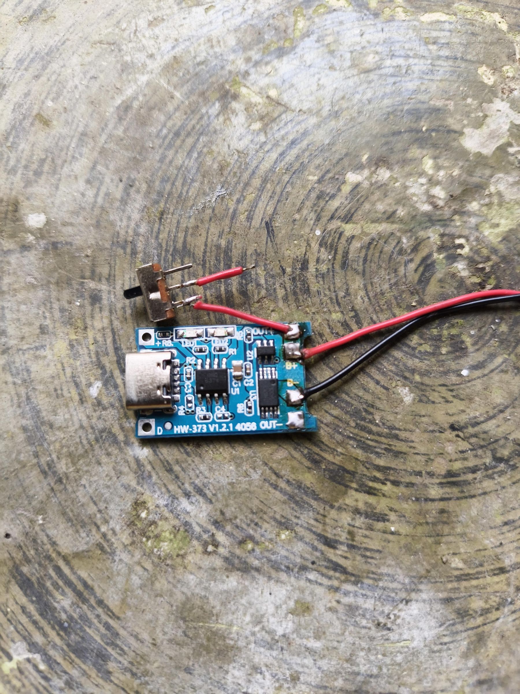
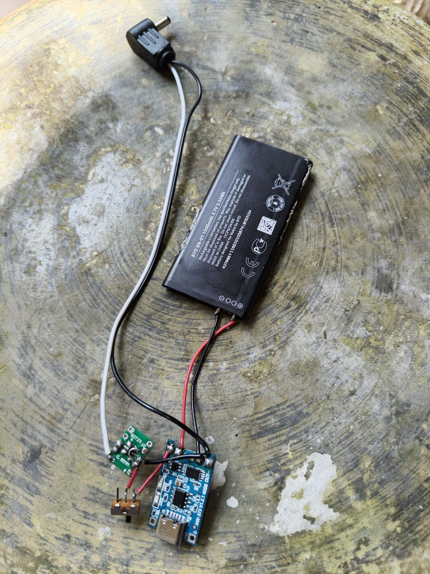
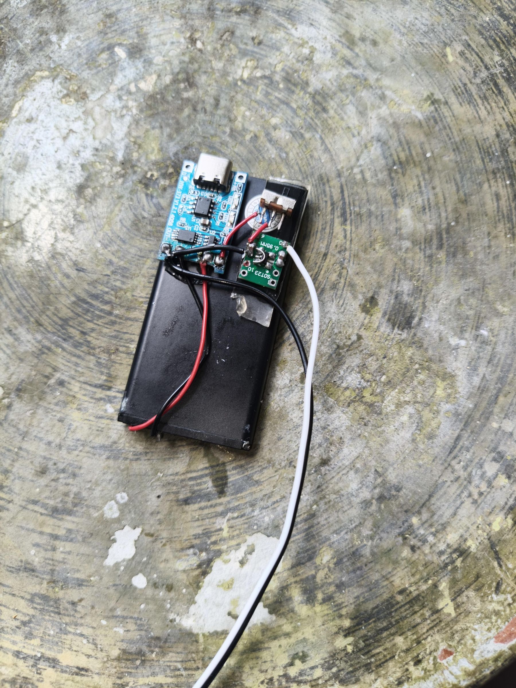
Solder the cable for the battery's positive rail to (B+), and the negative rail to (B-) of the TP4056 module. Then, solder the TP4056 module's OUT+ to VIN of the LDO module, and OUT- to the GND at the three pin side of the LDO with cables. Optionally, attach a switch between VIN and OUT+ to turn the circuit on and off. Solder the cables onto either the sides of the capacitor or the two vias under it.
Next, connect the output with the DC barrel jack and cable assembly. Solder VOUT to the VOUT cable, and solder the GND cable to the GND pin on the TP4056 board (for extra safety). Again, connect the cables onto either the sides of the capacitor or the two vias underneath it.
Finally, turn the switch on, and connect a multimeter set to voltage mode to the DC barrel jack to verify a 3V stable output! If it does, then congratulations! Plug it in and listen to some tunes.
TIP 4: Make sure the battery's charged up!
Mount It!
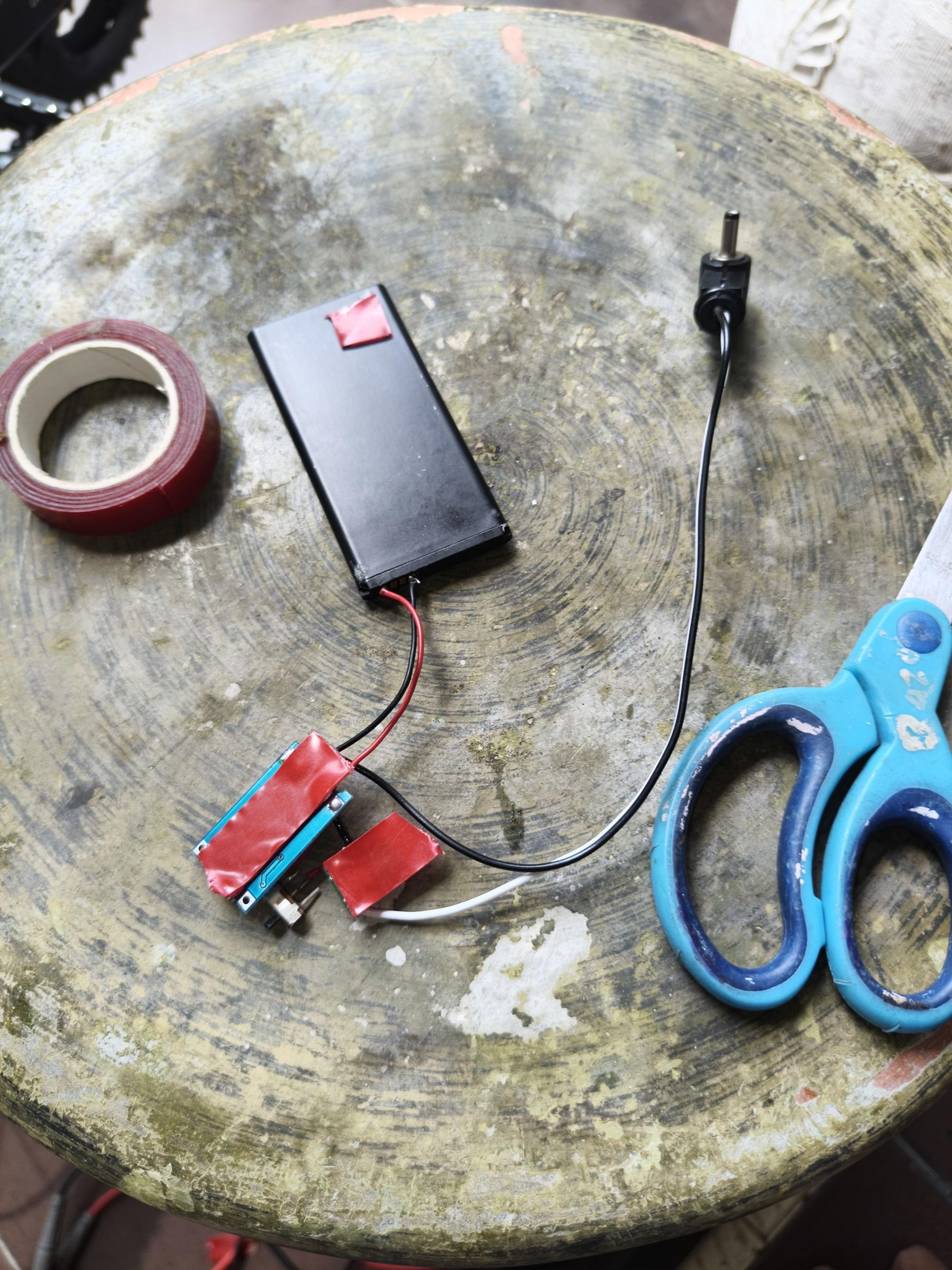
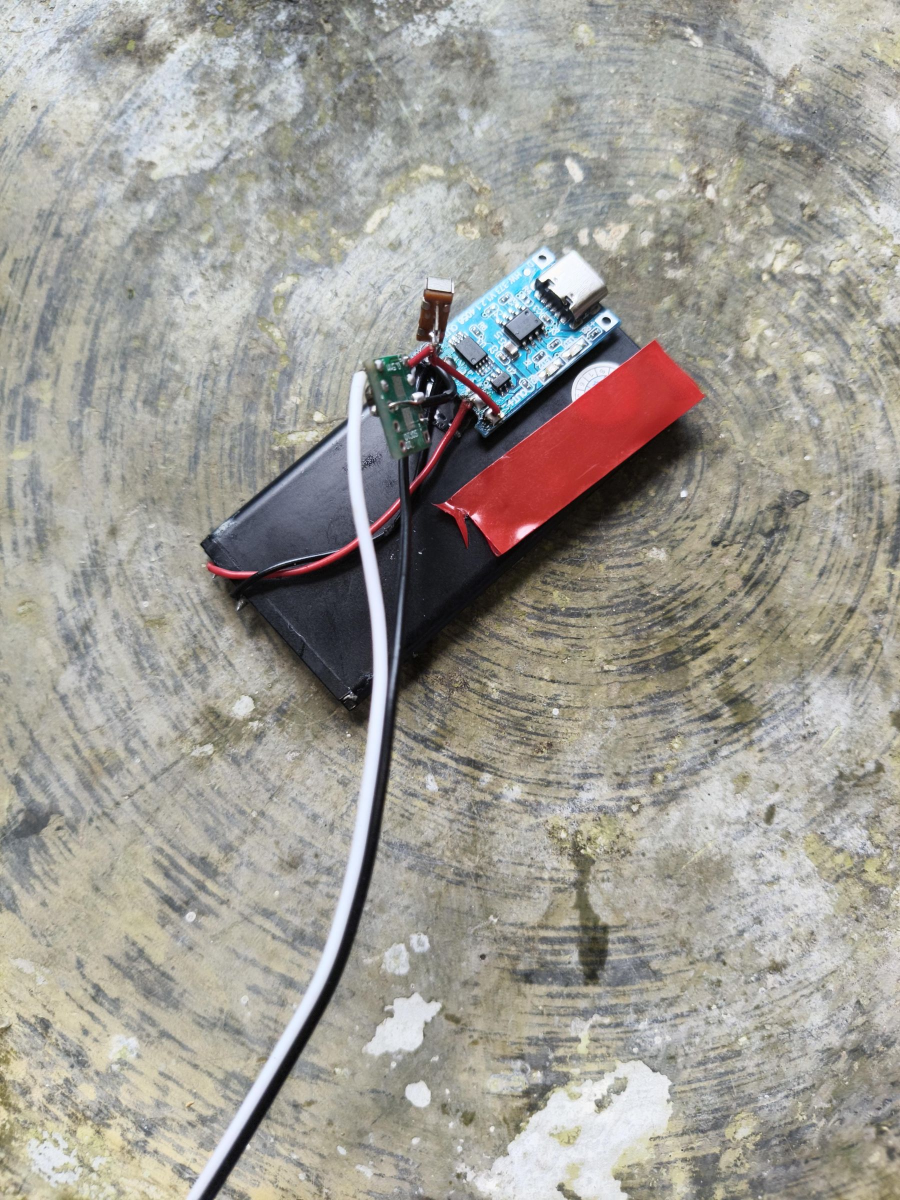
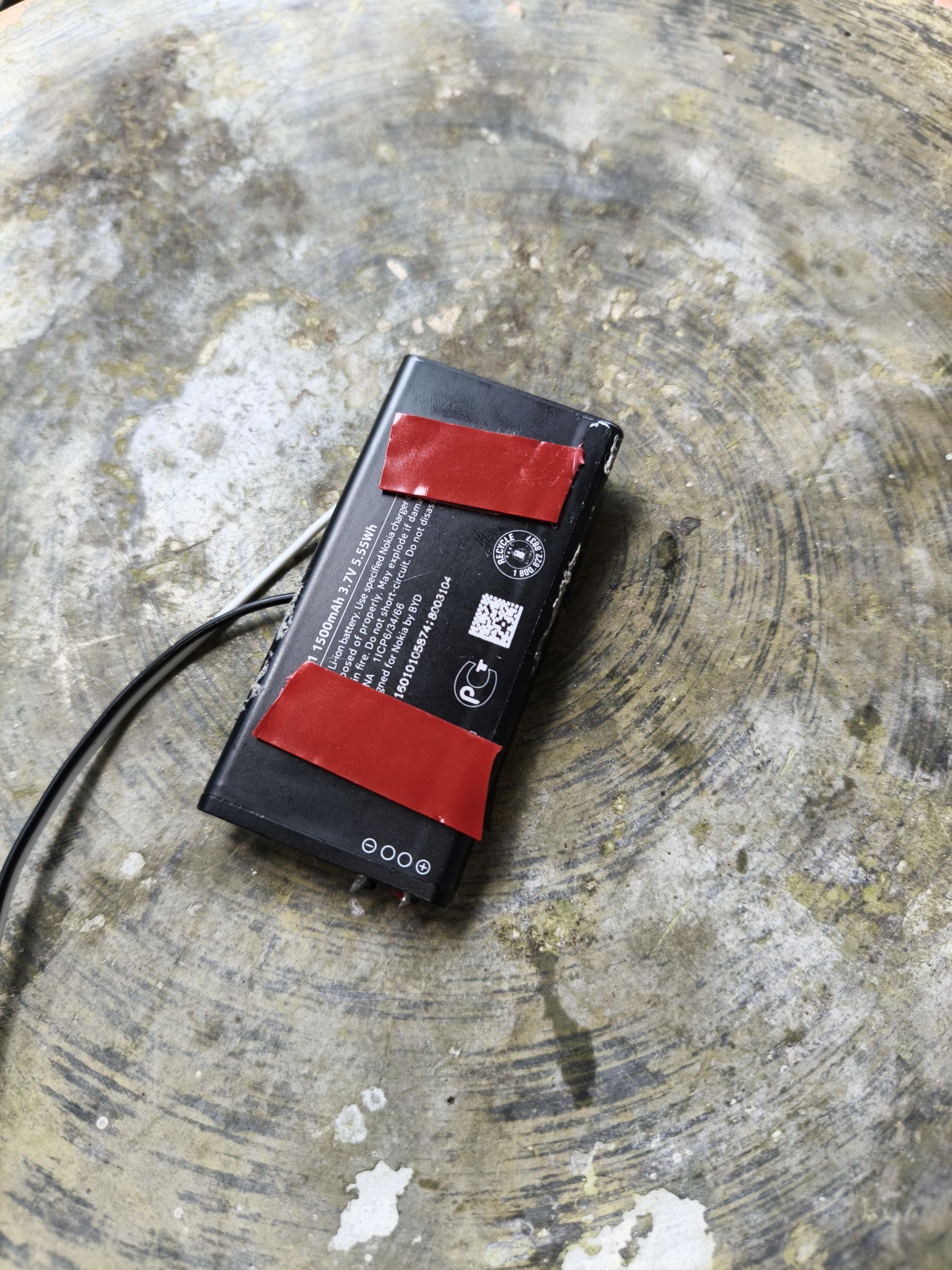
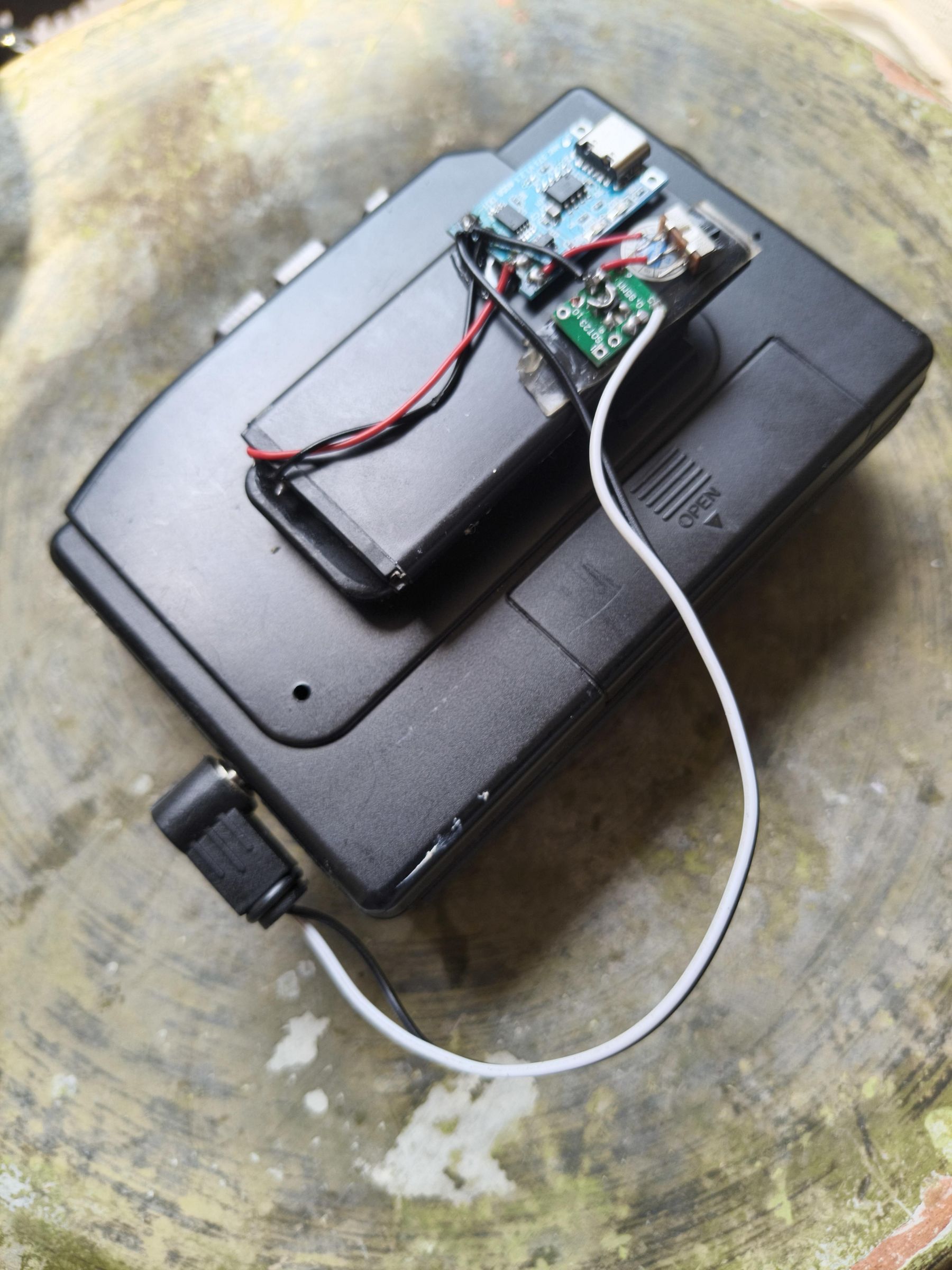
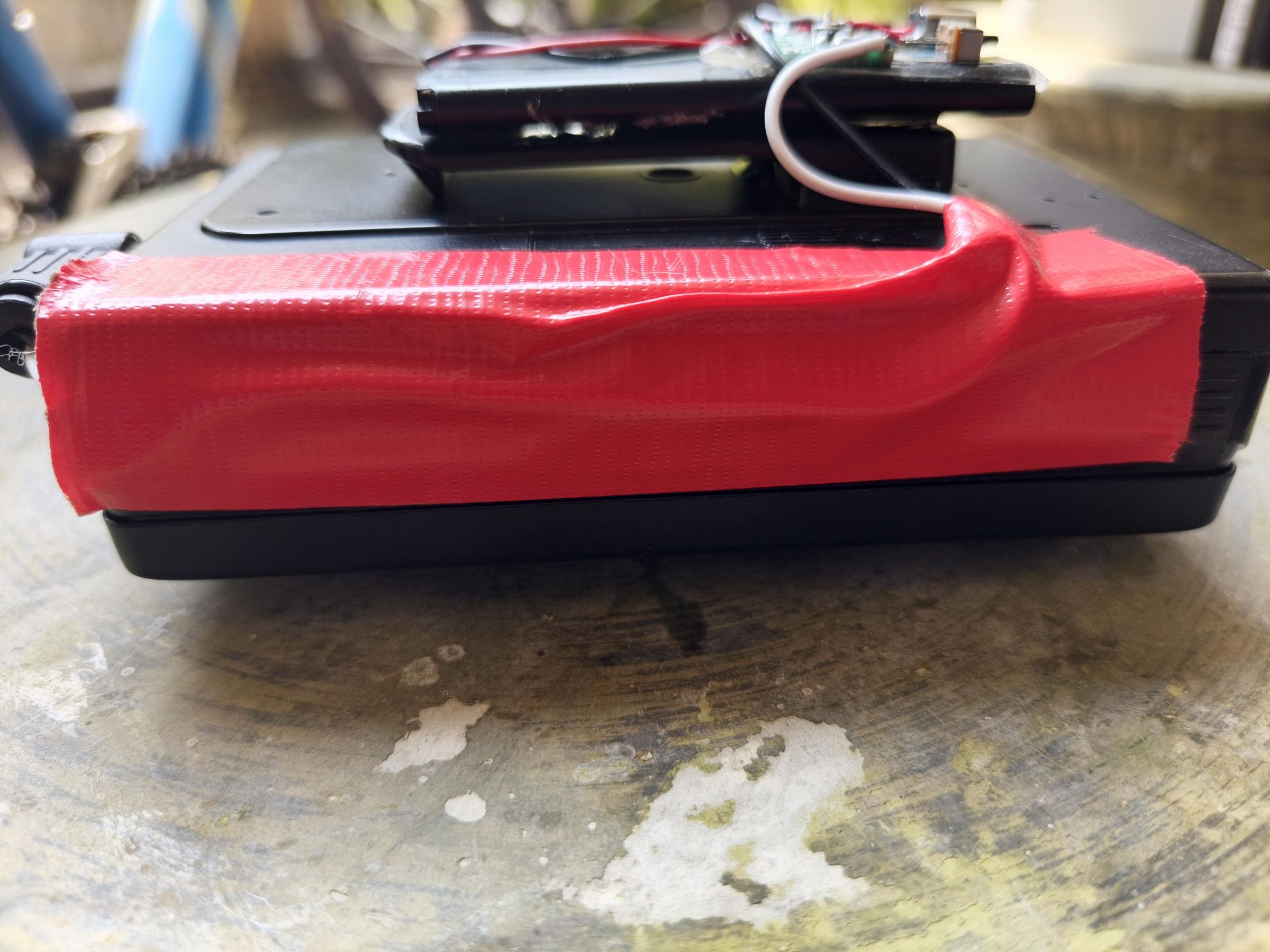
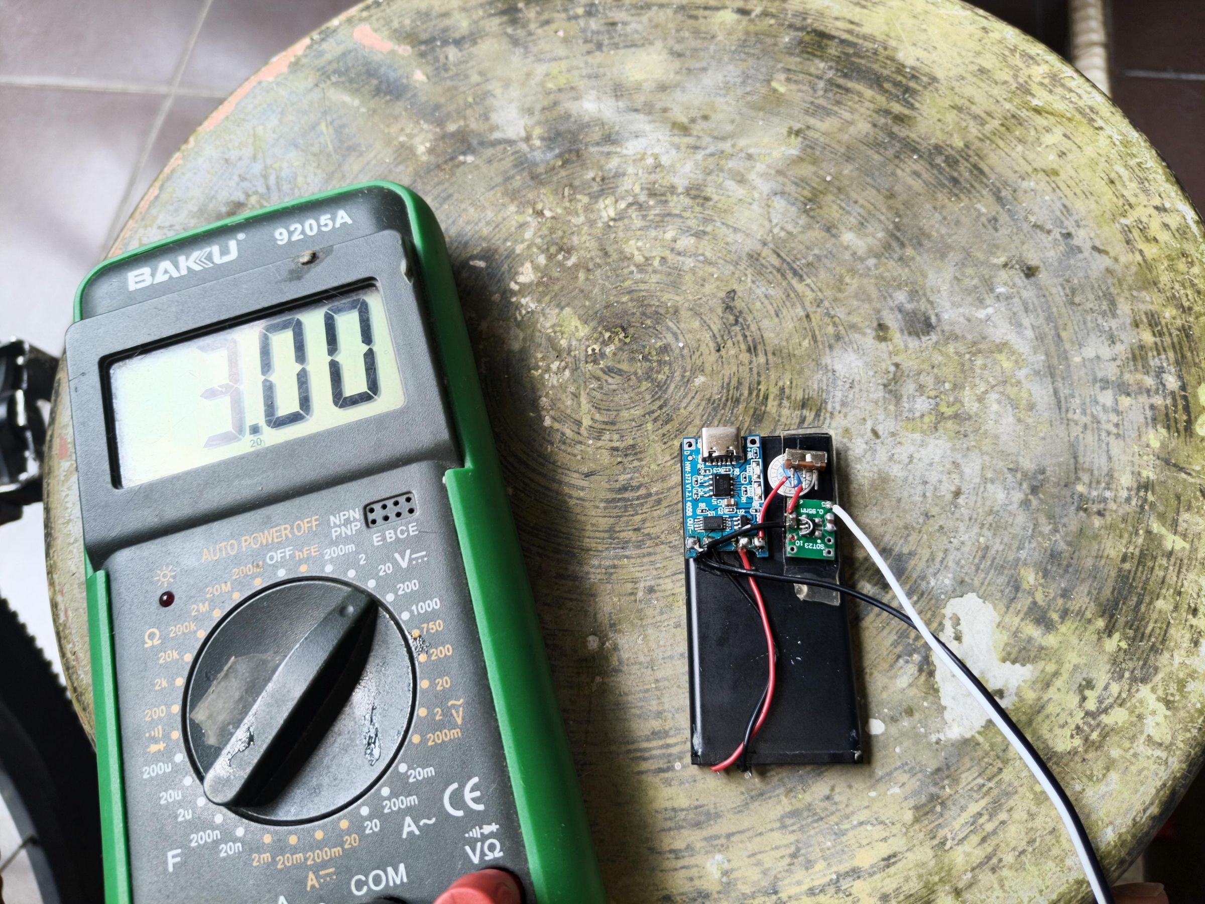
We're not quite done yet! If we leave this thing dangling all over the place, then we might risk shorts and broken connections. So let's mount everything on the battery first!
Put some mounting tape under the parts and press it to where it is most convenient to be placed.
In my setup, the TP4056 charging module goes on the lower section of the battery (the top here is where the contacts are). I recommend not placing the module in the middle of the battery so as to not obstruct charging with a charging cable.
Then, the switch goes right beside it (if installed). Mount the switch using mounting tape.
After that, the LDO module is placed above the switch (if installed). Also mount the module using mounting tape.
Finally, once everything is on the battery, tack on some mounting tape behind it and connect to the back of the cassette player via the belt clip. To organize the cable connected to the DC barrel jack, just tape the cables over with cloth tape.
Insert the barrel jack into the input, and test if it still runs!
Afterword
While this works for my cassette player, other players might required a modified assembly in order for things to still work.
I still have some lingering considerations, like using a 2.5V LDO instead of a 3V LDO simply because it is closer to the cutoff imposed by the DW01 on the TP4056 module and the cassette player would still accept a lower voltage like that.
In addition to using a 2.5V LDO, I am also considering adding a voltage supervisor to cut the voltage off of the LDO via the EN pin when it gets too low, as the DW01's over-discharge starts at 2.5V. Very low!
If you are willing, a comment addressing my lingering considerations or a critique will be greatly appreciated and very needed! This is my first Instructable, and I hope to gain more knowledge in the maker world from this experience!
This version of the project serves as "version 0" of a much more "polished" version I had made into a custom PCB that had already been fabricated and shipped here. However, due to the unavailability of a certain part from a local electronics store, I will have to make do for it via this Instructable and create an Instructable for "version 1" another time! Stay tuned and happy making!