PrismCast: a Custom-Built Ambilight Backlight
by ayushmaan45 in Circuits > LEDs
2853 Views, 36 Favorites, 0 Comments
PrismCast: a Custom-Built Ambilight Backlight
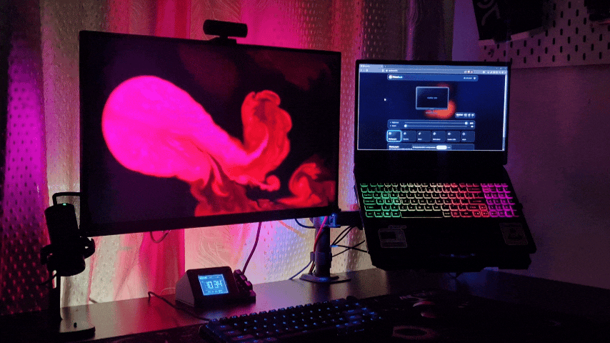
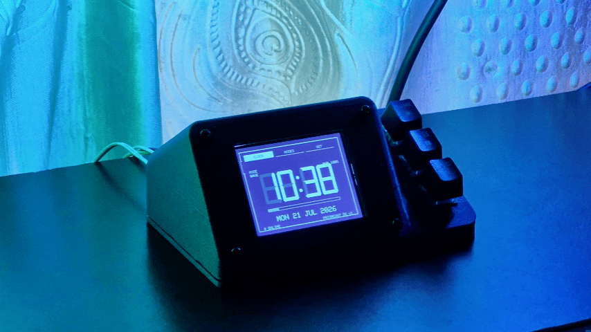
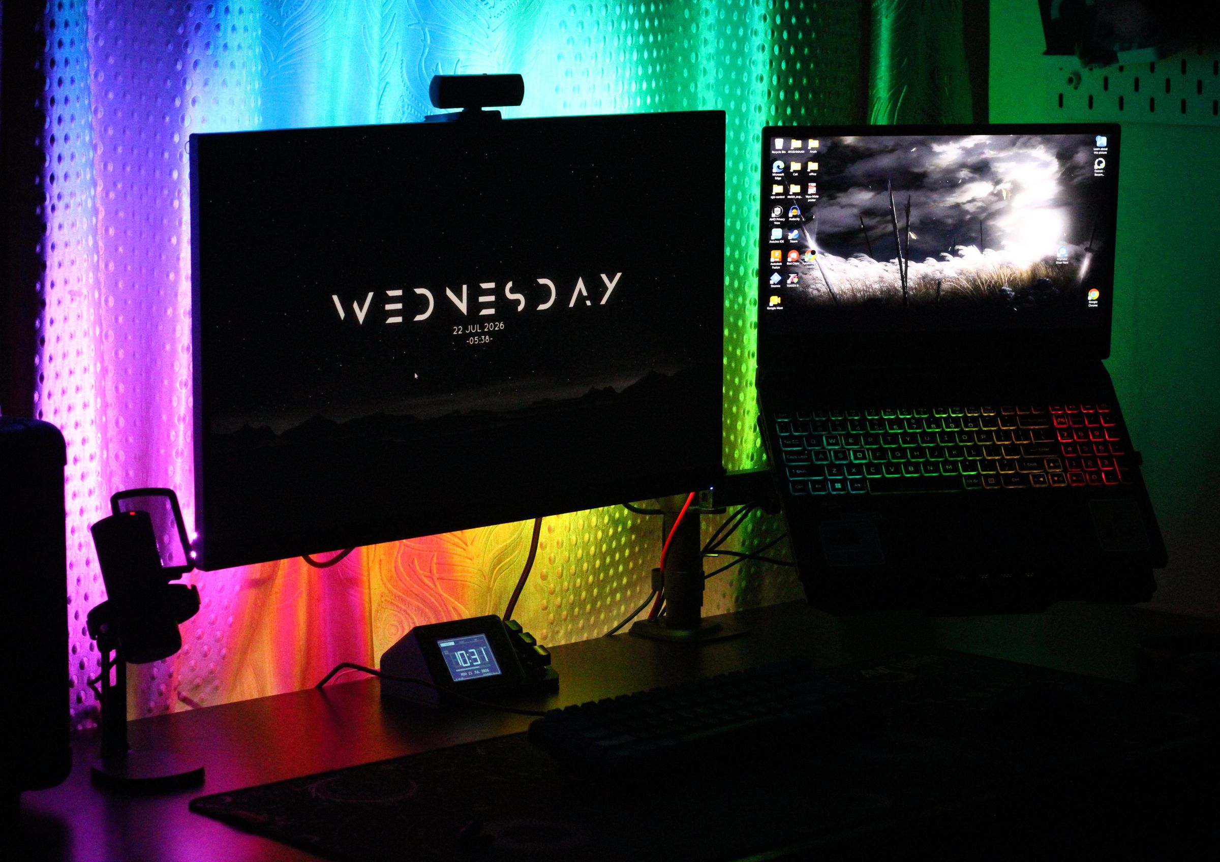
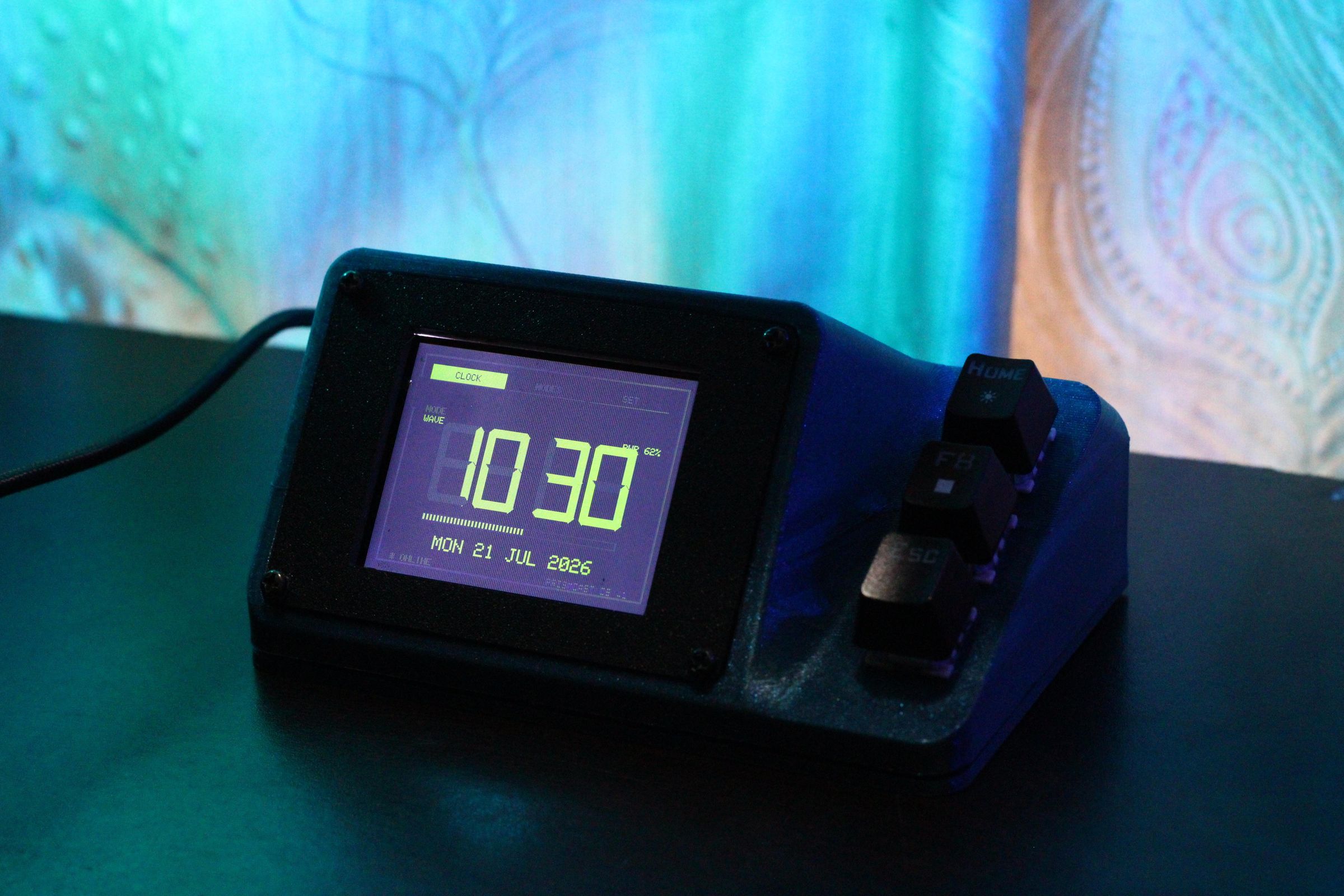
Hey everyone!
I'm Ayushmaan, and like most of my projects, this one started because I wanted something that felt like an actual product instead of a pile of wires taped to the back of a monitor.
I'd seen plenty of ambilight style backlight builds before strip some WS2812B LEDs behind a screen, flash WLED onto an ESP32, install Prismatik or Hyperion on the PC, and you're syncing lights to your display. It works, but it always felt like three separate tools stitched together rather than one thing. So I set out to build the whole stack myself instead: custom firmware, a custom browser-based control app, and a standalone desk device that's genuinely useful even with the PC turned off.
No WLED. No Prismatik. No Hyperion. Everything here — the firmware, the sync logic, the dashboard is built from scratch. There's a dedicated step further down that goes into exactly why, and what that trade-off actually looks like against the tools most similar builds rely on.
That's how PrismCast ended up being three projects in one — a monitor backlight, a real-time display-sync system, and a small desk clock — all running on a single ESP32.
The core idea:
- 120 individually addressable LEDs wrapped around the back of the monitor
- A browser web app that captures the screen live and streams matching colours to the strip — no desktop software to install, just open a webpage
- A standalone desk unit with its own screen and physical controls, so the device is still a fully working clock and lighting controller even without a PC connected at all
The desk unit turned into more than I originally planned. What started as "a box to hold the ESP32" became a small phosphor, terminal styled clock : the kind of glowing, monochrome CRT look you'd expect from an old terminal, except the colour shifts to match whatever lighting mode is currently running. Glance at the desk and you instantly know what the LEDs are doing, without even looking at the strip itself.
None of this was built in one clean pass. There's a proper "Problems Faced" step later covering the library that wouldn't compile, the display that mysteriously went white, the WiFi setting that broke WebSocket for a day, and the LED strip that lit up moving in exactly the wrong direction — because that's genuinely how most of it went.
This Instructable covers the whole build: the hardware and wiring, the LED installation, the firmware running on the ESP32, the web app that handles the display sync, and everything that broke along the way before it all came together.
Let's get into it
Supplies
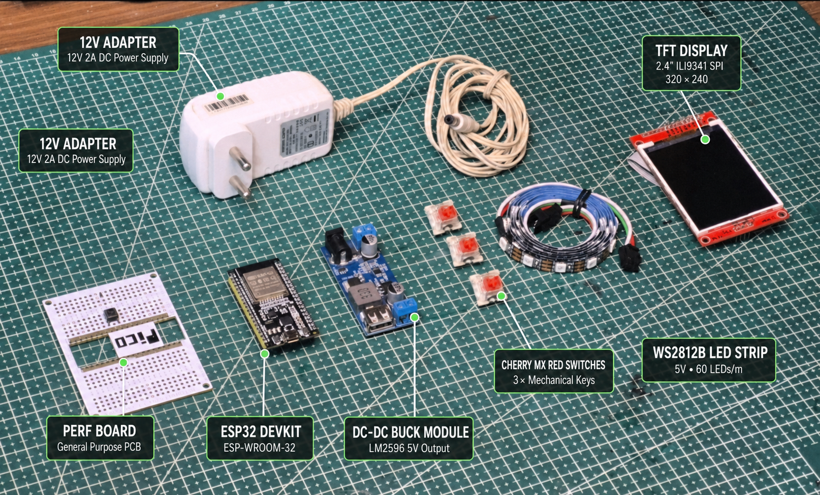
Supplies:
- ESP32 WROOM development board
- 2 × 1-meter WS2812B addressable LED strips, 60 LEDs/m
- 2.4-inch ILI9341 320 × 240 SPI TFT display
- 3 × Cherry MX Red mechanical keyboard switches
- HW-688 DC-DC buck converter
- Wires
- Connectors
- Perfboard
Why Build This From Scratch
Before writing a single line of firmware, the obvious question was whether to just use the tools everyone else uses for this kind of build — WLED on the ESP32 side, and Prismatik (or Hyperion) on the PC side for the actual screen-sync capture. Both are genuinely good, mature projects. I ended up not using either, and it's worth explaining why, since it shaped basically every decision after it.
What WLED and Prismatik Actually Do:
WLED is firmware that runs on an ESP32/ESP8266 and drives an LED strip — modes, effects, a web UI, and support for a handful of realtime protocols (like DDP or Adalight) that let other software feed it live colour data.
Prismatik (and Hyperion, its more actively maintained cousin) is a desktop app that captures the screen, averages the edge colours into zones, and streams the result to a device like a WLED strip over UDP or serial.
Put together, that's a complete ambilight system, and a lot of builds use exactly this combination — it's well documented, it works, and there's nothing wrong with it.
Why I Didn't Use Them:
- Desktop software is a real barrier. Prismatik/Hyperion both need to be installed, configured, and kept running in the background on the PC. That's an extra piece of software fighting for attention alongside whatever game or app is actually running — and it's one more thing that can silently stop working (crash, forget its settings, block on a Windows update) without an obvious reason why the lights aren't syncing anymore.
- Zone mapping is manual. Setting up Prismatik's capture zones means dragging rectangles onto a screen preview, one per LED, by hand. For 120 LEDs that's a genuinely tedious one-time setup, and it has to be redone if the monitor changes.
- WLED's UI is generic by design. It has to work for every kind of build, every strip length, every use case — which means it can't be shaped around one very specific thing, like a desk clock that also happens to control LEDs, with a screen whose colour follows whatever mode is active.
- I wanted to actually build the hard part. Screen capture, colour sampling, smoothing, a binary protocol, a device that renders its own UI — these are the parts of the project I was actually interested in solving myself, not gluing together configs for.
None of that is a criticism of either project — they solve a more general problem than what I needed, and solve it well. It just wasn't the problem I wanted to build.
What Building It From Scratch Actually Bought:
- Zero-install sync. The web app runs entirely in the browser. There's no companion app to install or keep running — open the page, click Start, done. If the sync stops working, closing and reopening a browser tab is the entire fix.
- Zone mapping is calculated, not dragged. Enter the monitor size and how many sides are covered, and the app works out exactly how many LEDs belong on each edge and where each one's sample zone sits — no manual placement.
- One connected system instead of two apps. Modes, brightness, colour, sync, and device settings all live in a single dashboard, talking to a single piece of firmware, instead of a lighting app and a separate capture app that don't know about each other.
- A device that's actually mine. The desk unit's phosphor-terminal look, the way its screen colour follows the active mode, the fact that it's a real clock and not just an LED controller with a screen bolted on — none of that comes for free with off-the-shelf firmware. It only exists because the whole stack was open to change.
The Trade-off, Honestly:
This approach costs real time. WLED and Prismatik are mature, tested by thousands of users, and handle edge cases I had to discover the hard way — most of the "Problems Faced" step later in this Instructable is stuff that WLED or Prismatik would have already solved for me. Building it from scratch means owning every one of those bugs myself, and a first-time build like this is never going to have the same polish as software that's been iterated on for years by a much larger group of people.
If the goal was just "get an ambilight working this weekend," WLED plus Prismatik is the faster and honestly the more sensible answer. This project was never really about the fastest path, though — it was about ending up with something that felt like a cohesive product I built end to end, not a config file for someone else's software.
The Concept
Before opening Fusion 360 or soldering a single wire, I spent some time thinking about what I actually wanted PrismCast to be. I didn't want it to be just another RGB monitor backlight. I wanted it to feel like a complete desk accessory — something fun to use every day, not just a strip of LEDs glowing behind a screen.
Instead of modifying an existing project, I challenged myself to build the entire system from scratch. more on why in the next step. That meant writing my own firmware, designing a custom web dashboard, creating the device's own interface, and even designing and printing the enclosure myself.
The biggest feature of PrismCast is its browser-based display synchronization. A custom web app captures the screen, samples the colours around the edges, and wirelessly sends them to the ESP32, which updates the LEDs behind the monitor in real time. Since everything runs through the browser, there's no dedicated desktop software to install — just open a webpage and it works.
I also wanted the project to stay genuinely useful when display sync wasn't even running. That's why the controller has its own 2.4-inch TFT display and three mechanical switches, so lighting modes, brightness, and colours can all be changed without ever touching the browser. And when I want finer control, the web dashboard opens up the deeper stuff — per-LED editing, monitor layout configuration, custom colour controls, and preset management.
Features:
- Browser-based display synchronization
- No dedicated desktop software required
- Built completely from scratch
- Custom ESP32 firmware
- Standalone controller with a 2.4-inch TFT display
- Three mechanical switches for quick controls
- Multiple built-in lighting effects
- Advanced browser dashboard
- Per-LED customization
- Support for different monitor sizes and layouts
- Custom 3D-printed enclosure
- Futuristic desk clock interface
With the concept finalized, it was finally time to start designing the enclosure that would bring everything together.
Designing the Enclosure
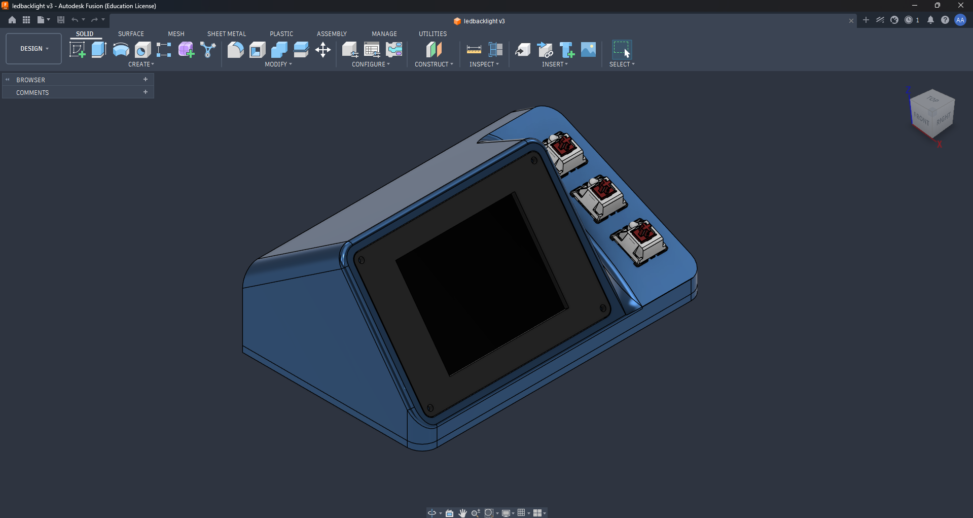
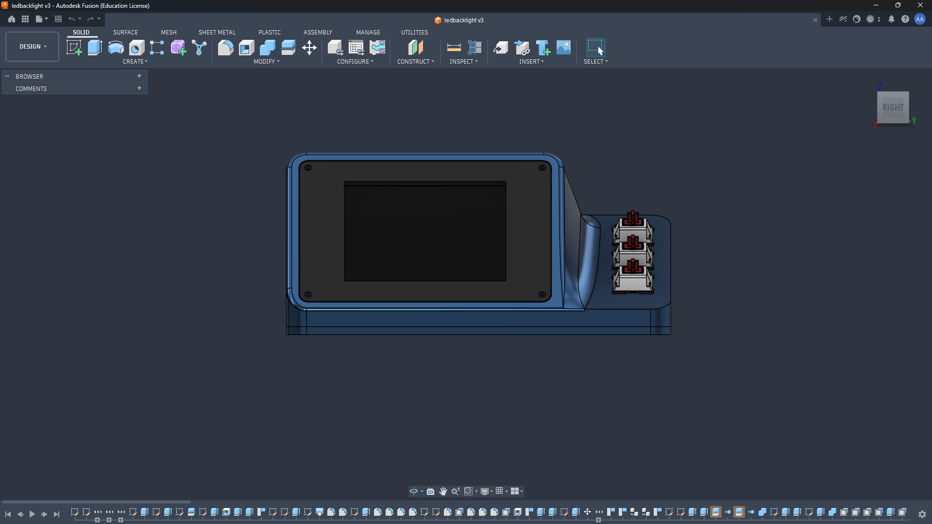
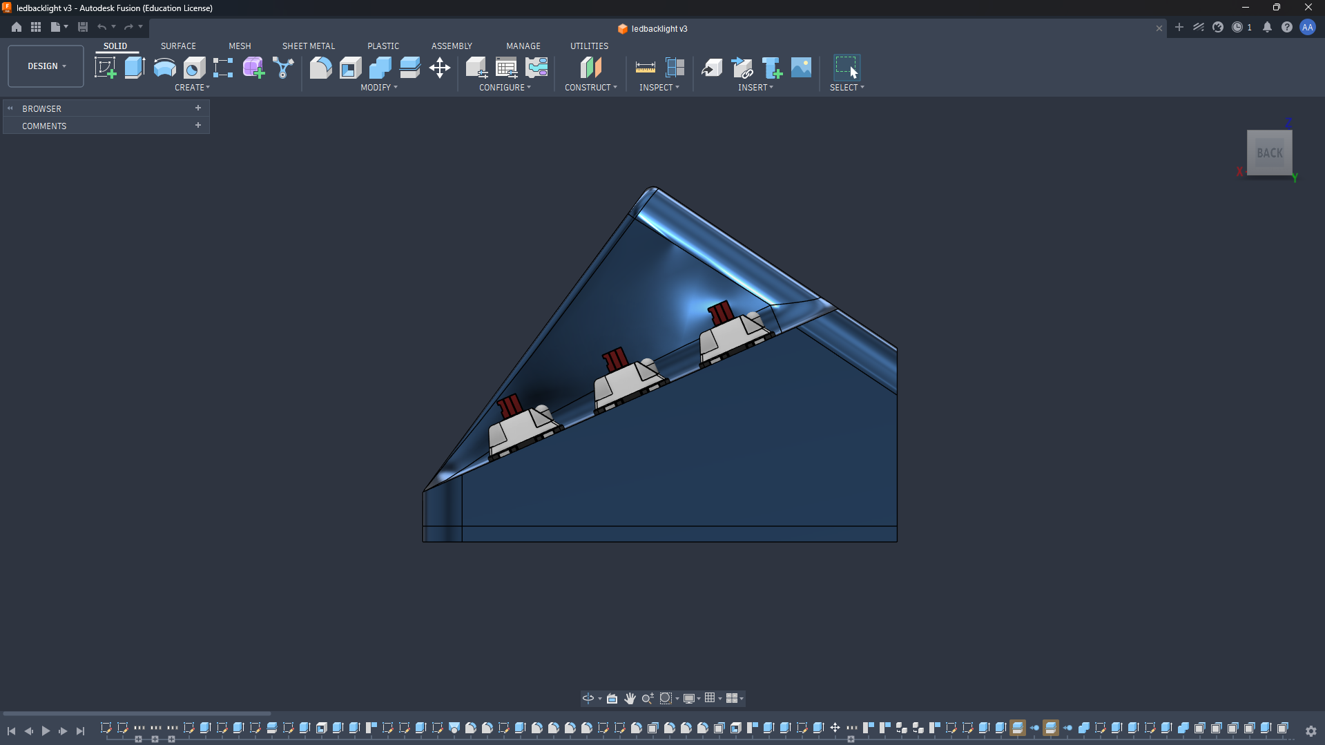
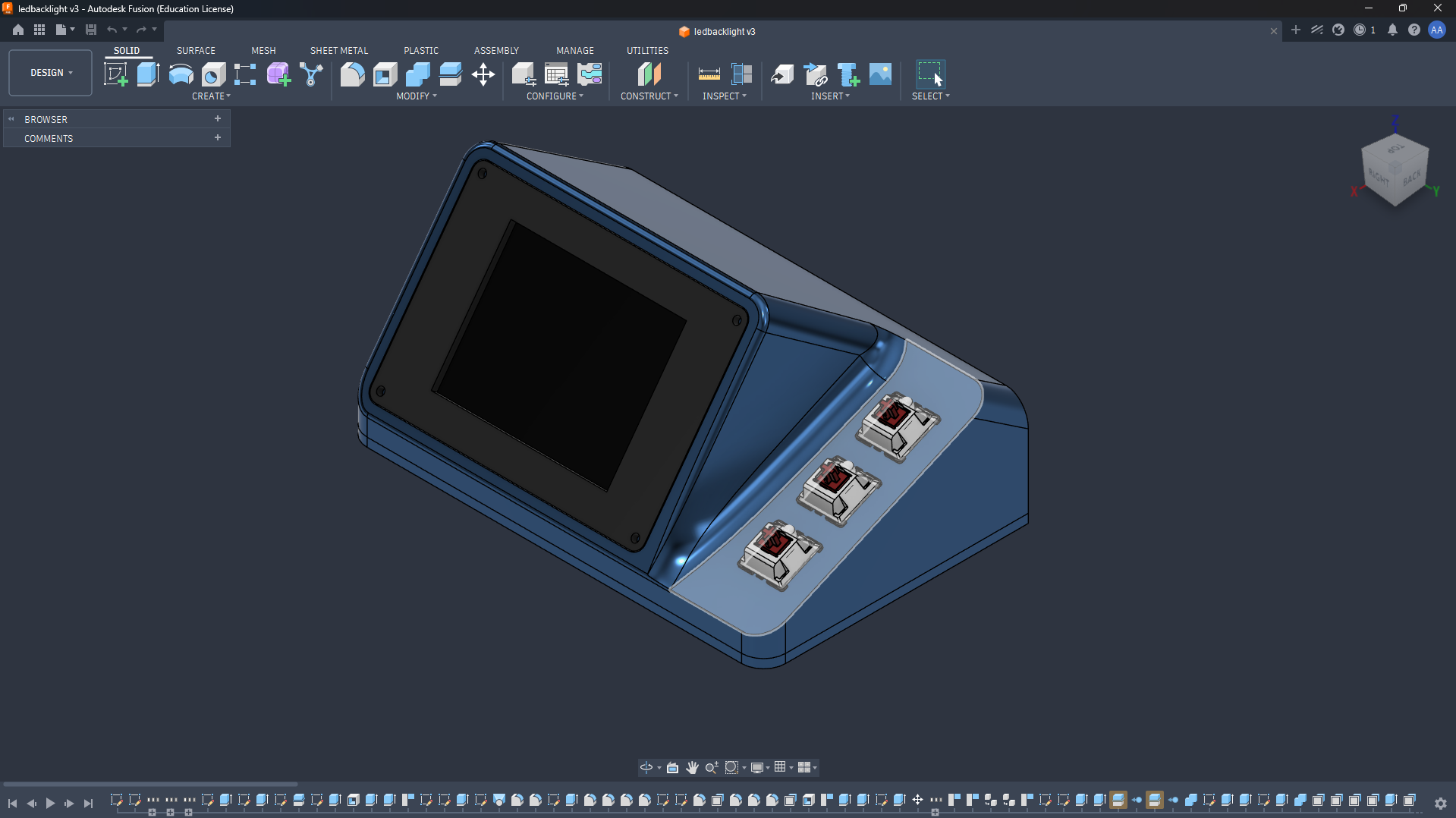
Since PrismCast was designed to stay on my desk, I wanted it to look more like a modern desk accessory than a typical DIY electronics project. While looking for inspiration, I came across the HiDock, and I really liked its clean, minimal design with an angled front. Using that as inspiration, I designed a completely custom enclosure in Fusion 360 around the hardware I was using.
The enclosure consists of three separate parts: the top housing, the bottom cover, and a dedicated display mounting plate. Mounting the TFT on its own plate made assembly much easier and ensured the display sat perfectly aligned with the front opening.
The front houses the 2.4-inch TFT display on the left and the three mechanical switches on the right, while the internal layout was designed to neatly accommodate the ESP32 and the rest of the electronics.
After a few iterations to fine-tune the dimensions and internal clearances, I was happy with the final design.
3D Printing
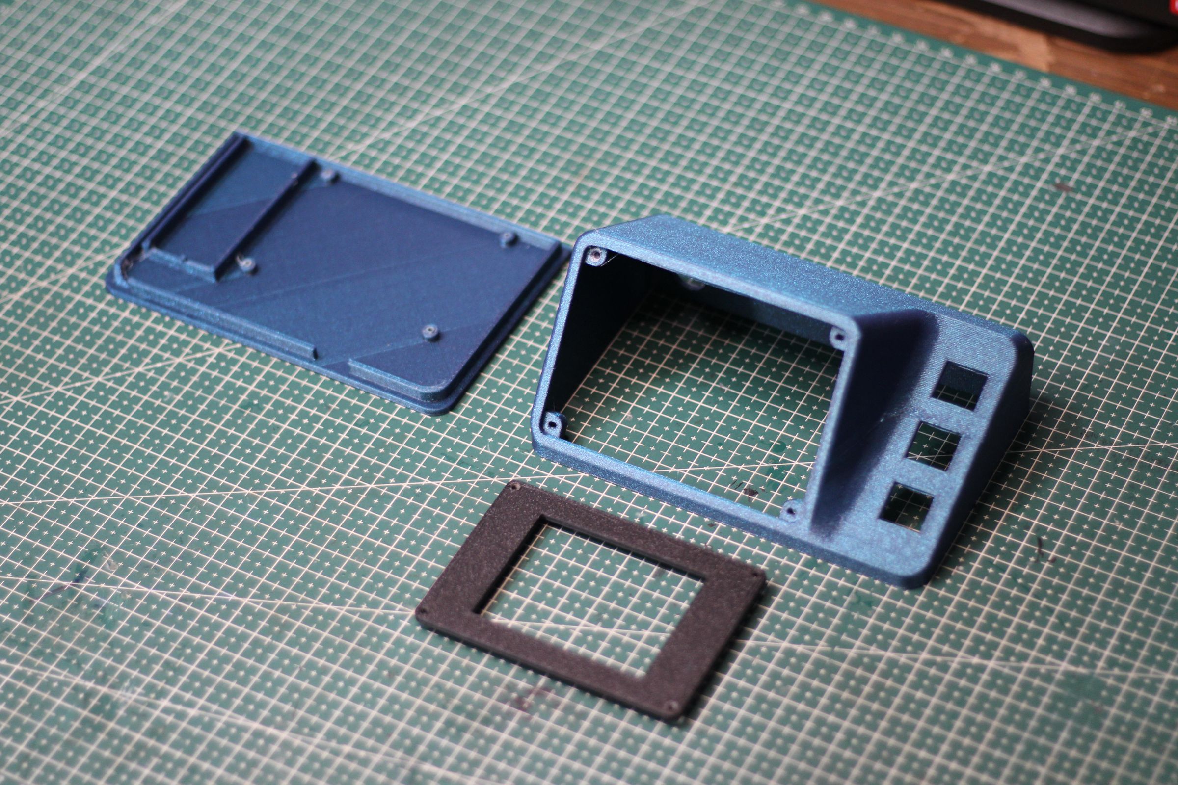

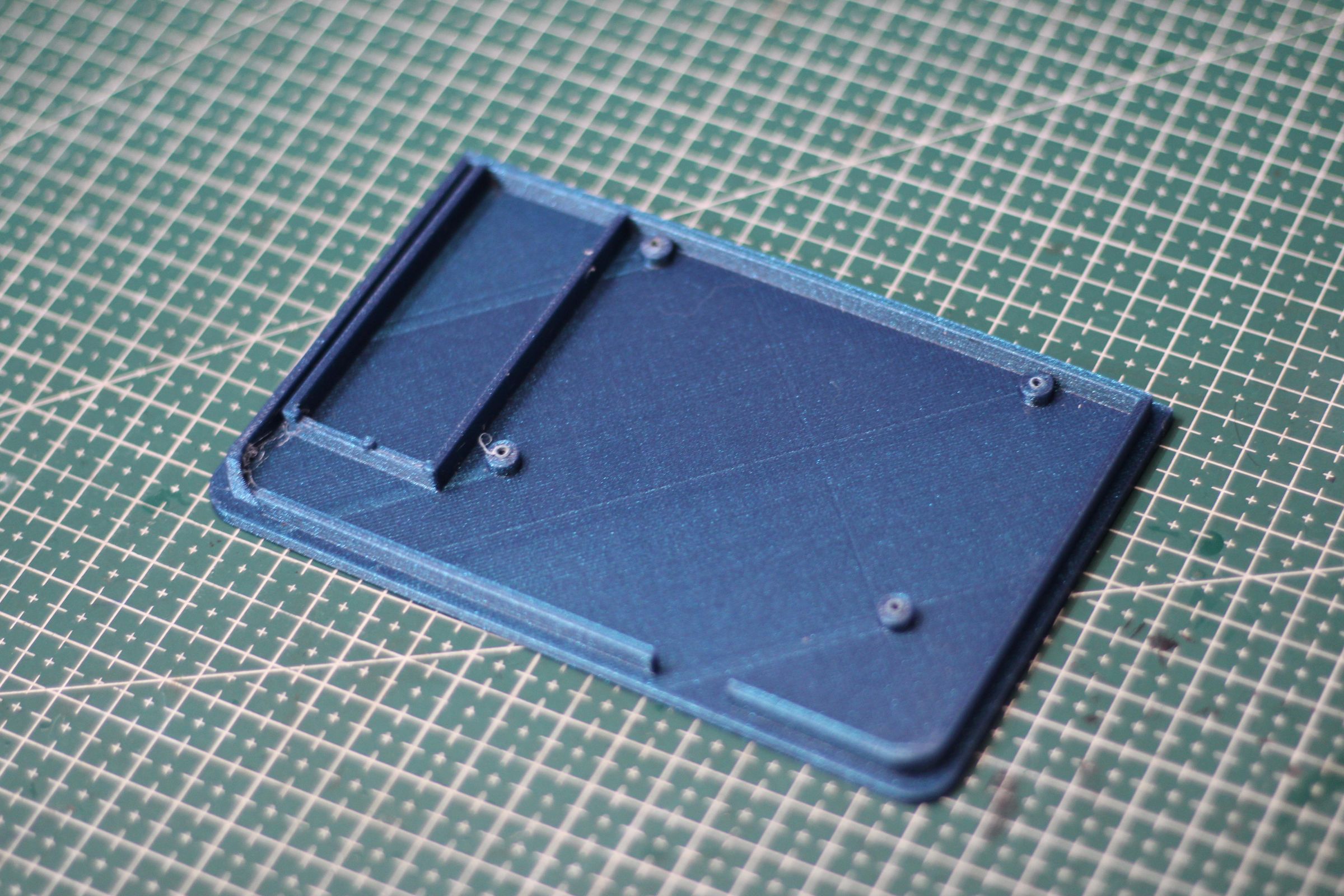
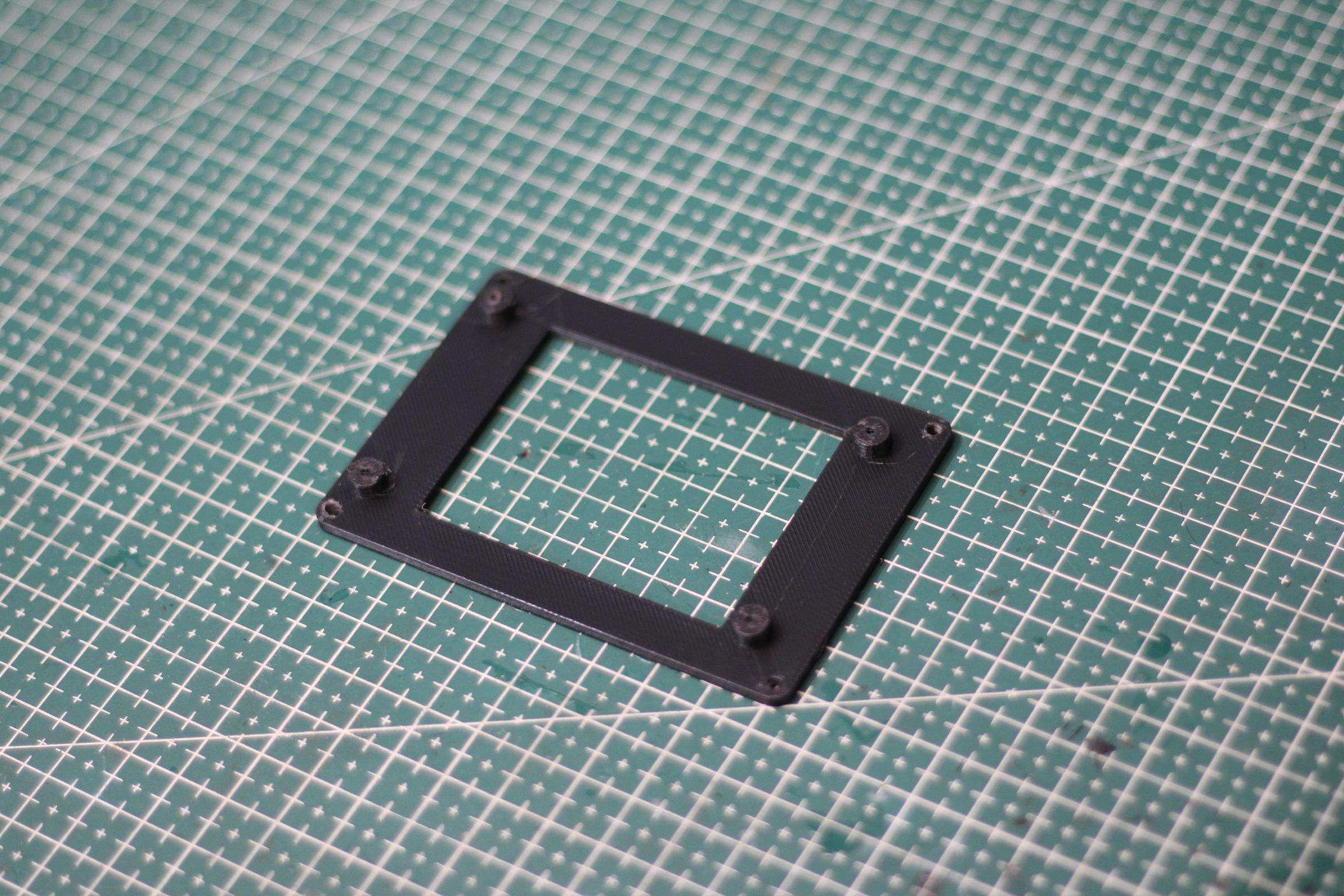
With the design finalized, it was time to bring PrismCast to life.
The enclosure was printed on my Anycubic Kobra S1. For the main body, I used Blue Sparkle PLA, while the display mounting plate was printed using Black Rapid PLA to give the front of the device a clean contrast.
Since the enclosure consists of three separate parts—the top housing, bottom cover, and display mounting plate—I printed each part individually before cleaning up the supports and test-fitting the hardware.
Before moving on to the electronics, I checked that the TFT display, mechanical switches, and other components fit correctly. Thankfully, everything aligned perfectly, making the final assembly much easier.
Printer: Anycubic Kobra S1
Materials:
- Blue Sparkle PLA (Top Housing & Bottom Cover)
- Black Rapid PLA (Display Mount)
Slicer: Anycubic Slicer Next (or Bambu Studio if you actually sliced it there)
Installing the LED Strip
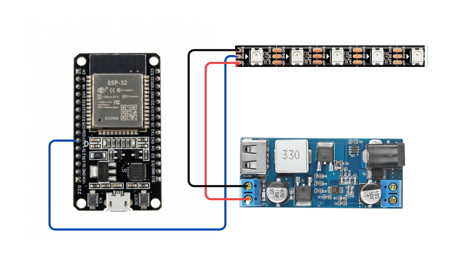
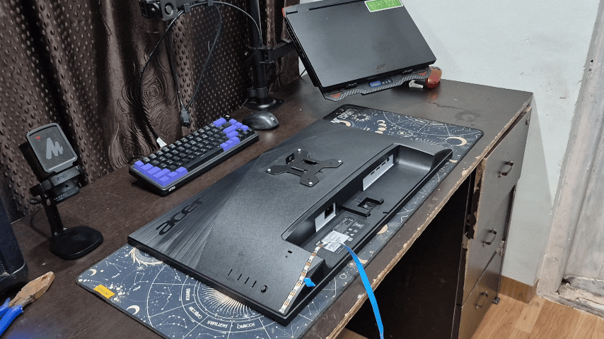
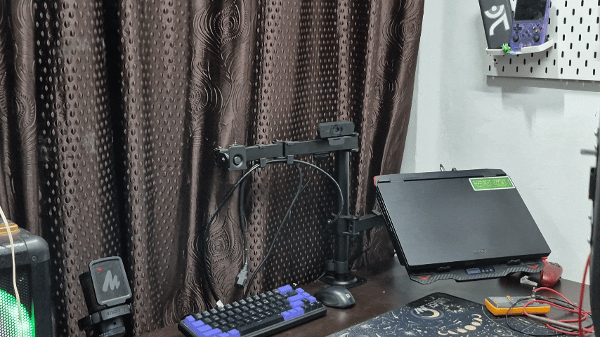
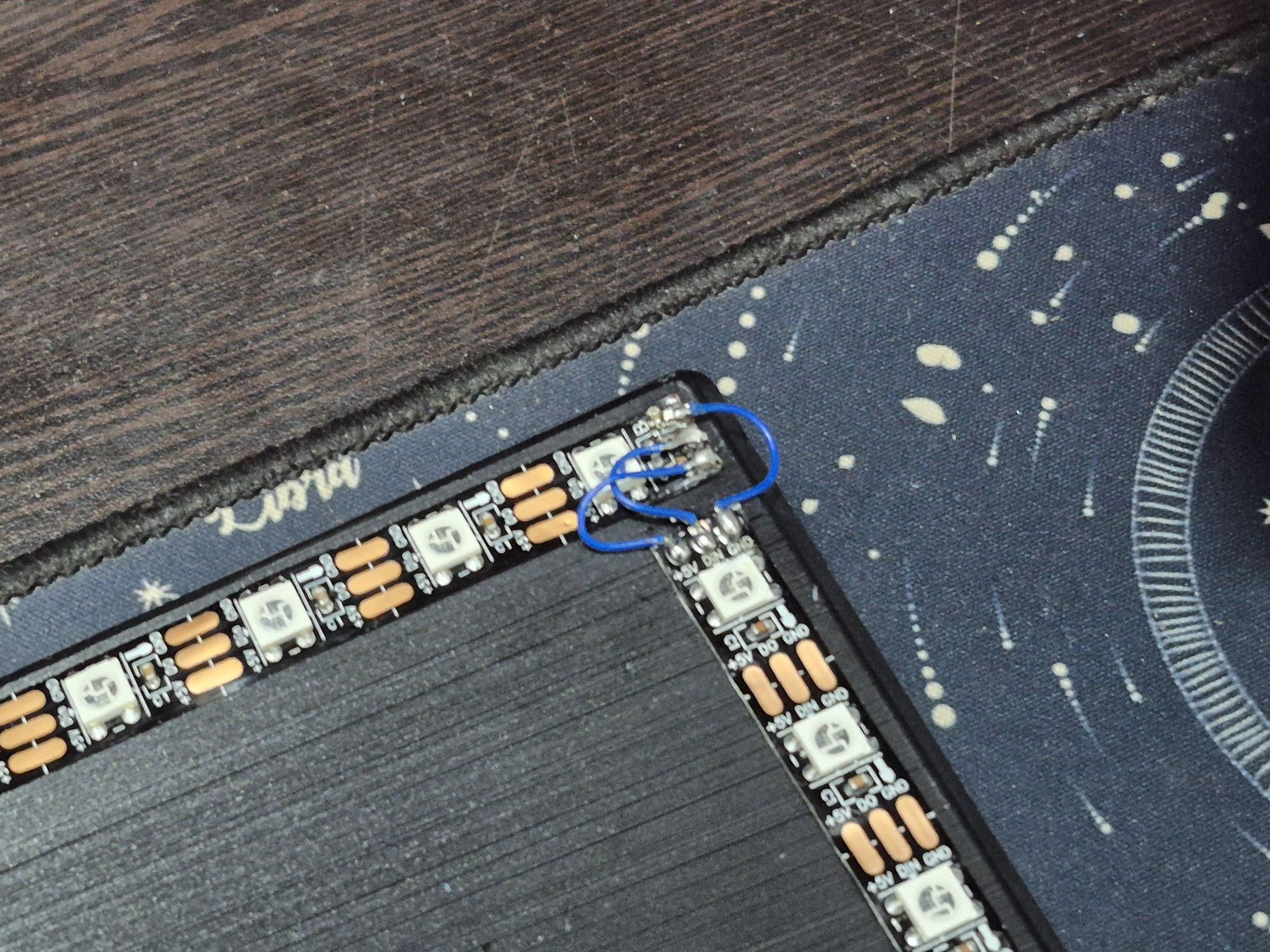
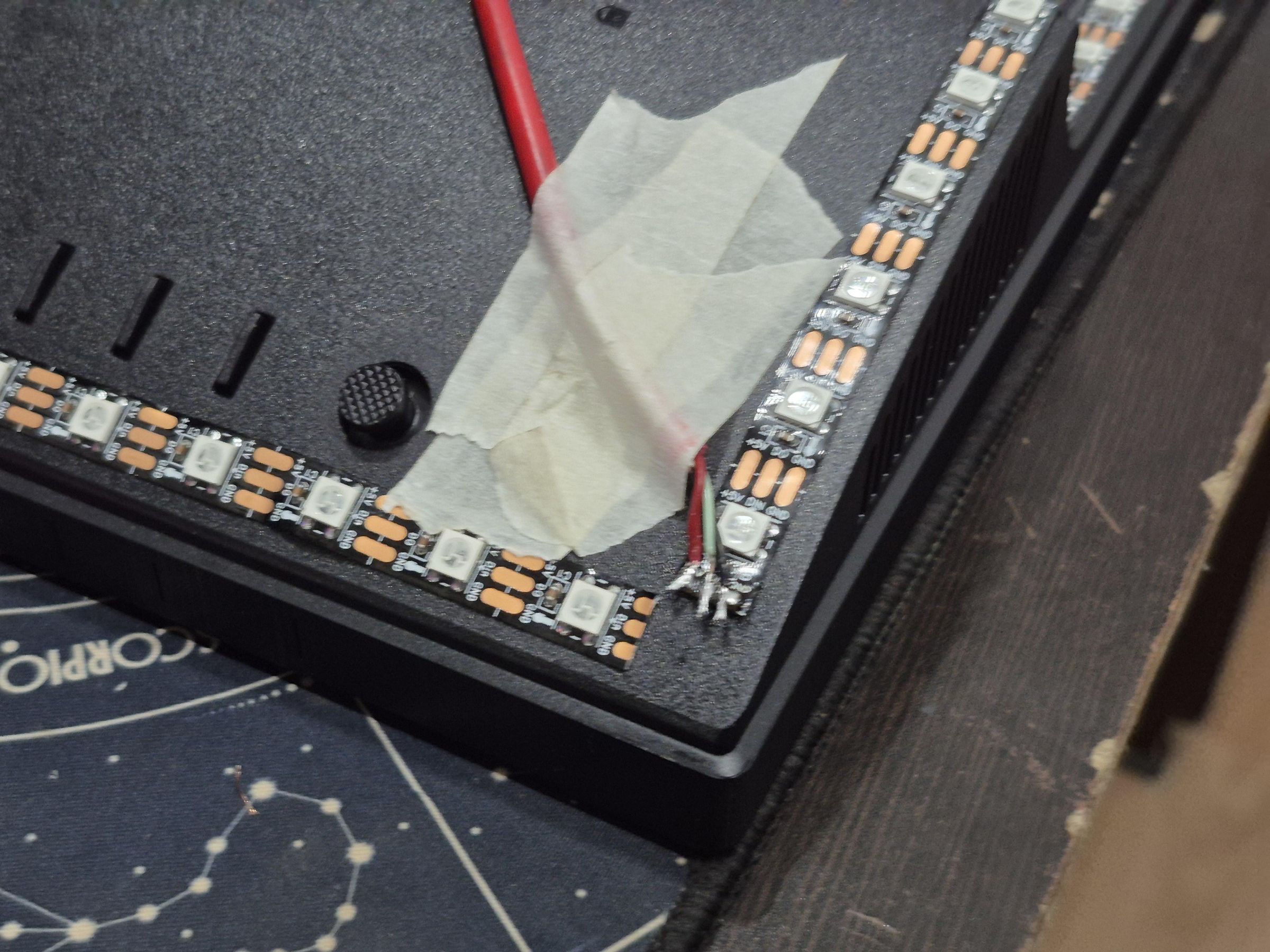
The backlight uses two 1-metre WS2812B strips (60 LEDs/m), soldered together end to end to make one continuous 120-LED run, mounted around the back of the monitor. Getting the physical placement and wiring order right up front saved a lot of software-side confusion later, since the web app assumes a specific direction around the strip.
1. Working Out How Many LEDs Per Side
At 60 LEDs/m, the spacing between LEDs is about 16.67mm. For a 27" monitor (roughly 598mm wide, 336mm tall active area), that works out to:
- Top: 36 LEDs
- Bottom: 36 LEDs
- Left: 20 LEDs
- Right: 20 LEDs
which adds up to 112 out of the 120 available — leaving a small amount of slack strip to work with around the corners instead of coming up short.
If you'd rather skip the bottom edge (useful if the monitor stand blocks the glow anyway), the same math without the bottom edge works out to about 76 LEDs for a 27" screen.
2. Deciding the Wiring Direction
This part matters more than it seems like it should — the strip's data line only runs in one direction, and whatever order it's physically wired in has to match the order the web app expects, or the sync colours land on the wrong edges entirely.
I settled on: data-in at the top-left corner, running clockwise — across the top left-to-right, down the right side, across the bottom right-to-left, up the left side back to the start.
Marking the intended direction on the monitor with tape before cutting or soldering anything saved a lot of second-guessing later.
3. Joining the Two Strips
Since one strip only covers 1 metre, the two get joined end to end with three wires — data out from strip 1 to data in on strip 2, plus 5V and GND continued across the join:
- Strip 1 DOUT → Strip 2 DIN
- Strip 1 5V → Strip 2 5V
- Strip 1 GND → Strip 2 GND
From the firmware and web app's point of view, this reads as one continuous 120-LED strip — there's no code difference between one long strip and two joined ones, as long as the data direction carries through correctly at the join.
4. Power Injection
WS2812B strips lose voltage over their length as current draws down the copper traces, especially toward the far end of a 2-metre run — the practical symptom is LEDs near the end looking dimmer or slightly off-colour (usually reddish) compared to the start.
To avoid that, power was injected at both ends of the combined run rather than relying on the strip's own thin copper to carry current the whole way:
- 5V and GND wired in at the start (near the data-in end)
- 5V and GND wired in again at the very end of the strip
Both connect back to the same buck converter output, just via separate wire runs rather than daisy-chained through the strip itself.
The Circuit
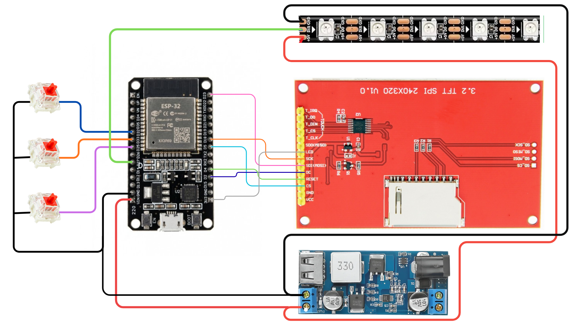
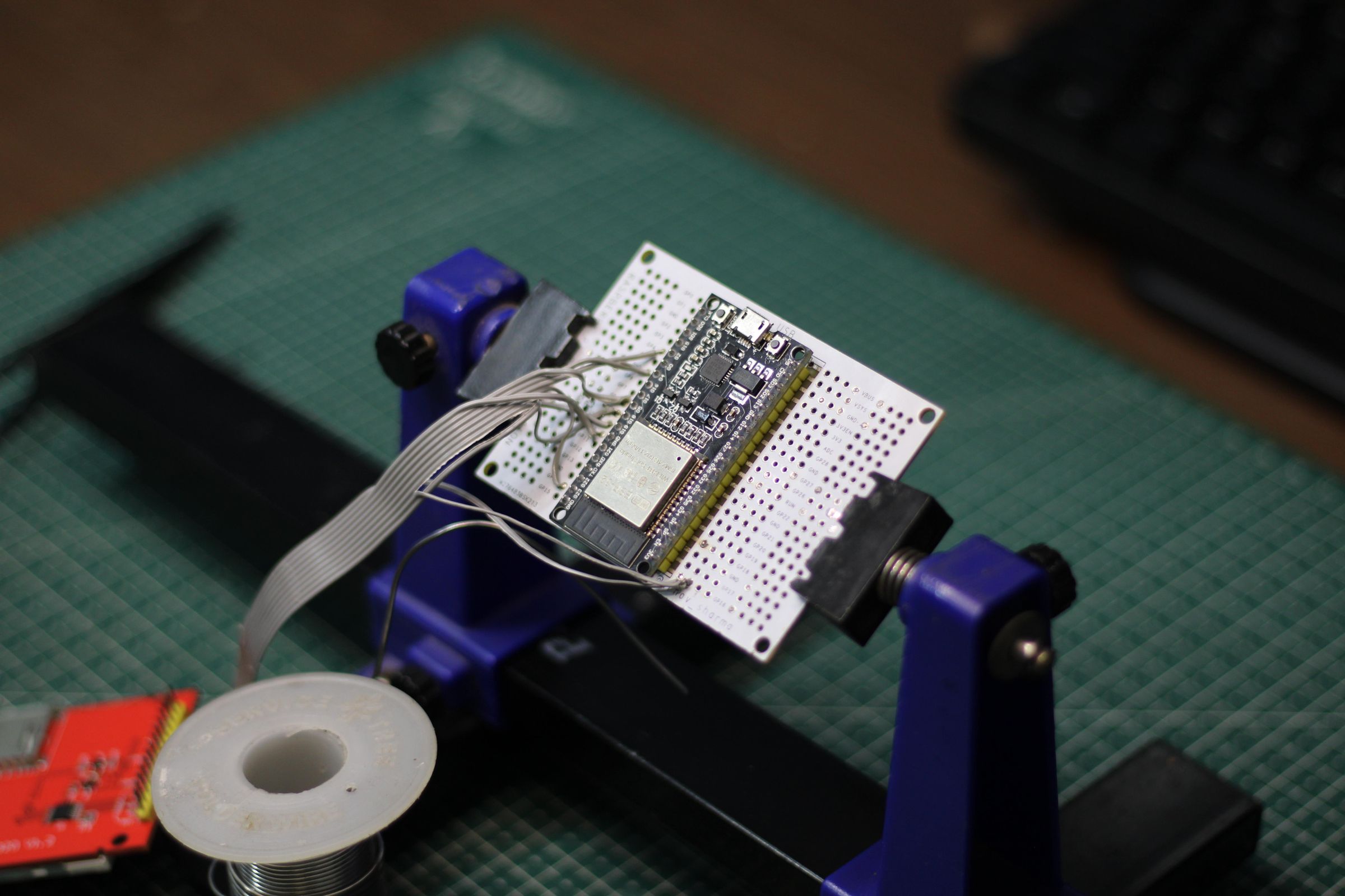
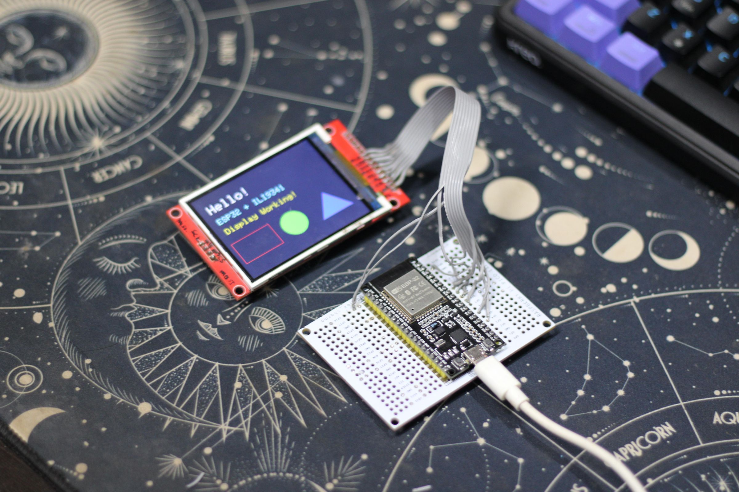
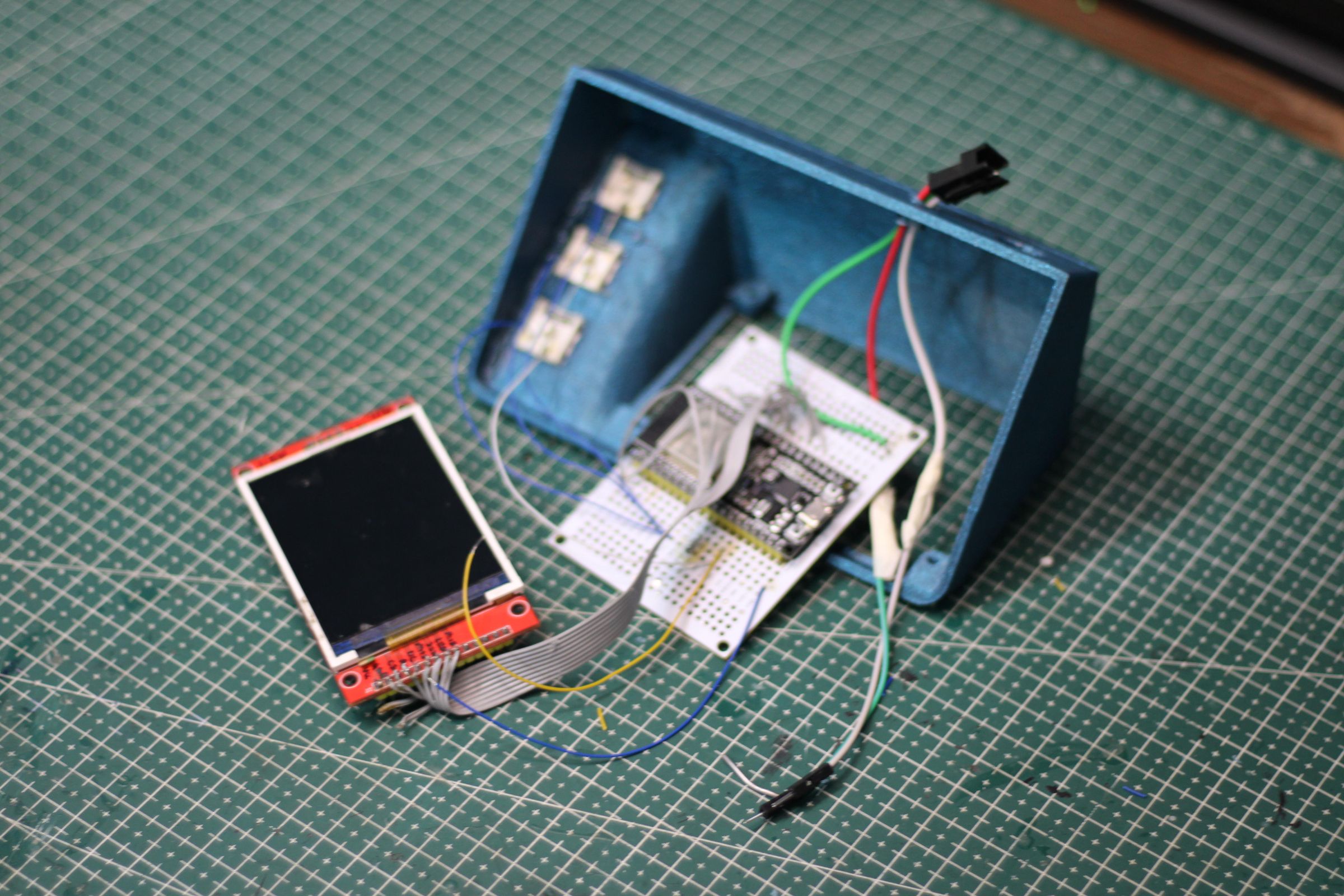
The electronics side is built around an ESP32, a buck converter to bring 12V down to a safe 5V for the strip and controller, a logic level shifter for the LED data line, a 320x240 SPI TFT, and three mechanical switches for input. Nothing exotic, but a few of the connections matter more than they look like they should.
1. Power
A HW-688 buck converter takes 12–24V input and steps it down to 5.2V, rated up to 6A — enough to run the ESP32 and the LED strip off the same rail:
- HW-688 5V OUT + → LED strip 5V, and ESP32 5V/VIN
- HW-688 5V OUT − → LED strip GND, ESP32 GND, TFT GND, and all three switch GNDs — one shared ground point
Using the screw terminals rather than the module's USB output matters here, since the USB port is only meant for phone charging current, not the strip's full draw.
Sharing one common ground between every part of the circuit is the single most important wiring detail in the whole build — without it, the LED data line and the TFT's SPI communication both become unreliable in ways that are hard to trace back to "missing ground" if you don't already know to check for it.
2. ESP32 to LED Strip
The ESP32 outputs 3.3V logic, but WS2812B strips expect closer to 5V on the data line. A 74AHCT125 level shifter sits between them to bring the signal up to a level the strip reads reliably:
- ESP32 GPIO 27 → level shifter IN
3. ESP32 to Display
The display communicates over SPI:
- VCC → 3.3V
- GND → GND
- CS → GPIO 5
- RESET → GPIO 4
- DC → GPIO 2
- MOSI → GPIO 23
- MISO → GPIO 19
- SCK → GPIO 18
- LED → 3.3V
Left the backlight pin wired straight to 3.3V rather than a GPIO, since dimming the screen backlight wasn't something this build needed — though it's an easy thing to add later if wanted, just by moving that wire to a spare GPIO and PWM-ing it.
4. ESP32 to Switches
Three mechanical switches, each wired between a GPIO and ground, using the ESP32's internal pull-up resistors rather than external ones:
- NEXT → GPIO 32
- SELECT → GPIO 33
- BACK → GPIO 25
With INPUT_PULLUP, each pin reads HIGH normally and drops to LOW the instant the switch is pressed — no external resistors needed, just a wire from the GPIO to one leg of the switch and another wire from the other leg to ground.
These three GPIOs weren't picked at random — 32, 33, and 25 avoid the ESP32's strapping pins (0, 12, 15), which affect boot behaviour if they're pulled low at power-up. Wiring a switch to one of those by accident can stop the board from booting at all if it happens to be held down during power-on.
5. Noise Suppression (optional)
Two small capacitors ended up making a real difference once everything was running together:
- a 1000µF electrolytic capacitor across the strip's 5V/GND, right at the strip's power input — absorbs the current surge when the strip switches from dark to bright, instead of letting it sag the whole shared rail
- a 100nF ceramic capacitor across the TFT's VCC/GND, right at the display module — filters high-frequency noise that would otherwise occasionally show up as a corrupted frame on the screen right as the LEDs changed brightness
Neither is strictly required for the circuit to function, but both noticeably improved reliability once the LED strip, the display, and WiFi were all active at the same time.
6. Bringing It All Together
With everything wired, the boot sequence looks like this: the ESP32 initialises the display first, then the LED strip (kept off, no current draw yet), then connects to WiFi, then starts the WebSocket server. Keeping that order — display before strip, strip before WiFi — turned out to matter for avoiding a display glitch that showed up early on, covered in more detail in the debugging step.
Final Assembly
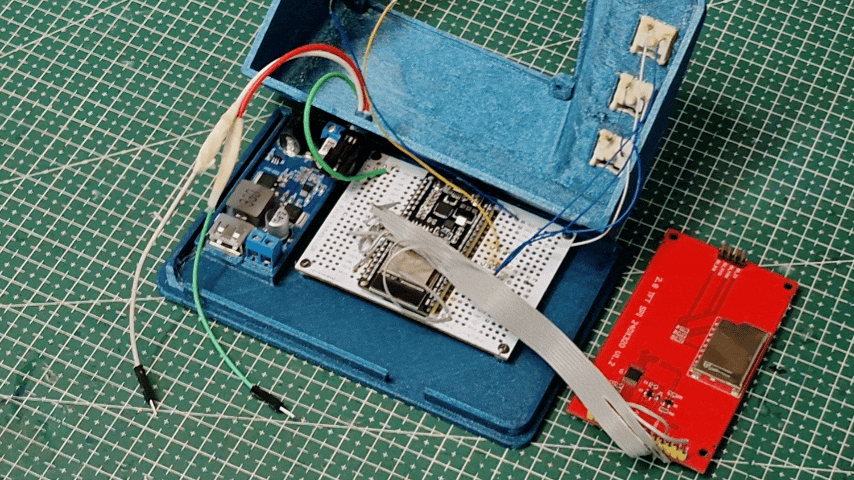
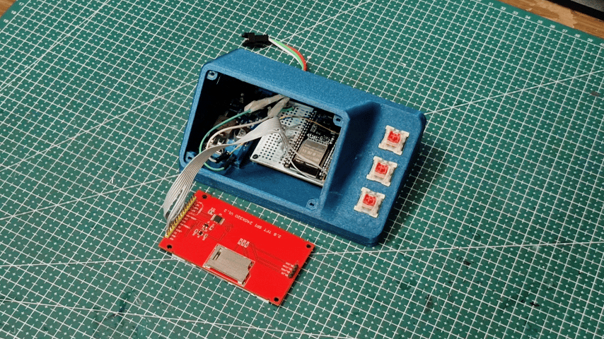
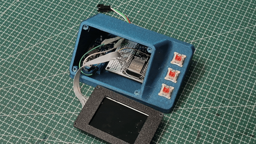
With all the individual components tested, it was finally time to assemble everything inside the enclosure.
I first secured the TFT display onto the display mounting plate, followed by the mechanical switches and the ESP32. After routing the wiring neatly inside the enclosure, I connected the remaining components and performed one final check to ensure everything was working as expected.
Once the enclosure was closed, PrismCast was finally beginning to look like a finished product rather than a collection of individual parts.
With the hardware complete, the next step was bringing it to life by writing the firmware that powers the display, controls the LEDs, handles user input, and communicates with the web dashboard.
Images to Include
- Components mounted inside the enclosure
- Internal wiring
- Enclosure before closing
- Fully assembled controller
Testing the Hardware
Before moving on to the final firmware, I wrote a simple hardware test sketch to verify that all the components were working correctly.
The test program checked the basic functionality of the TFT display, mechanical switches, WS2812B LED strip, and Wi-Fi, making sure each module was functioning as expected before integrating everything into the main firmware.
This simple step helped me catch any wiring or hardware issues early, making the rest of the development process much smoother.
Images to Include
- Hardware test running
- TFT display test
- LED test
- Button test
Developing the Software
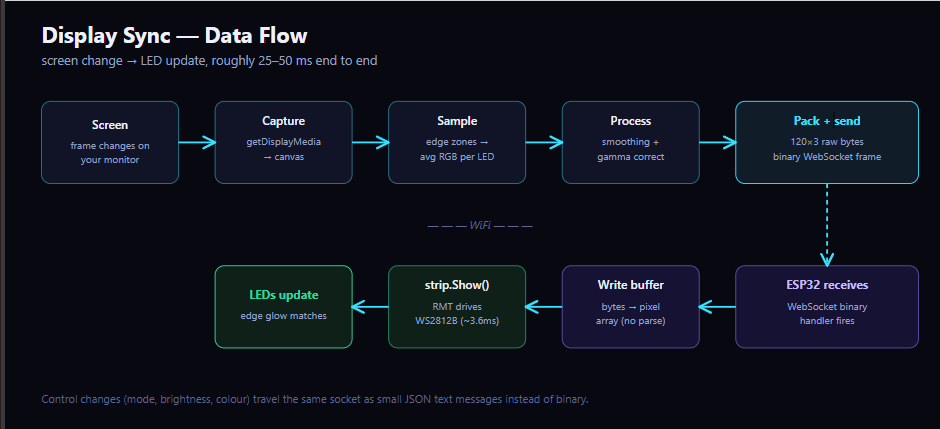
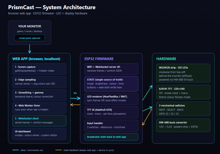
PrismCast uses a split architecture — it's a laptop and an ESP32 talking to each other, each handling the part it's better suited for.
The basic idea was:
Browser = Processing ESP32 = Display + LEDs Splitting it this way meant I could build and test almost the entire control interface before the hardware even existed, and debug the two sides independently instead of one giant tangled sketch.
System Architecture:
The software is divided into two main parts:
Web App (Browser)
The web app runs locally in the browser and handles:
screen capture colour sampling the whole control dashboard WebSocket communication It's built using plain HTML, CSS, and JavaScript — no frameworks, no build step, just files you can open in a browser.
For the live "ambilight" feature, the browser's own getDisplayMedia() API grabs the screen directly, so there's no separate capture software needed.
Once sync is turned on, the web app continuously streams live LED colours to the ESP32 over WebSocket.
ESP32 Firmware
The ESP32 focuses on:
LED rendering TFT display rendering WebSocket communication button input keeping local time The firmware was written using the Arduino framework along with NeoPixelBus (for the LED strip) and Adafruit GFX / Adafruit ILI9341 (for the display).
Instead of doing any colour processing itself, the ESP32 mostly just receives already-processed pixel data and pushes it straight to the strip. All the actual thinking (screen capture, sampling, smoothing) happens on the browser side.
In the next steps I'll go through the important parts of the code one by one — the device UI first, then the firmware, then the web app, then how the two actually talk to each other.
Designing the Device UI
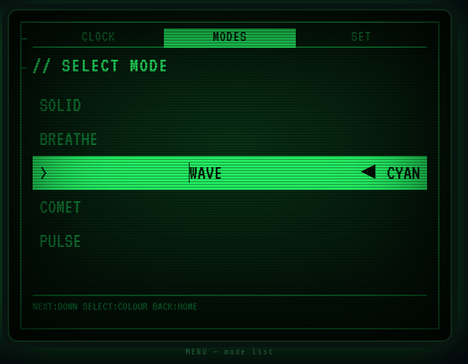
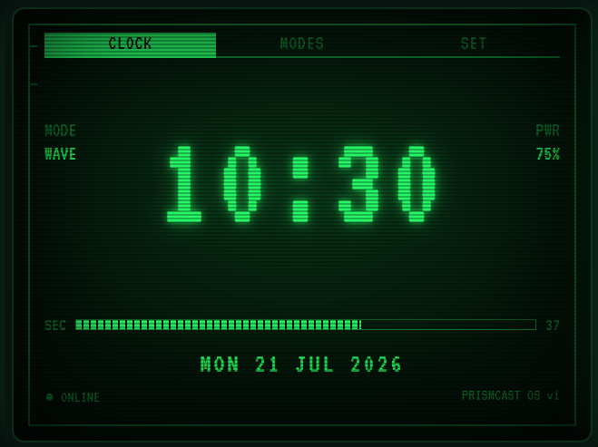
I designed PrismCast's screen in Lopaka. I started by creating a new project and selecting the 320x240 ILI9341 display configuration along with the Adafruit GFX / Adafruit ILI9341 graphics library, so the exported code would line up directly with the ESP32 firmware setup.
The display is a 320x240 SPI TFT, which is small enough that the interface has to stay legible at a glance — no clutter, no tiny text, just the essentials readable from across a desk.
Instead of a bright, app-style interface, I went with a monochrome, glowing terminal look — closer to an old CRT display than a phone screen. The twist is that the "monochrome" colour isn't fixed. It follows whichever LED mode is currently active, so the screen and the LED strip always visually agree:
cpp
Solid mode glows cyan. Wave mode glows green. Comet glows orange. Every drawing function just asks themeColor() for its colour, so there's no theme system to maintain — one function, always the right answer.
I created separate screens for:
- Home — the clock (default view)
- Menu — mode picker
- Set Time — adjusting the clock
Since this is meant to work as a desk clock first and an LED controller second, the clock had to be the default screen, not something buried behind a menu.
The HUD Frame
Every screen shares the same border — a double-line rectangle with a notch cut into the left edge, plus a row of three tabs across the top (CLOCK / MODES / SET) with the active one highlighted:
cpp
dim565() takes any colour and returns a dimmed version of it — that's what gives the UI depth without needing a second accent colour. Bright theme colour for the important stuff, dimmed version of the same colour for borders and labels.
Hand-Drawn Seven-Segment Digits
The built-in font didn't look right for a clock, so I drew actual seven-segment digits instead — same encoding real digital displays use internally:
cpp
Each segment is a small hexagon rather than a plain rectangle (a bar with triangular end-caps), which reads a lot closer to a real digital display than a blocky rectangle would:
cpp
Unlit segments aren't fully black either — they're drawn dim, in the same theme colour, so there's a faint "ghost" outline behind the lit digits. Small detail, but it's what makes it look like a real display instead of text on a screen.
Keeping It Flicker-Free
Redrawing the whole screen every frame looks bad on a small SPI display — visible tearing, and it's slow. So most screens track what was last drawn and only repaint what actually changed:
cpp
Programming the ESP32
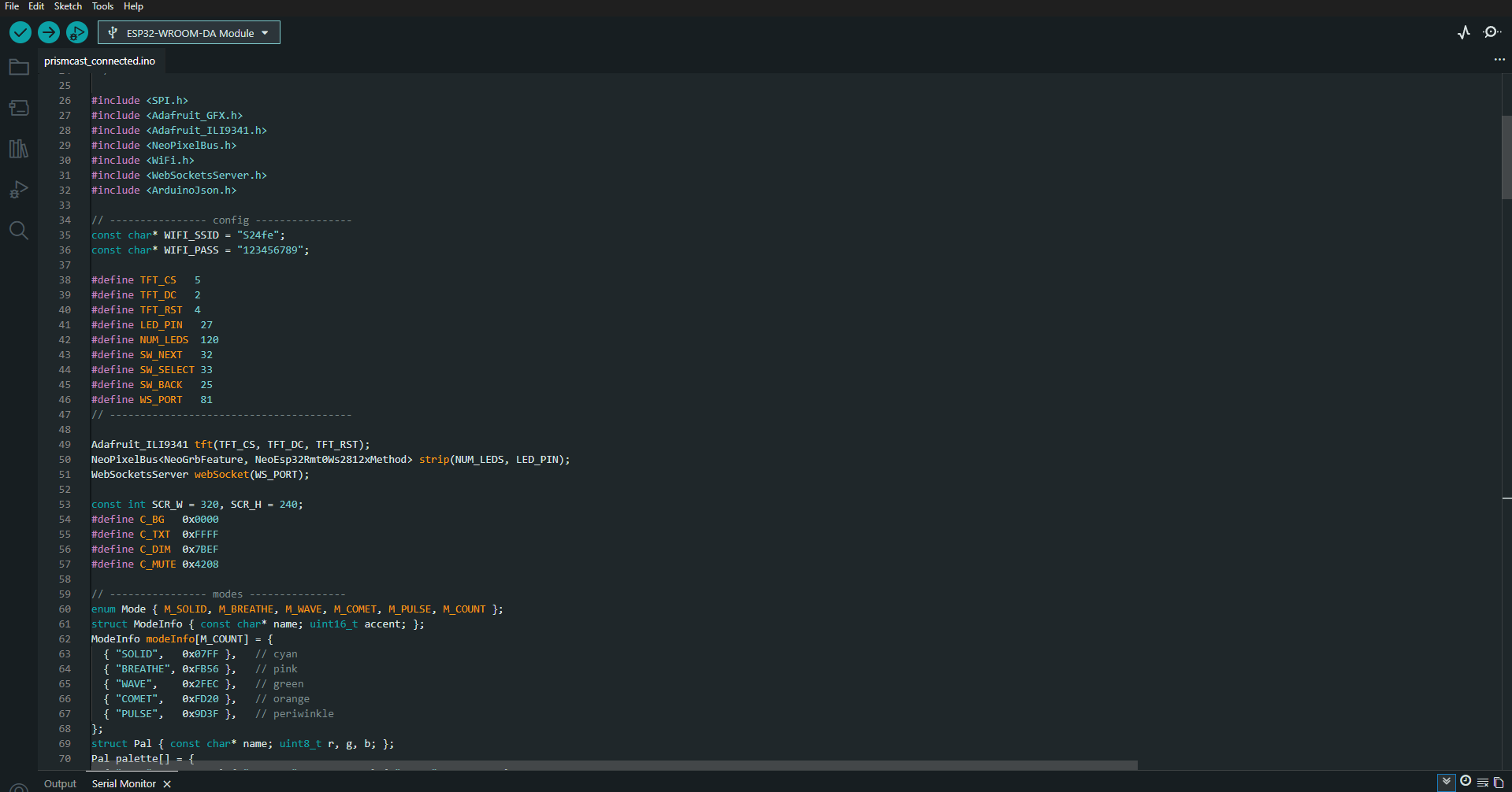
ESP32 Firmware & LED Logic
The ESP32 side of the project mainly handles:
- LED strip rendering
- display rendering
- WiFi communication
- WebSocket communication
- button input
- keeping local time
The firmware was written using:
- NeoPixelBus
- Adafruit GFX
- Adafruit ILI9341
- WiFi
- WebSocketsServer
- ArduinoJson
1. LED Strip Configuration
The strip uses NeoPixelBus running on the ESP32's RMT peripheral, which is hardware-timed and doesn't glitch when WiFi is active in the background — a plain bit-banged library can stutter under WiFi interrupts, RMT doesn't:
Inside setup(), the strip is initialised and cleared before anything else touches it:
2. State-Based Mode System
Instead of scattering mode logic everywhere, every LED mode lives in one function that switches on the current global mode:
Example — the Wave mode, a rainbow that flows around the strip over time:
The device also has a Sync state that isn't a local mode at all — while the web app is streaming, incoming pixel data drives the strip directly and local rendering is skipped until the stream stops.
3. Display Configuration
The screen uses SPI communication with the following pins:
The display object is initialised using:
Inside setup():
I deliberately call tft.begin() with no explicit SPI speed argument — forcing a custom clock caused the display to glitch when WiFi came up, so leaving it at the library default turned out to be the fix.
4. WiFi Communication
The ESP32 connects to a normal WiFi network (in my case, a phone hotspot):
Connection logic:
WiFi.setSleep(false) turned out to matter more than expected — with it left on, the ESP32's WiFi radio would sleep between beacons to save power, and the WebSocket handshake couldn't complete fast enough. Pings still worked (delayed), but the WebSocket itself failed. Disabling sleep fixed it completely.
Once connected, the IP is printed to Serial and shown on the screen so it's easy to plug into the web app:
5. WebSocket Communication
A WebSocket server is started on port 81:
The web app connects directly to the ESP32 using this IP, and both sides use it for two different kinds of traffic — pixel data going one way, control messages going both ways.
The ESP32 keeps listening for incoming data using:
inside the main loop.
6. Receiving Sync Frames
When the web app is running Display Sync, it streams raw binary pixel data — three bytes per LED, no JSON, no parsing:
If no binary frame arrives for about 600ms (say, sync was stopped, or the browser tab was closed), the firmware automatically falls back to whatever local mode was active before:
7. Receiving Control Messages
Mode changes, brightness, and colour come in as small JSON text messages instead, parsed with ArduinoJson:
Splitting traffic this way — binary for the high-frequency pixel stream, text for the occasional control change — keeps both fast where it matters and readable where it doesn't.
8. Single Source of Truth
Both the physical buttons and the web app write into the same set of global variables (gMode, gBrightness, gR/gG/gB). Whenever either side changes something, the firmware broadcasts the new state back out over WebSocket, so the two stay in sync automatically:
Change the mode from a button, the web page updates. Change it from the web page, the device updates. Neither side has to poll the other.
9. Button Input
Three mechanical switches — NEXT, SELECT, BACK — each wired to a GPIO with INPUT_PULLUP, so no external resistors are needed. Every button supports both a short click and a long hold:
NEXT opens the mode menu, SELECT cycles brightness (or colour, depending on the screen), and BACK moves between screens.
10. Local Clock
Rather than depending on WiFi/NTP for the clock to work at all, PrismCast keeps its own time using millis() as a running offset from a base timestamp:
The time is set once through the SET screen and just keeps counting from there — the clock works fine even if WiFi never connects.
11. Debugging & Development
Most of the debugging during firmware development came down to:
- SPI display glitches when other things ran at the same time
- WebSocket library incompatibility with newer ESP32 cores
- WiFi power-saving silently breaking the WebSocket handshake
- LED/TFT SPI contention causing the LEDs to stop responding
Serial logging was used heavily throughout:
This made it much easier to tell whether pixel frames were actually arriving versus the strip just not lighting up for some other reason.
Building the Web App
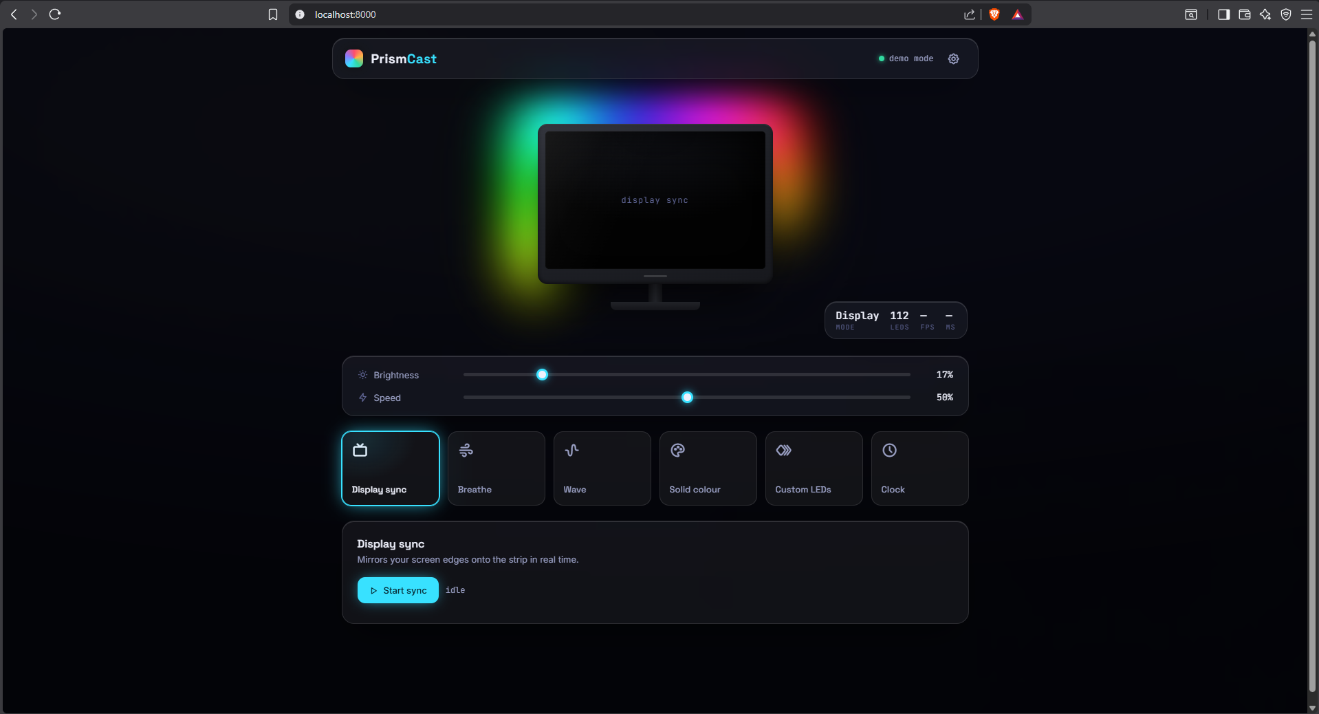
The web app is the main processing side of the project. It handles:
- screen capture
- colour sampling
- the control dashboard (modes, colours, presets)
- communication with the ESP32
Built using:
- HTML
- CSS
- JavaScript (plain, no framework, no build step)
and runs directly in the browser on the same computer as the monitor being synced.
1. Connecting to the ESP32
The device's IP is entered directly in the app's settings panel and stored in state:
The browser then connects to the ESP32 using a WebSocket:
2. WebSocket Error Handling
To make connection issues easier to debug, I added logging directly to every stage of the connection:
This made it much easier to tell apart a few different failure modes while testing — wrong IP, device offline, or the device reachable by ping but not accepting WebSocket connections (which turned out to be a WiFi power-saving issue on the ESP32 side, not the browser).
3. Screen Capture
Display sync starts by asking the browser for a live screen feed:
This only works from localhost or https — a page opened directly as a file can't call it — so the app has to be served with a local server instead of just double-clicked open.
The stream gets attached to a hidden <video> element, and each tick draws the current frame onto a small offscreen canvas:
4. Edge Sampling
Instead of processing the whole screen, the app only samples thin strips along each edge — one small region per LED. Each LED's zone position is calculated automatically from the monitor size and how many sides are covered:
Each zone is averaged into a single colour by sampling every few pixels rather than every single one — visually identical, much faster:
5. Smoothing and Gamma Correction
Raw sampled colours flicker on fast-moving content, so each LED's colour is blended with its previous value instead of jumping straight to the new one:
Gamma correction is applied before that, so the LEDs' brightness curve matches what the eye actually sees on screen rather than a straight linear mapping:
6. Sending Data to the ESP32
Once a frame's colours are ready, they're packed into a compact binary buffer — three bytes per LED, nothing else — and sent as a single WebSocket message:
Control changes (switching modes, adjusting brightness, picking a colour) go out separately as small JSON messages instead:
7. Keeping Sync Running in the Background
The biggest surprise during testing: sync would work perfectly while the browser tab was focused, then stop the moment I switched to a fullscreen game. Browsers heavily throttle requestAnimationFrame (and even setInterval) in hidden tabs to save battery — exactly the situation PrismCast needs to work in.
The fix was moving the capture loop into a Web Worker, since worker timers aren't throttled the same way:
Every tick from the worker triggers one capture-sample-send cycle, and this keeps running at full rate even with the tab completely hidden behind a fullscreen game.
8. Not Overloading the ESP32
Early on, toggling sync on and off a few times in a row made the strip get noticeably warm and eventually stop responding. The cause turned out to be a leftover capture loop that never got shut down properly — starting sync again just piled another one on top, so the device ended up receiving two or three times as many frames per second as intended.
Two fixes: a proper teardown function that's called both when sync stops and right before it starts again, so there's never more than one active loop —
— and a backpressure check before sending each frame, so a slow WiFi connection makes the app skip a frame instead of queueing more on top:
9. Colour Wheel and Custom Editor
Outside of sync, the dashboard has a full HSV colour wheel for solid colours, and a per-LED custom editor where the strip is laid out on screen in the actual shape of the monitor (top row, side columns, bottom row) instead of a flat line — clicking or dragging paints each LED directly:
- The complete web app source is attached separately in the project files.
How Display Sync Works
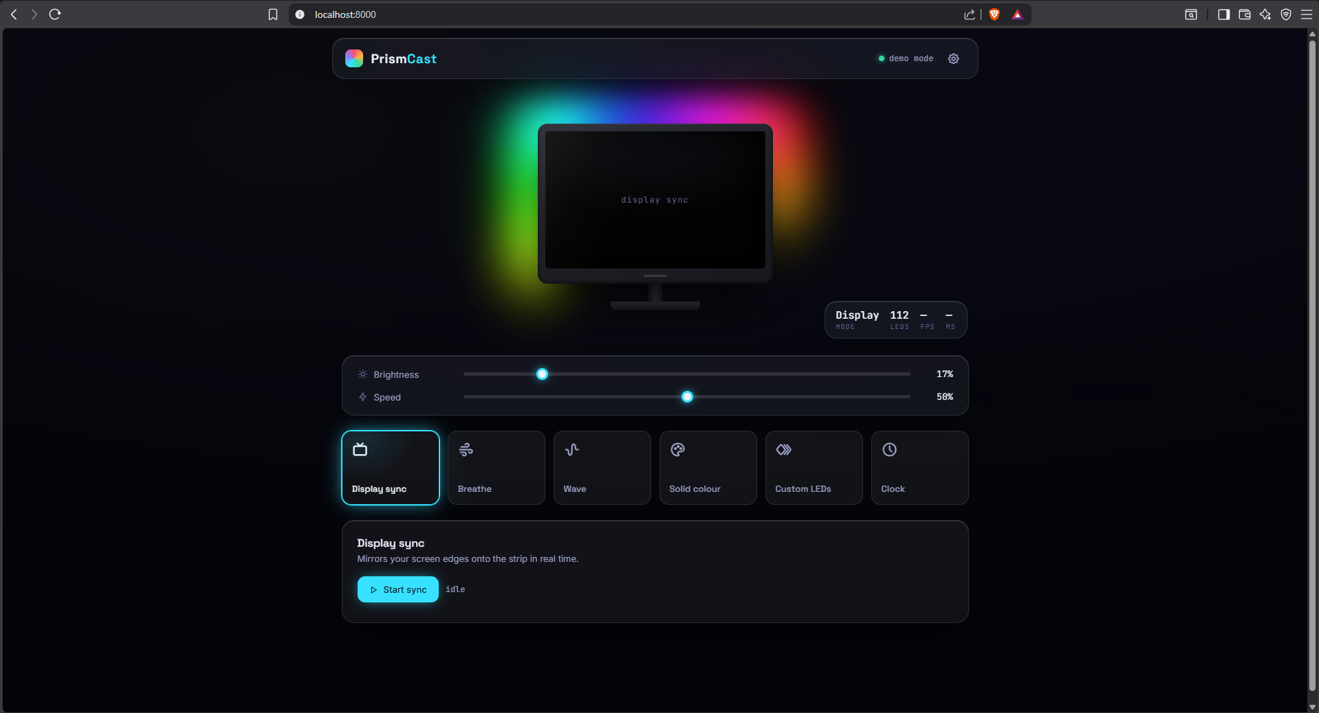
This is the feature the whole project is really built around, so it gets its own step. The idea is simple to describe — the LED strip mirrors whatever's on the monitor — but getting it to feel instant, and getting it to keep working while a fullscreen game is running, took a few rounds of fixing.
Overview:
Display sync involves both halves of the project working together continuously, roughly 20 times a second:
- the web app captures the screen and works out a colour for each LED
- that colour data gets sent over WebSocket
- the ESP32 receives it and pushes it straight to the strip
None of this uses any separate capture software — it's all done with the browser's own APIs.
1. Capturing the Screen
The browser has a built-in API for grabbing a live feed of the screen, getDisplayMedia():
This only works from a secure context — localhost or https — so the web app has to be run through a local server rather than opened directly as a file. The returned stream gets attached to a hidden <video> element, and each capture tick draws the current frame onto a small offscreen canvas.
2. Sampling the Edges
Instead of processing the whole screen, only thin strips along each edge get sampled — one small region per LED. These regions are generated automatically based on the monitor size and how many sides are covered, rather than being placed by hand:
Each zone gets averaged down to one colour by sampling every few pixels instead of every single one:
3. Smoothing and Gamma Correction
Raw sampled colours flicker badly on fast-moving content, so every LED's colour is blended toward its new value instead of jumping straight to it:
Gamma correction runs before that, so the LEDs' apparent brightness matches what's actually on screen instead of a flat linear mapping:
r = Math.pow(r / 255, GAMMA) * 255;
4. Packing and Sending
Once a frame's 120 colours are ready, they get packed into a small binary buffer — three bytes per LED, nothing else — and sent as one WebSocket message:
Binary instead of JSON here matters — at 20 frames a second, a text format would mean extra parsing work on the ESP32 side for no benefit. Raw bytes go straight from the network buffer into the LED buffer.
5. Receiving on the ESP32
On the firmware side, incoming binary WebSocket frames are handled directly, with no JSON involved:
If frames stop arriving for about 600ms, the firmware assumes sync has stopped and falls back automatically to whatever local mode was running before — no manual switch needed on either side.
6. The Latency
Screen change to LED update ends up somewhere around 25–50ms on a normal WiFi connection:
- capture pipeline: roughly 8–16ms
- sampling in JS: 1–3ms
- WiFi transit: 5–15ms
- ESP32 processing: under 1ms
- pushing data to the strip: about 3.6ms
That's well under the point where a delay becomes noticeable — for reference, commercial ambilight-style TVs run in roughly this same range.
7. Keeping It Running Behind a Fullscreen Game
The one thing that didn't work at first: sync ran fine while the browser tab was visible, then stopped completely the moment a fullscreen game took focus. Browsers throttle requestAnimationFrame — and even plain setInterval — down to about 1fps in fully hidden tabs to save power, which is exactly the situation this feature needs to survive.
The fix was moving the capture loop into a Web Worker, since worker timers keep running at full speed even when the tab is hidden:
Every tick from the worker runs one capture-sample-send cycle, regardless of whether the tab is focused, visible, or sitting behind a fullscreen window.
8. Not Flooding the ESP32
Toggling sync on and off a few times during testing made the strip get noticeably warm, and it eventually stopped responding altogether. The cause was a capture loop that never actually shut down — starting sync again just stacked a second one on top of the first, so the device ended up getting two or three times the intended frame rate.
Fixed with a proper teardown that's called both when sync stops and right before it starts again, so there's never more than one loop running:
Plus a small backpressure check before every send — if the WebSocket hasn't finished flushing the last couple of frames, the new one gets dropped instead of queued:
The frame rate also got knocked down from 30fps to 20fps, which is still smooth for ambient lighting and noticeably kinder to both the WiFi link and the ESP32.
9. Matching the Physical Wiring
One last detail: the web app's sample order and the strip's actual physical order have to agree, or the colours land on the wrong edges entirely — a light that's supposed to be top-right shows up bottom-left, moving the wrong way round.
Rather than hardcoding one direction, there's a small calibration block at the top of the state file:
Problems Faced & Debugging
A good chunk of this project was just debugging one thing after another until the whole system finally behaved. Since it touches firmware, networking, browser APIs, and live LED timing all at once, quite a few things broke along the way.
1. WebSocket Library Wouldn't Compile
The first WebSocket library I tried (an ESPAsyncWebServer fork) failed to compile on the current ESP32 core with errors like:
That function was renamed in newer mbedtls versions, and the older library fork never got updated for it. Rather than fight version mismatches, I switched to the WebSockets library by Markus Sattler (Links2004) — a synchronous library with no AsyncTCP dependency, so the whole mbedtls conflict disappeared:
cpp
2. The Display Would Glitch White
At one point, adding WiFi and WebSocket code to the firmware made the TFT go white mid-boot, right around when the LED strip first lit up. It looked like a straightforward power issue at first, but disconnecting the strip entirely didn't fix it — the display still glitched.
The actual cause turned out to be a mix of things:
- calling tft.begin() with a forced custom SPI speed instead of the library default
- blocking for several seconds on NTP time sync inside setup()
- LED and TFT updates happening back-to-back in the same loop iteration, letting electrical noise from one interfere with the other
cpp
Removing the forced SPI speed, making NTP sync non-blocking, and giving LED updates and screen draws their own separate timers fixed it completely.
3. WiFi Connected but WebSocket Wouldn't
A stranger one — ping to the ESP32 worked fine, but the browser's WebSocket connection kept failing with a 1006 error (handshake never completed). Ping times were also unusually high, sitting around 130ms instead of the usual 1–5ms on a local network.
That high ping was the actual clue. The ESP32's WiFi radio was going to sleep between beacon intervals to save power, so it wasn't awake in time to complete the WebSocket handshake — pings still got answered eventually, but the time-sensitive TCP handshake timed out. One line fixed it:
cpp
Ping times dropped to single digits right after, and the WebSocket connected immediately.
4. Sync Worked, Then Didn't, Then Worked Again
Display sync would run for a while, then silently stop, then sometimes start working again after a refresh — with no obvious pattern. Tracing it down, the capture loop was referencing a variable that was never declared, which threw a silent error the moment sync started. The app looked like it was syncing (the flag flipped to true), but no frames were ever actually being generated.
js
It "worked once" earlier only because an older cached version of the file was still loaded in the browser. Declaring the variable properly, and adding a try/catch around the capture tick so failures show up in the console instead of failing silently, fixed it for good.
5. The ESP32 Getting Hot and Locking Up
Toggling sync on and off a few times during testing made the LED strip noticeably warm, and eventually the whole device would stop responding. The cause was a capture loop that never actually got shut down — every time sync restarted, a new loop stacked on top of the old one instead of replacing it, so after a few toggles the device was receiving two or three times the intended frame rate.
Fixed with a proper teardown function called both on stop and right before every start, so there's never more than one loop running, plus dropping the frame rate from 30fps to 20fps and adding a backpressure check so a slow connection skips a frame instead of piling more on top of it.
6. LED Colours Landing on the Wrong Side of the Monitor
Once sync was reliably running, the colours didn't line up with the right edges — a light meant for the top-right corner would show up diagonally opposite, moving the wrong direction. The web app's internal sample order (which edge/corner it assumes the strip starts from) didn't match how the strip was actually soldered and mounted.
Rather than hardcoding a fixed direction, I added a small calibration block instead of trying to guess the wiring in code:
js
Tuned once by comparing where a light actually showed up against where it should have, and the whole strip lined up correctly.
7. Multiple Sketches in One Folder
A simpler one, but it cost some time — the Arduino IDE compiles every .ino file sitting in the same folder as one combined program. Having a leftover test sketch and an old copy sitting in the same folder as the main firmware caused a wall of "redefinition of X" errors that looked far scarier than the actual problem.
The fix is just discipline: one sketch per folder, folder name matching the .ino filename, nothing else dropped in alongside it.
8. Debugging Approach
Serial logging ended up being the most useful tool throughout, especially for anything network-related:
cpp
and on the browser side, console logging at every stage of the connection:
js
Between the two, it was almost always possible to tell whether a problem was on the browser side, the network, or the firmware — which mattered a lot given how many of these bugs looked identical from the outside ("nothing is happening") but had completely different causes underneath.
Final Testing & Integration
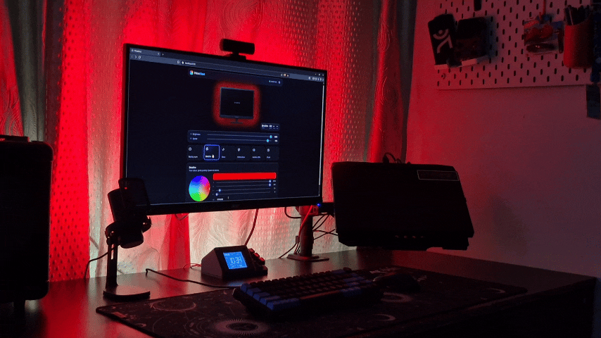
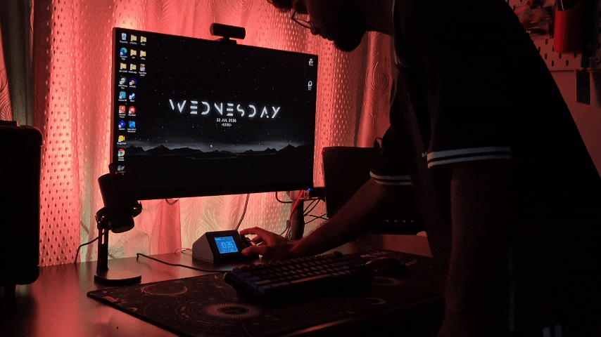
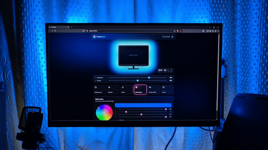
With the firmware complete, it was time to test the entire system as a whole.
I uploaded the final firmware to the ESP32 and verified every feature one last time, including the TFT interface, button navigation, lighting effects, clock, and communication with the browser dashboard. After confirming that everything was working correctly, I installed the controller beside my monitor and mounted the LED strip behind the display.
Watching the LEDs respond to the screen for the first time was one of the most satisfying moments of the project. After weeks of designing, printing, wiring, and programming, PrismCast had finally come to life.
Images to Include
- Firmware uploaded
- First successful boot
- Controller beside the monitor
- LEDs reacting to the screen
Final Results & Future Improvements
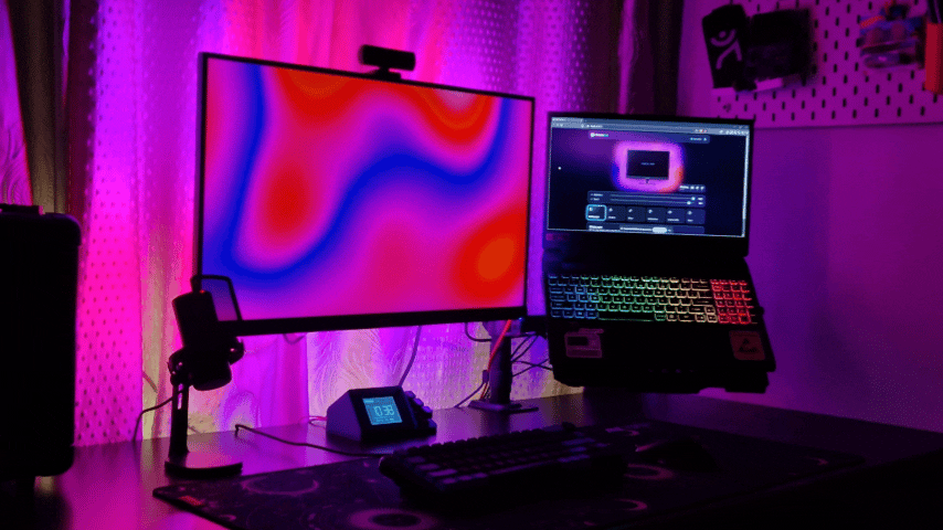
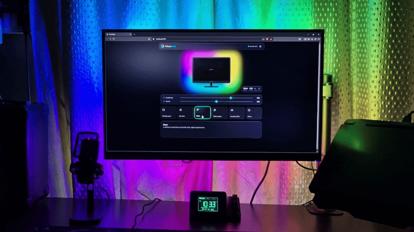
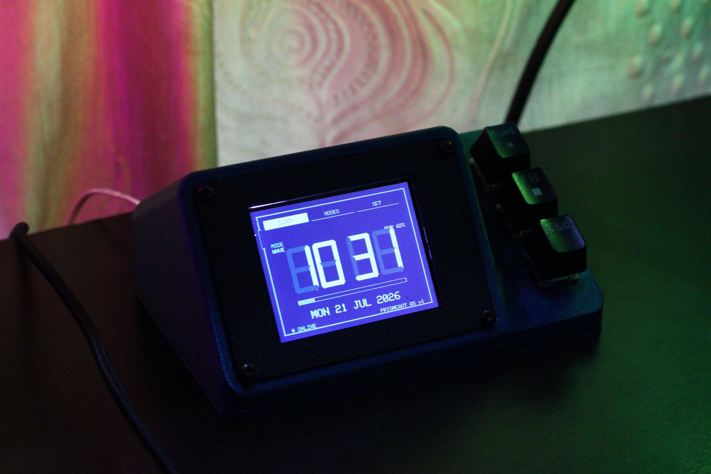
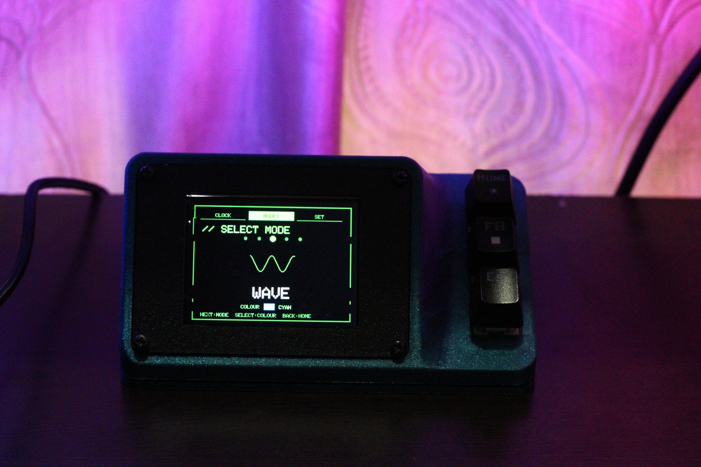
PrismCast started as a simple idea for a display-synchronized monitor backlight, but by the end of the project it had grown into something much bigger. What began as an RGB lighting project eventually became a complete desk companion with its own controller, custom firmware, browser dashboard, and user interface.
One of my favorite parts of the project is how it offers two completely different ways to interact with it. For everyday use, the physical controller makes it easy to change lighting modes, brightness, and colors with just a few button presses. Whenever I need more advanced customization, the browser dashboard provides complete control over the system, from display synchronization and per-LED editing to monitor layout configuration and presets.
Building everything from scratch was definitely the most challenging part of the project, but it was also the most rewarding. Instead of relying on existing firmware or software, every major part of PrismCast was designed specifically for this project, giving me complete control over both the hardware and software.
Like any project, there's always room for improvement. In the future, I'd love to design a custom PCB, add an RTC for more accurate timekeeping, include an ambient light sensor for automatic brightness adjustment, and introduce even more lighting effects and dashboard features.
I hope this project inspires you to build something of your own. If you enjoyed this Instructable or found it helpful, I'd really appreciate your vote in the Rainbow/RGB Contest. Feel free to leave a comment if you have any questions or suggestions.
Thanks for reading, and happy making!