Programmable RGB Flashlight for Light Painting
by dslrdiy in Circuits > Electronics
281 Views, 0 Favorites, 0 Comments
Programmable RGB Flashlight for Light Painting
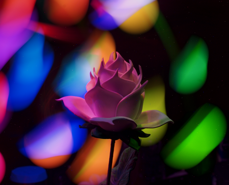
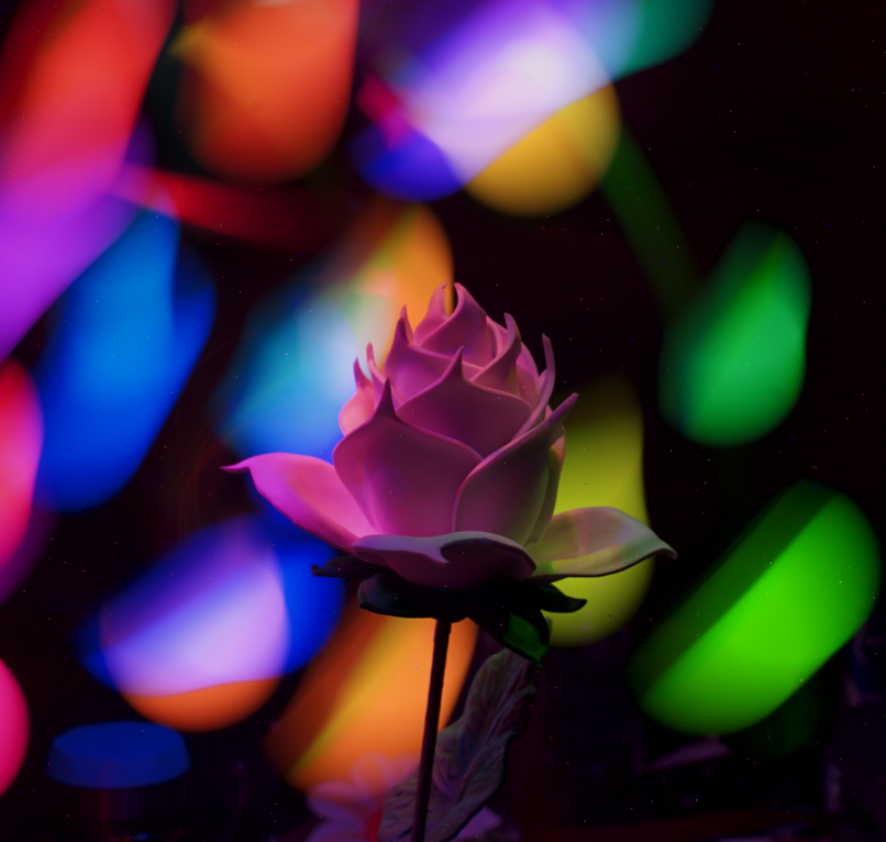

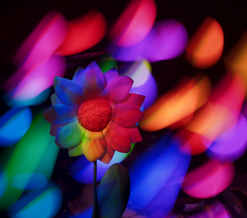

You can build your own programmable RGB flashlight and use it to create great light painting photos with all the colors of the rainbow. You just need some easy to get electronic parts. Using this kind of flashlight can create really great light patterns on objects or people (like portrait long exposure photos)
Supplies
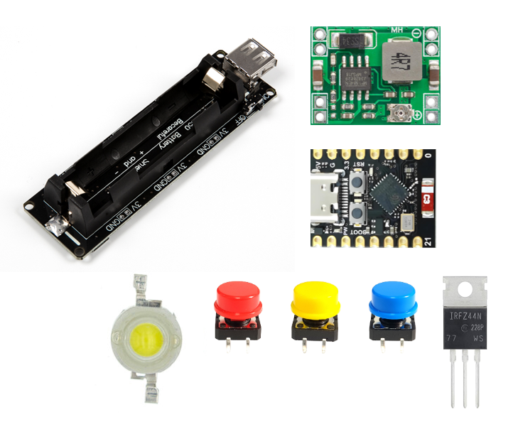
For this Programmable RGB flashlight you will need:
- mini ESP32-C3 (or an ESP32S3 super mini or ESP32C6 supermini)
- 3W RGB Leds or 10W RGB Led
- 18650 Battery Holder Board
- 18650 Battery
- MP1584 step down regulators
- 3 x IRFZ44
- 3 x buttons
- Rubber or isolator
- 3D Printed Case.
- Small Heatsink
- Heatsink glue
- Wires
- 3 x 10Kohm Resistors
Tools:
- Soldering Iron.
- Thin.
- pliers to hold cables.
- USB-A to USB-C cable or USB-A to micro USB cable.
- Laptop or PC
3D Printing the Case
Download the attached files and print them. This is really easy you only have to select the file into your slice software and print it.
Follow the link of my thingiverse: https://www.thingiverse.com/dslrcnc/designs
Programming the ESP32 C3
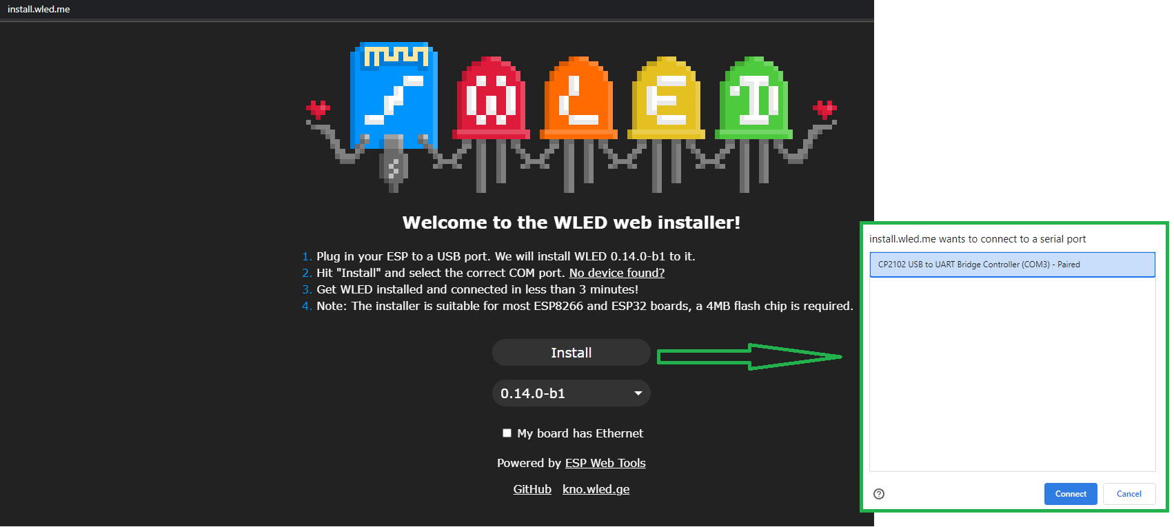
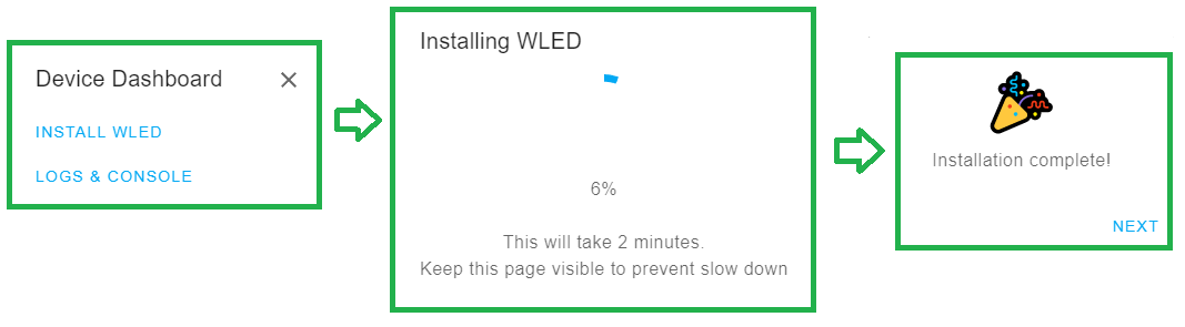
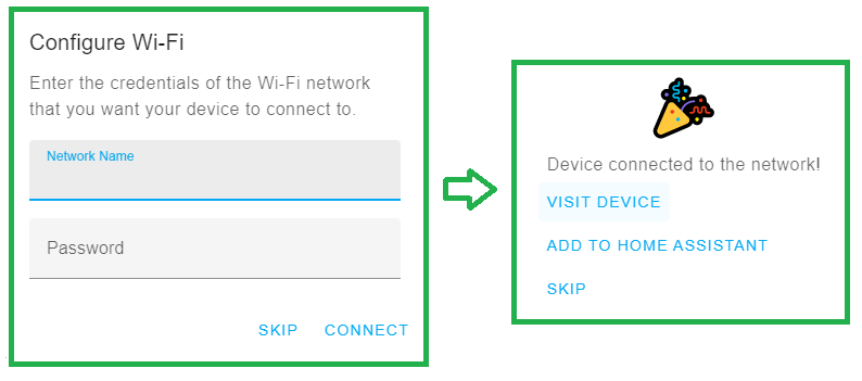
This is an easy step and quick step.
- Connect the ESP32 or ESP8266 to your computer using a micro USB to USB-A cable or the USB-C to USB-A cable, wait for the driver installation or download the drivers for your board if your computer doesn't recognize the drivers automatically:
- Go to the website: https://install.wled.me/ (this installation webpage will only work on Chrome)
- Click on Install.
- Select your USB Serial Port (COM_) and click Connect.
- Click on Install WLED and Confirm Install.
- Wait for a couple of minutes until the installation is complete.
- Click on NEXT once the installation is Complete.
- Enter your WIFI Network Name and Password so your ESP will easily connect.
- Click on VISIT DEVICE so the installation page will direct you to your new WLED device.
- Remember the IP address of your WLED. (Mine was 192.168.1.10).
- Configure the LEDs output in the LED Preferences menu and Enter 8, 9, 10 in the RGB pin configuration and Save!. (The number of the pins are the number of the pins that you soldered your cables, if you mixed the cables DON'T WORRY, you can change the pin number in order to turn on the correct RGB LED)
- DONE!.
Once you programmed your main board you can place all the pieces inside the 3d printed case and use some hot glue to lock the place.
If the main WLED webpage doesn't work you can try this website and find your board. https://wled-install.github.io/
Assembling the Pieces
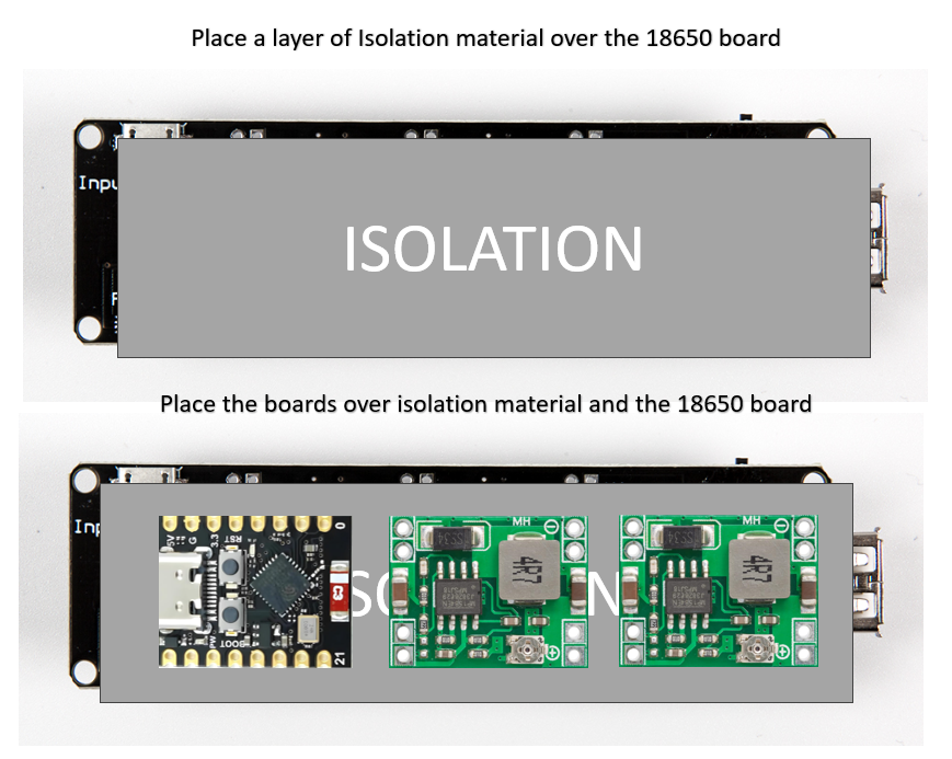
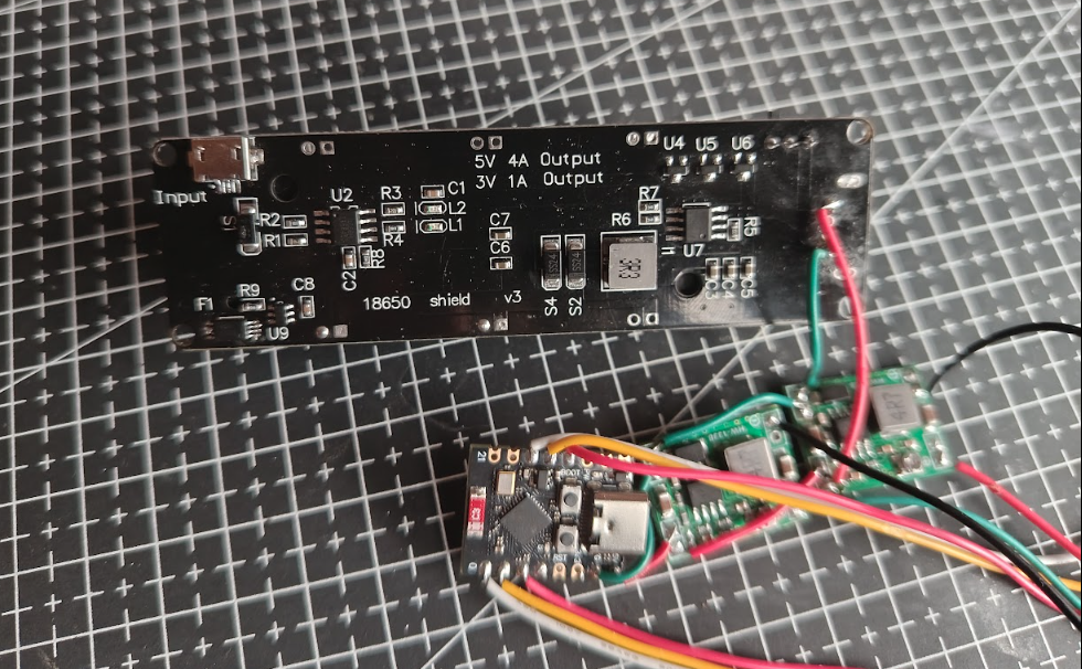
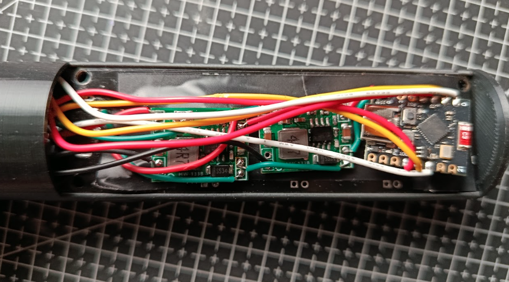
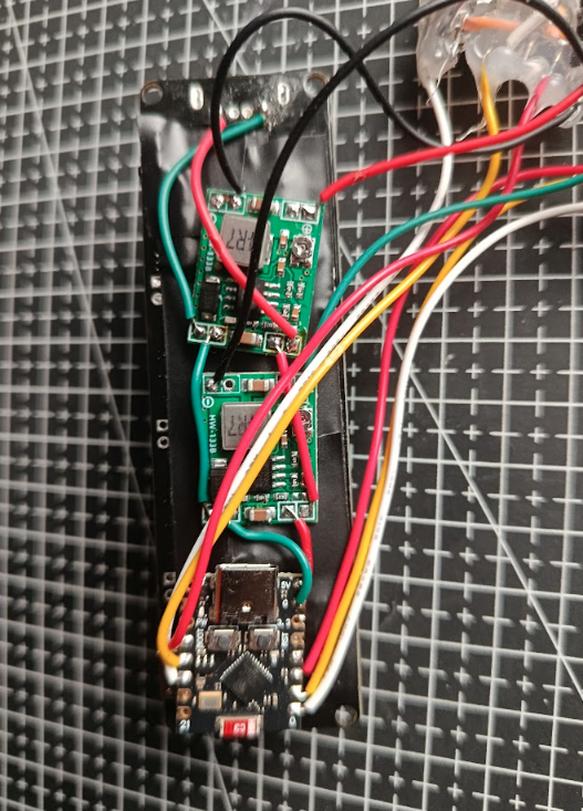
Glue or tape the isolator in the back of the 18650 battery holder board.
Glue the main esp32 board and the two regulator boards over the isolator.
Glue the Buttons over the 3d printed rail parts and glue them using hot glue or super glue.
Using the heatsink glue place the LEDs on the 3d Printed front part or just place the only LED on the front part
Soldering and Connecting
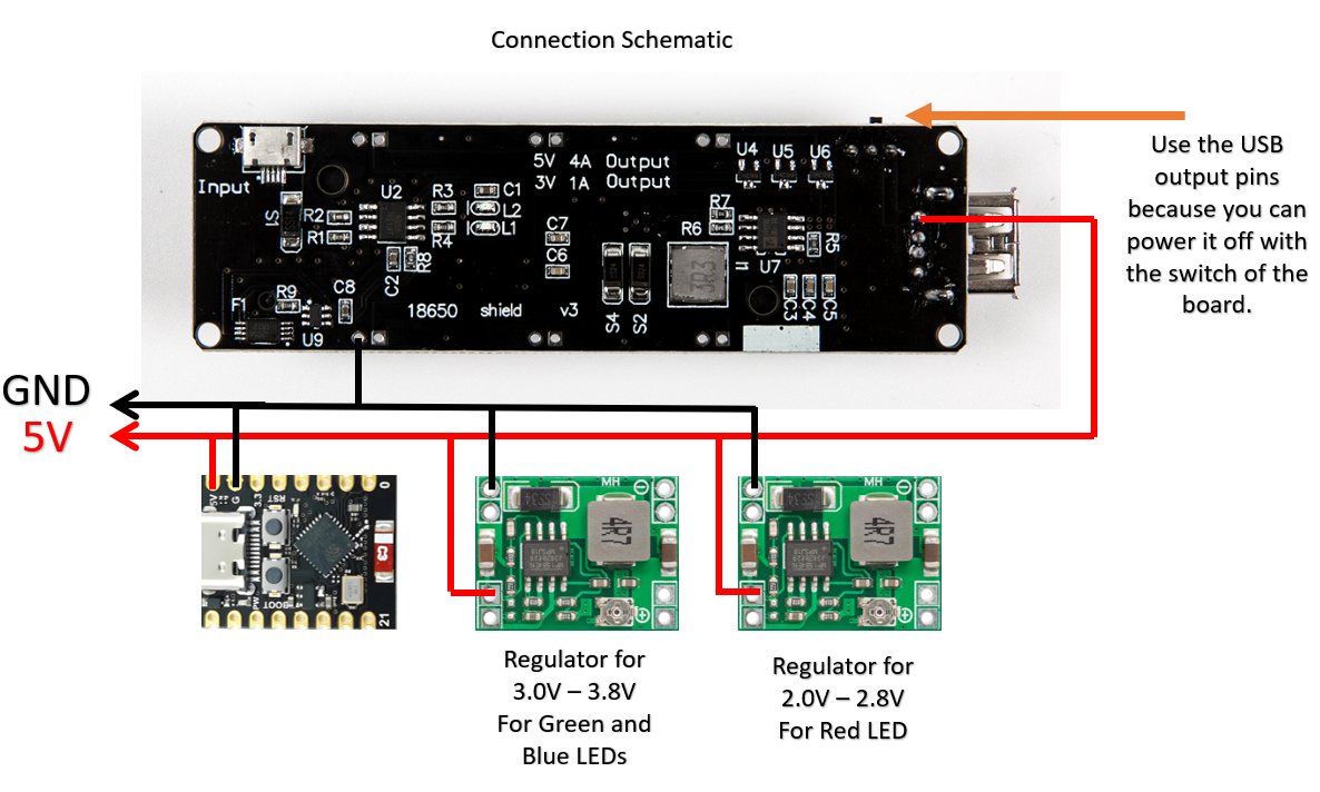
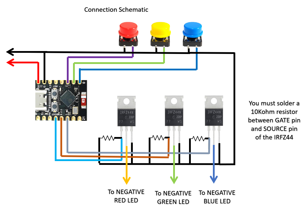
Once you place all the parts you can start soldering wires to connect the boards. Follow the diagram and connect the wires. Do not forget to use soldering paste or Flux to easily solder the wires to the pads of the boards.
First you will need to connect the 18650 battery board USB output pin to the 5V pin of the ESP32 Board and the positive pins of the regulator boards. And will do the same for the GND pin from the 18650 battery board to the ESP32 board and both regulator boards.
Then you will need to connect the IRFZ44 to control the 3W LEDs.
- Solder the 10Kohm resistor between the gate pin and the source pin of every mosfet.
- Solder all the source pins to an GND wire.
- Solder the gate pins to a pin of the esp32 board (you can use 8, 9 and 10 pins for this)
- Solder wires from the drain pin to the negative (cathode pin) of every LED.
Then solder one pin of every button to GND.
And solder the other pin of the button to a pin of the esp32 board. (you can use the 0, 1, and 2 pins)
Control Your Flashlight From Your Smartphone or Your Computer
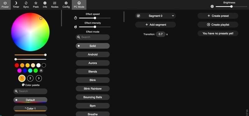
Something great about WLED and the ESP32 is that you can download the WLED app from the Play Store or the Apple store that will let you control your RGB flashlight from your smartphone and add some great effects and colors.
You can create sequences, use different effects and start creating your own patterns for your light painting
Have Fun Using It for Light Painting.
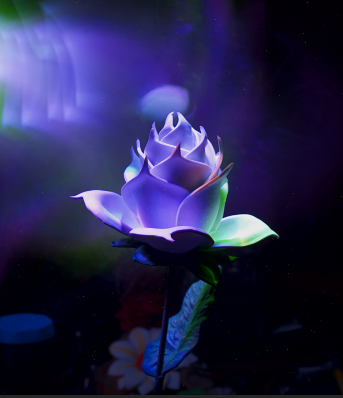
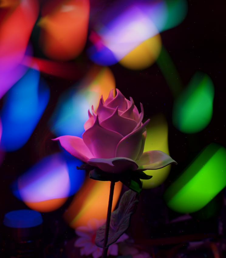
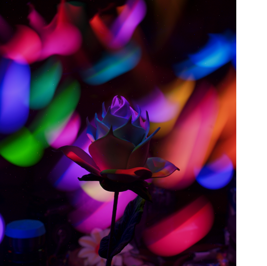
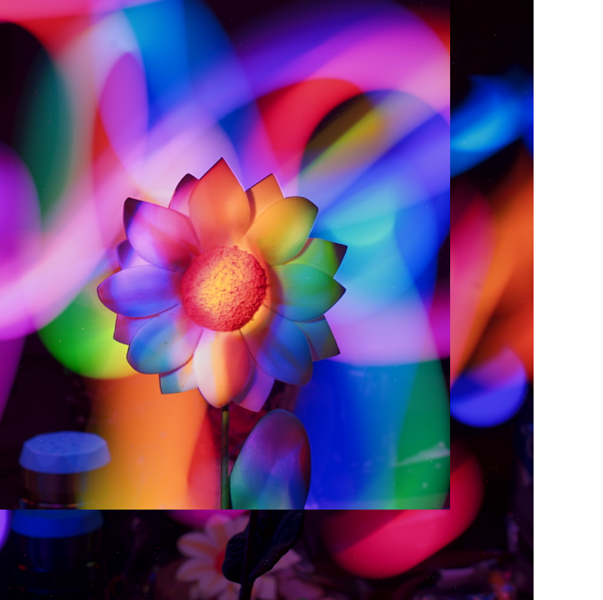
If you are new to Light Painting you can use the next tips.
Select a long exposure time: Usually between 10 to 30 seconds or even more.
Select a close aperture: use a aperture of f/8 to f/16.
Use self-timer: Select a 10 seconds self-timer to prepare the RGB Flashlight and the Xlights player.
Steps to follow on every photo:
- Select your sequence in xlights.
- Press the shutter and listen to the beeps of the self timer.
- Once the camera starts to capture the image press play on Xlights.
- Start painting with the RGB Flashlight.
- Practice timing and painting.
Enjoy flashing different color palettes on objects and create really great light painting photos!!!
Advanced Steps: Program Color Sequences Using Xlights
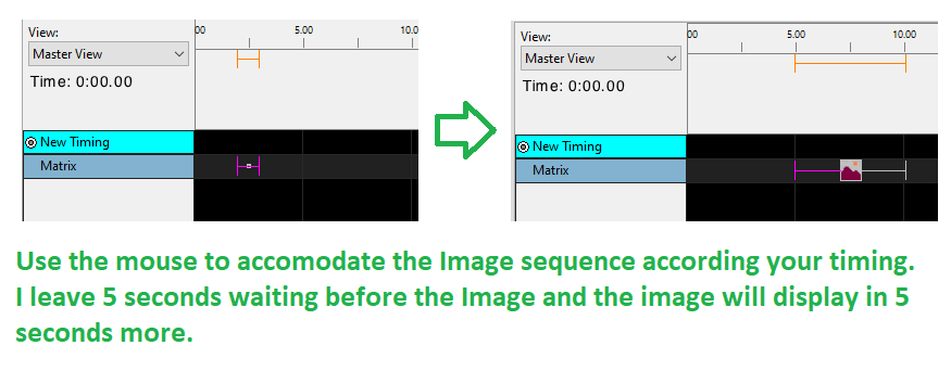
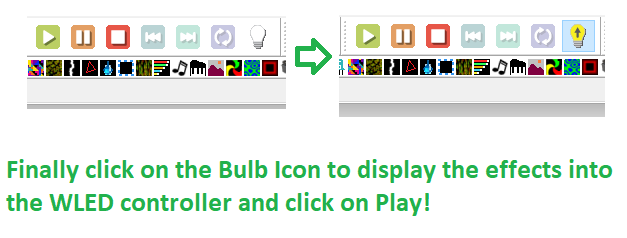
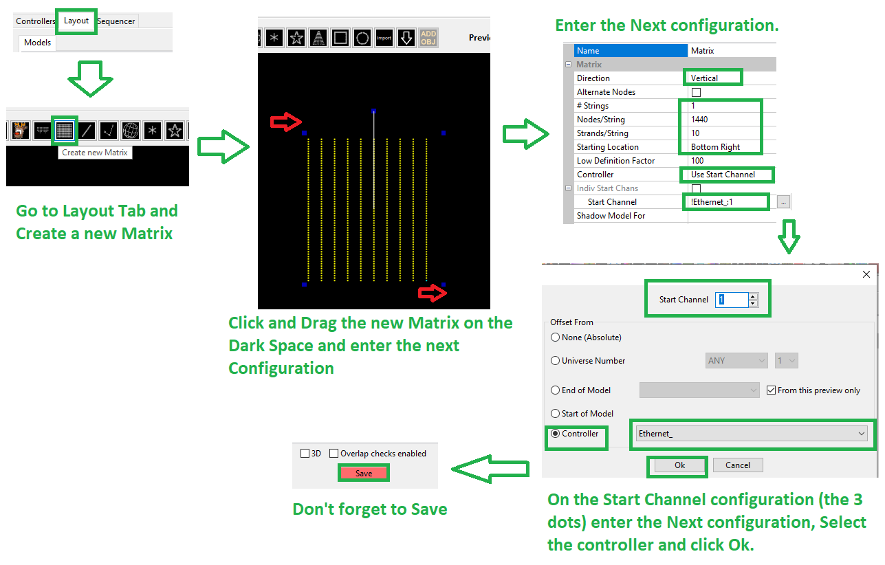
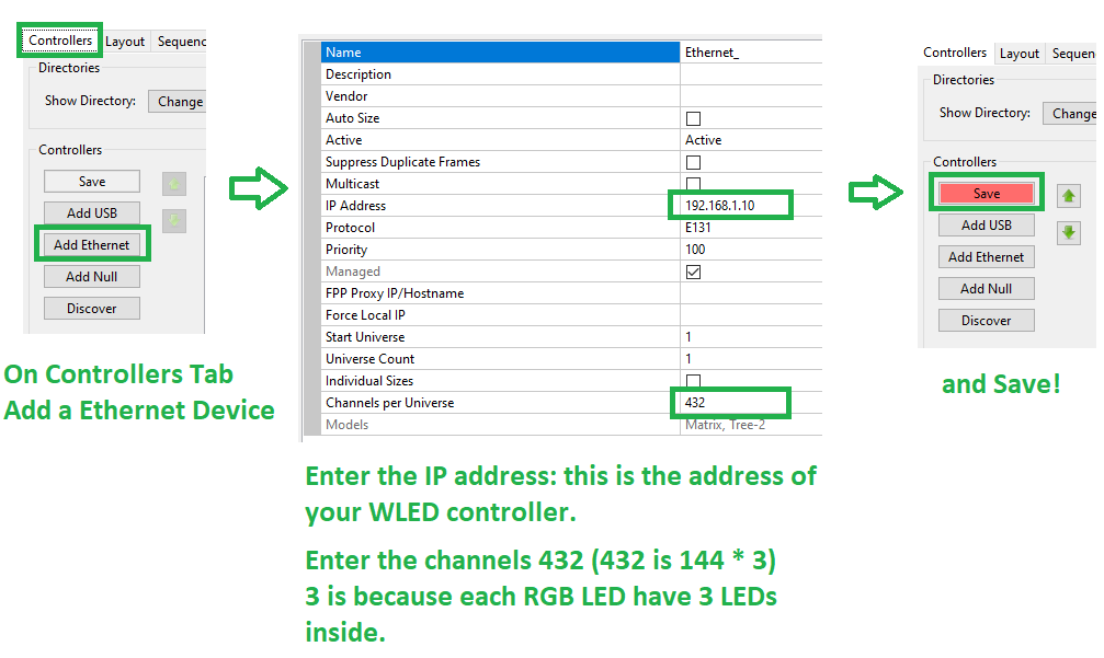
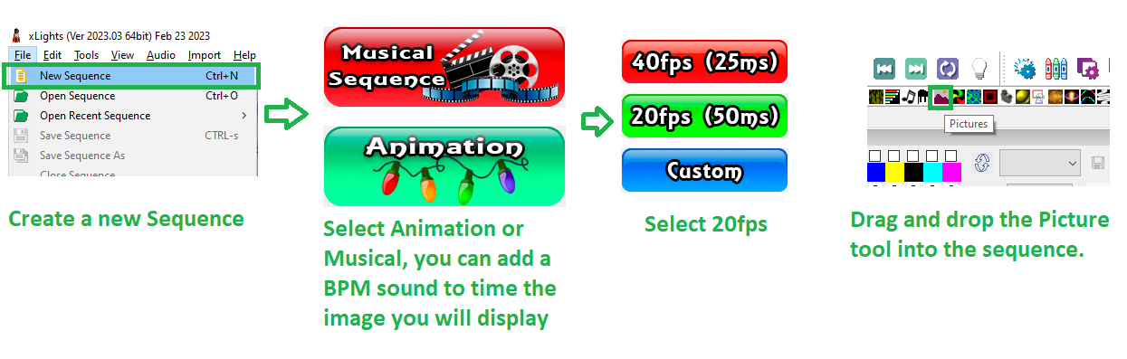
In order to program complex colors and patterns you can use the Xlights Software (that it was designed to control many lights but we will use it for program sequences of color and effects) it is really easy to use.
First we need to install it:
Download it from Xlights web page: https://xlights.org/releases/ and click on Download 64bits.
In Xlights we follow the next steps:
- We add a Ethernet controller.
- We enter the IP address of the WLED controller and the numbers of channels.
- And we click on Save.
- The we go to the Layout Tab and create a Light. click on the dark space and place the matrix.
- On the configuration of the Light we enter the parameters on the images above.
- And we click on save.
- The we go to the Sequencer Tab and we create a new sequence. We can use a song or only a sequence (by the way, if we use a song we can use a BPM track, this can help us on the timing to have an rhythm marker that way will be easier to use it by only one person).
- And click on Done.
- We select the color tools from the top and drag and drop the tool over the sequence line.
- We adjust the time of the color we will display I adjusted for 5 seconds of waiting time and 5 seconds for every color.
- Enable the controller by clicking on the Bulb Icon.
- And done! you can click on play and we can see the colors on the simulation.