Project Blindsense


The goal of this project is to restore awareness of surroundings to a blind animal. The device will determine the distance of objects in front of the animal and emit a vibration according to that distance.
Loss of vision has a great impact upon the life quality of anyone. This can be even worse for animals that lack support devices to aid them in navigating their environment. For this project the test case will be my dog, Freya. She lost her sight due to diabetes and now just simply navigating the house can be difficult. She has developed a habit of bulldozing over anything in her path.
Through Project: Blindsense I aim to give her awareness of objects in front of her and a general sense of how close it is.
Supplies
Circuit Board:
Input:
VL53L1X-SATEL (Time of Flight LIDAR Sensor)
Output:
Power:
Nine Volt Battery (with wire attachment)
Switch:
For this project I took the switch out of a AAA battery pack. Any switch that can remain on/off will work.
Other:
Copper Wire
Solder and Soldering Iron
Any casing that can accommodate the internal parts will work. For this project I used a 3D printer to make the case seen in the images.
Micro USB (for connecting a computer to the Arduino Nano)
Test Your Parts
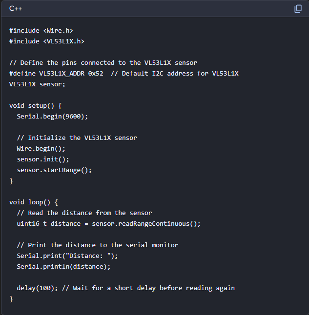
Before getting started on soldering all the parts together it is important to test them.
Loosely connect the Time-of-Flight Sensor to the Arduino Nano and connect the board to a computer with Arduino IDE installed.
The sketch attached to this step came from Copilot (the Microsoft AI tool) and works well enough to test the sensor and readings.
Make sure to download the necessary libraries on Arduino for your sensor.
Connect the Sensor

Now that we have verified the board and sensor are working, we can begin more permanently connecting the parts.
Where you start does not matter too much. Just be careful when soldering not to connect pins or wires that are not meant to be connected and to not have power from the battery connected to the board when it is interfaced with a computer.
For this instructable we will start with wiring the VL53L1X-SATEL (Time of Flight LIDAR Sensor) to the Arduino Nano.
The Image attached to this step is the pinout for the VL53L1X-SATEL when looking at it on the sensor side with the pins at the bottom. (Check the datasheet for your specific sensor before soldering)
The Arduino Nano makes this step easy, as the pins are labeled on the board for where to connect IRQ, XSHUT, SDA, and SCL. IRQ connects to RX, XSHUT connects to TX, SDA and SCL are labeled the same on the board (check your board's datasheet to be sure before soldering).
Before soldering the wires in place, take a moment to determine the placement of the components in your chosen casing. Get an idea of the length of wire needed to not cramp the casing while still giving you room to connect the remaining components.
Connect the Motor
Next we will connect the Vibration Motor to the Arduino Nano.
Connect the ground wire (blue for the motor I am using) to one of the two ground pins on the Arduino Nano.
Connect power (usually red) to a PWM pin on the Arduino Nano. (check the datasheet for your Arduino Nano for which of the available pins support pulse-width modulation)
As with the last step, be mindful of the length of wire you use when connecting you components.
Test Your Circuit Pt. 2

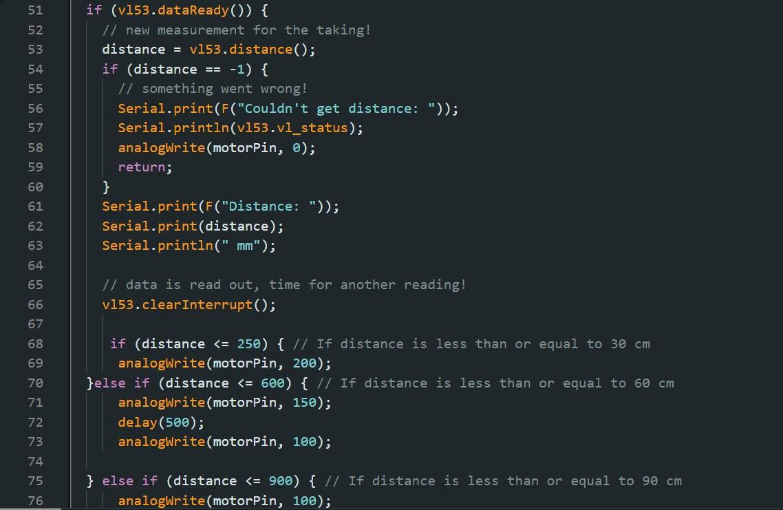
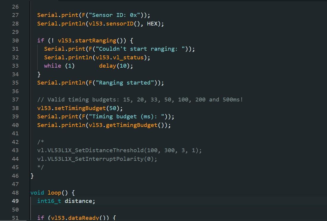
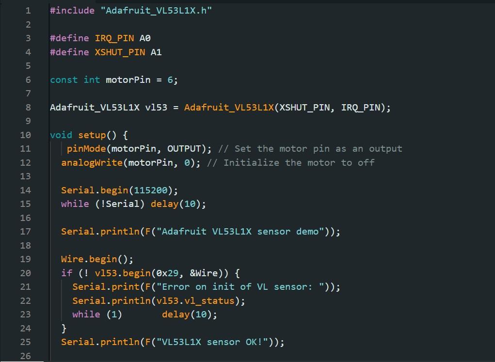

Now you should have your circuit connected and (hopefully) functional.
Use the sketch attached to this step or write your own to test your circuit.
In the "Loop" you can see the conditional statements for the reading and their outputs to the motor. Feel free to change these values to suite your needs. I have the vibrations pulsing, but you can set it to be a steady output instead.
The image here is from an earlier version of Project: Blindsense using an Arduino Uno.
Final Connections
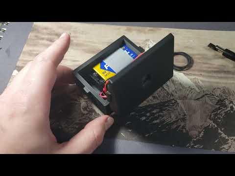
The last components to connect are the 9 Volt Battery to the Switch and then to the Arduino Nano.
Connect the power wire from the connector on the 9 Volt Battery to one prong on the switch. Then on the other side of the switch connect a wire from there to the VIN pin on the Arduino Nano. Last connect the ground wire to one of the ground pins on the board.
Make sure to do all the soldering without the battery connected to it's connector. It is also important that you do not have power coming from the battery when the Arduino Nano is connected to a computer.
Finalize

Now that the circuit is complete and it has been tested, it is time to consolidate it all in your chosen case. Depending on the tools at your disposal you can secure the components multiple ways. The current version is using hot glue and tape to secure the components but feel free to find more sophisticated methods.
Make sure the casing has a hole for the sensor (I used a bit of transparent plastic over the hole to protect the sensor. Either attach the switch to the outside of the case or have a second hole that the switch can peek out of.
You should now have a completed version of Project: Blindsense.
Retrospective

This design is not perfect and there are a few areas you might want to adjust if you desire to construct this for yourself. For a human the circuit should work excellently, but for a dog there are a few kinks that I still need to iron out.
The case I made was designed to angle up to account for the orientation of a collar around the dog's neck. This serves it's purpose, but there is the issue of how a dog (especially a blind one) holds their head while walking. When it's head is low to the ground it blocks the sensor making it vibrate.
One solution is to place the circuit on the back via a harness, but then there is the issue of when the dog holds its head up.
The best yet hardest to implement is to place it on the head so that it senses wherever the dog is looking.