Project Gestalt

by Arnov Sharma in Circuits > Raspberry Pi

1840 Views, 10 Favorites, 0 Comments

Project Gestalt

PROJECT GESTALT: Meet the Matrix
PROJECT GESTALT: Here's What It Can Actually Do
59.gif
58.gif
54.gif
46.gif
56.gif
IMG_E0166.JPG
IMG_E0179.JPG
Thumbb.JPG

Greetings everyone, and welcome back!

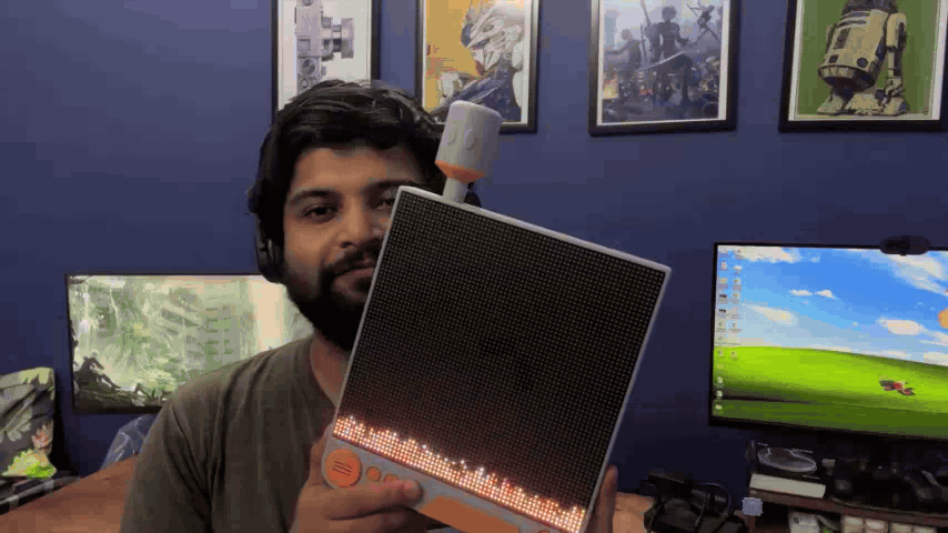
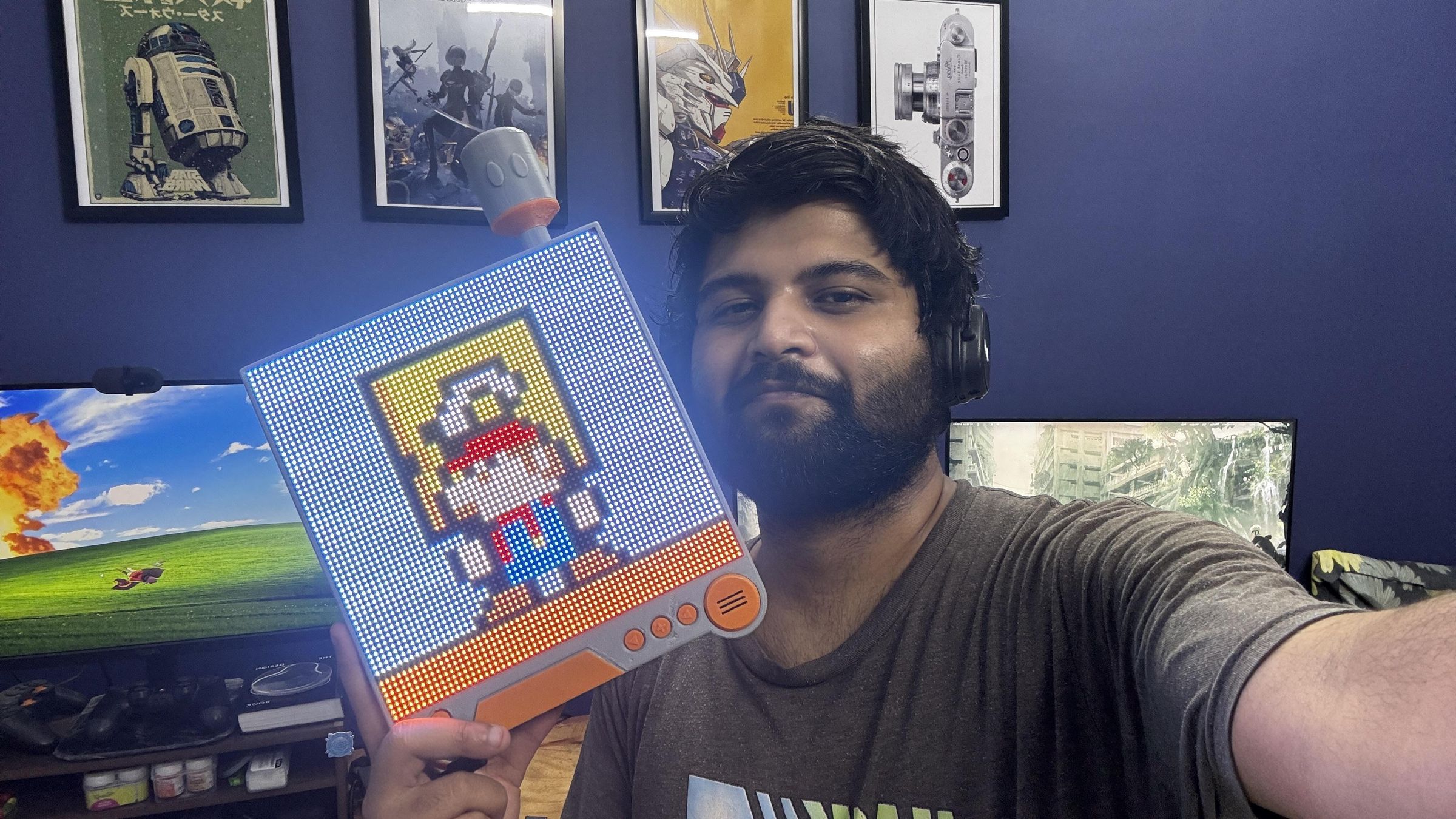
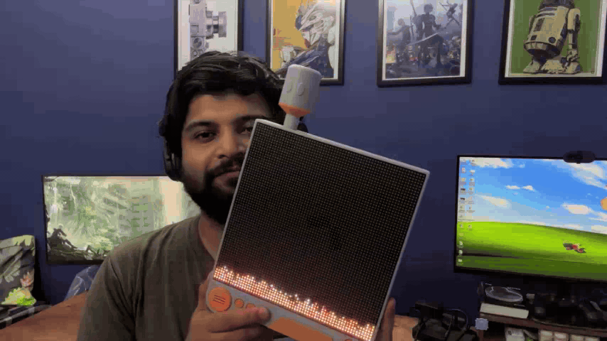
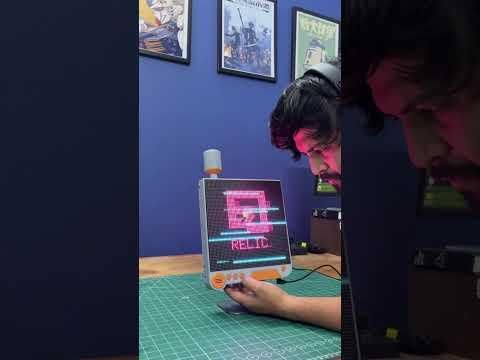
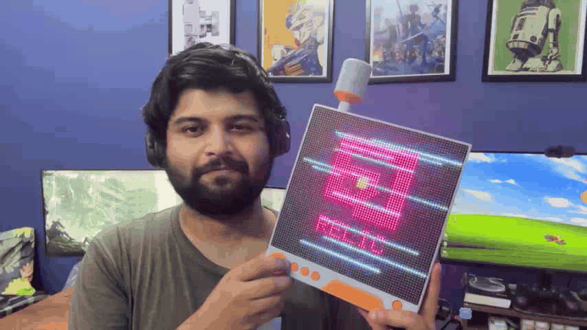
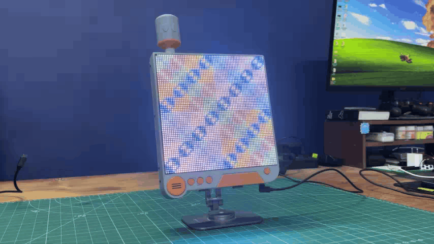
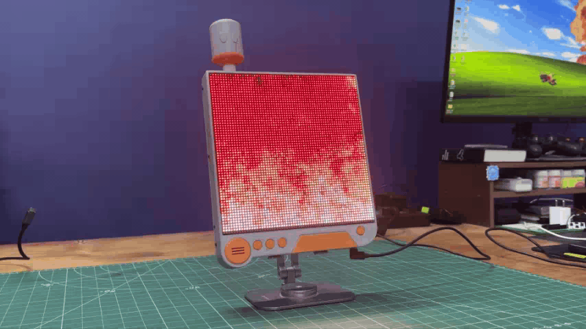
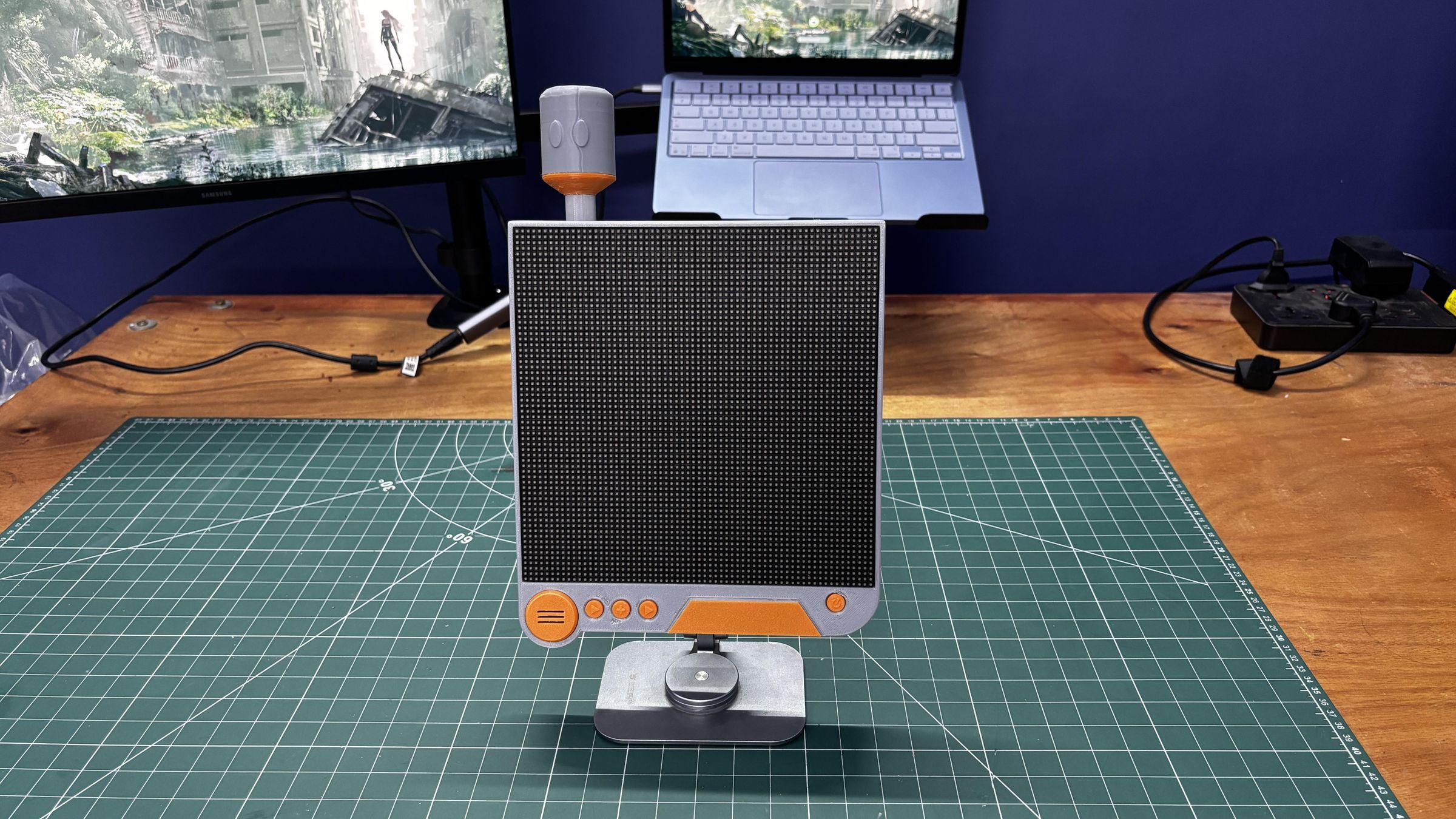
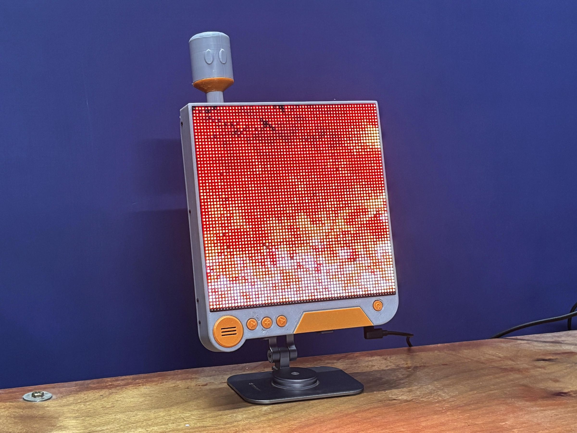
This is Project Gestalt, a DIY wall-mounted RGB matrix display that I built from scratch. It features two 64×32 RGB LED matrices chained together to create a single 64×64 display, all driven by a Raspberry Pi Pico.

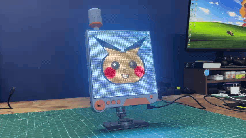
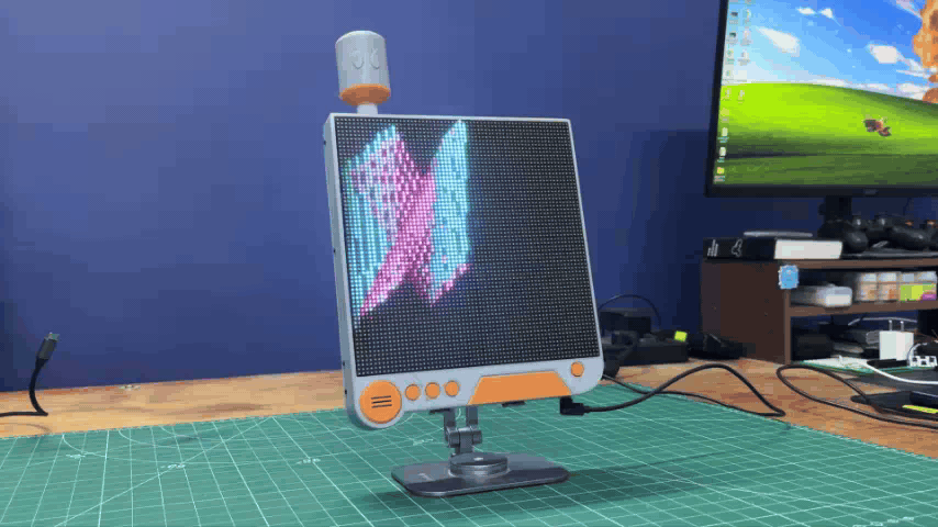
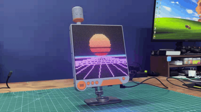
The device can display various animations and visuals that I’ve added, including gaming-related animations, random patterns, and several other effects.

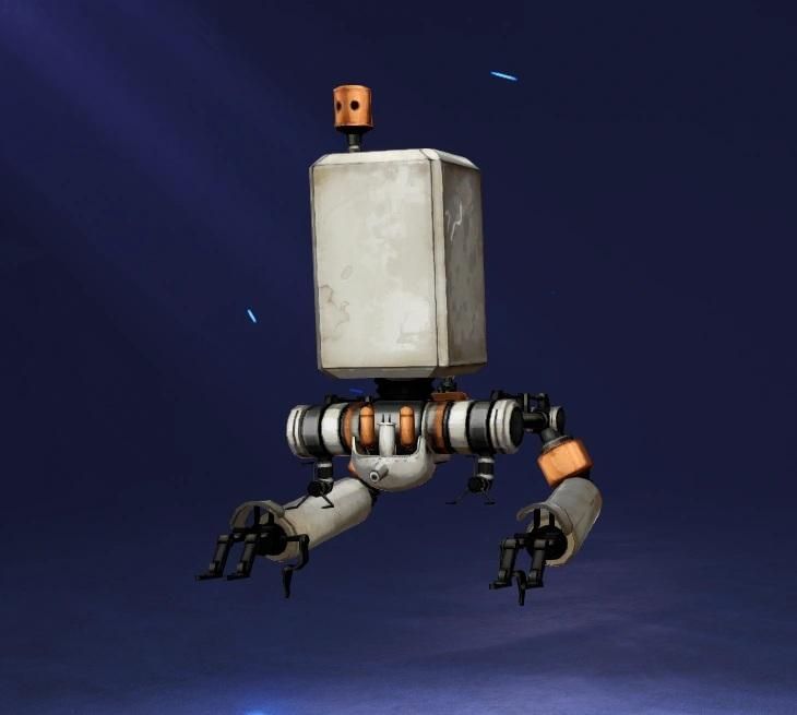
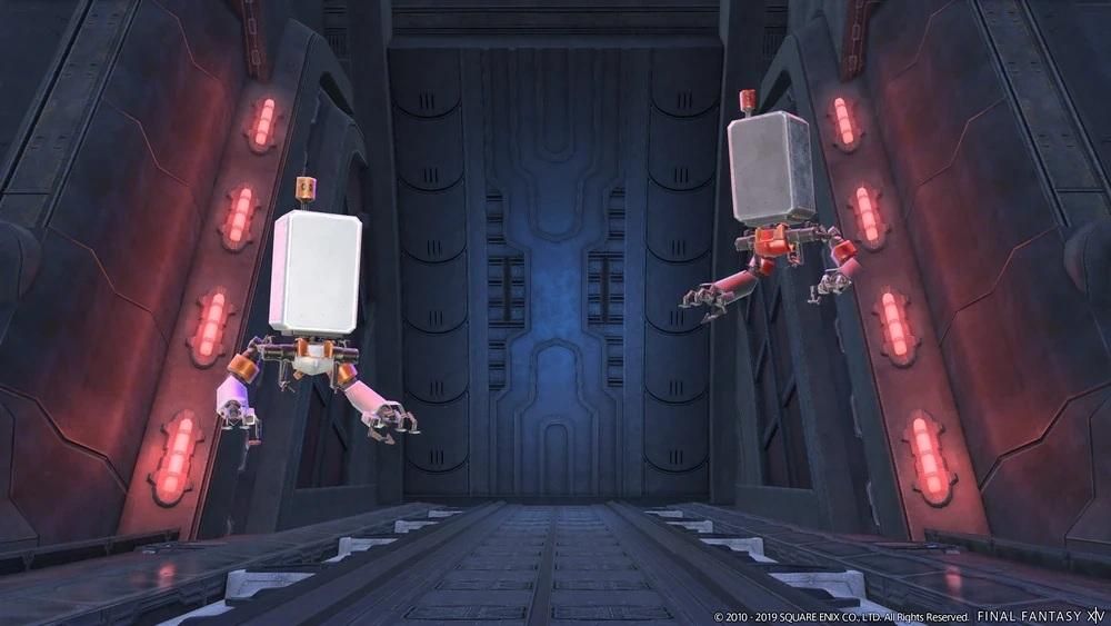
The entire enclosure was designed in Fusion 360, with its design heavily inspired by the Pods from NieR: Automata. This is also where the name “Gestalt” comes from. Gestalt is a German word that roughly translates to “form” or “shape,” and it also refers to the idea of individual elements coming together to form a complete whole. I thought this was a fitting name for a project where two separate RGB matrices come together to create one complete display.

Project Gestalt is powered by a 3.7V, 2600mAh lithium-ion cell, providing approximately four hours of battery backup, which is pretty decent for a device running a total of 4,096 RGB LEDs.

I have previously worked on a similar project called WaveForm, where I used a single 64×32 RGB matrix along with a microphone to detect surrounding sound and display an audio-reactive waveform. As the sound level increased, the waveform displayed on the matrix reacted accordingly.

I liked that feature so much that I decided to implement the WaveForm code in Project Gestalt as well.

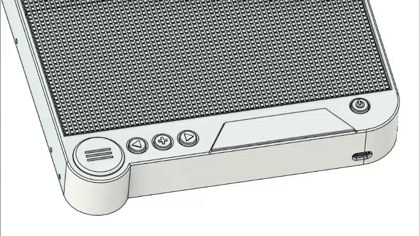
For controlling the device, I added three buttons: Previous, WaveForm, and Next. The Previous and Next buttons allow us to cycle backward and forward through the different animations stored on the device.

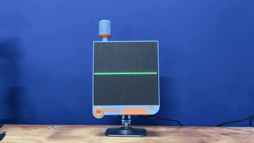
Pressing the WaveForm button switches the device into WaveForm mode. In this mode, the RGB matrix displays an animated waveform that reacts in real time to the sound picked up by the onboard microphone.

In this Instructables, I’ll cover the complete build process of Project Gestalt, including the enclosure design, electronics, assembly process, and code.

Let’s get started!

Supplies

These were the materials used in this project—

  1. Custom PCBs
  2. 64x32 P3 HUB75 RGB Matrix x 2
  3. Matrix Ribbon Connector
  4. Raspberry Pi PICO
  5. IP5306 Power Management IC
  6. 10 uF Capacitors
  7. 1 uH SMD Inductor
  8. Type C Port
  9. 0805 LED Indicator
  10. 10K Resistor: 0805 Package
  11. Lithium cell 3.7V 2600mAh with PCM
  12. Push Buttons 12x12 Size
  13. Push Buttons 6x6 Size
  14. Connecting Wires

PODS FROM NieR: AUTOMATA
NieR_Series_x_Final_Fantasy_VII_Ever_Crisis_2B.jpg
Pod_042_%28Crystal_of_Atlan%29.jpg
FFXIV_YoHRa_Pods.jpg

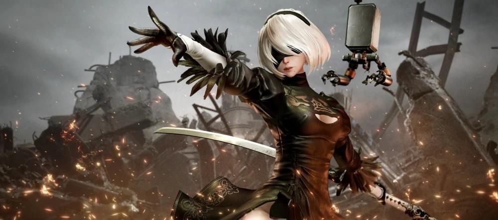
The inspiration behind this project came from PODS from NieR: Automata.

For those unfamiliar with NieR: Automata, Pods are tactical support units commonly assigned to YoRHa soldiers. They are equipped with various weapons for long-range attacks, relay messages from Command, exchange operational intelligence between units, and provide general support during missions.

Throughout most of the game, Pods appear to be emotionless machines that simply follow orders. Their dry and overly literal conversations also occasionally provide some of the funniest moments in the game. However, by the end of NieR: Automata, their role becomes much more profound. Without going too deep into spoiler territory, the Pods begin to represent something beyond their original programming, making them an unexpectedly meaningful part of the story.

As someone who really likes NieR: Automata, I had wanted to build my own Pod-inspired device for quite some time, something that I could place on my workbench as a functional piece of gaming memorabilia.

Interestingly, the RGB matrix display wasn’t actually part of the original idea. The project initially started simply as an attempt to design and build my own Pod-like device. The idea of incorporating two RGB matrices and turning it into an interactive display came later during the design process.

This eventually resulted in Project Gestalt: a device that combines the visual design of the Pods from NieR: Automata with a 64×64 RGB matrix capable of displaying animations, gaming-related visuals, random patterns, and an audio-reactive waveform.

DESIGN
untitled.800.png
untitled.801.png
64.gif
65.gif
66.gif
67.gif
68.gif
untitled.798.png
untitled.799.png

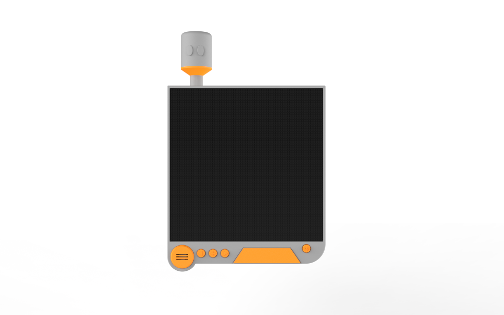
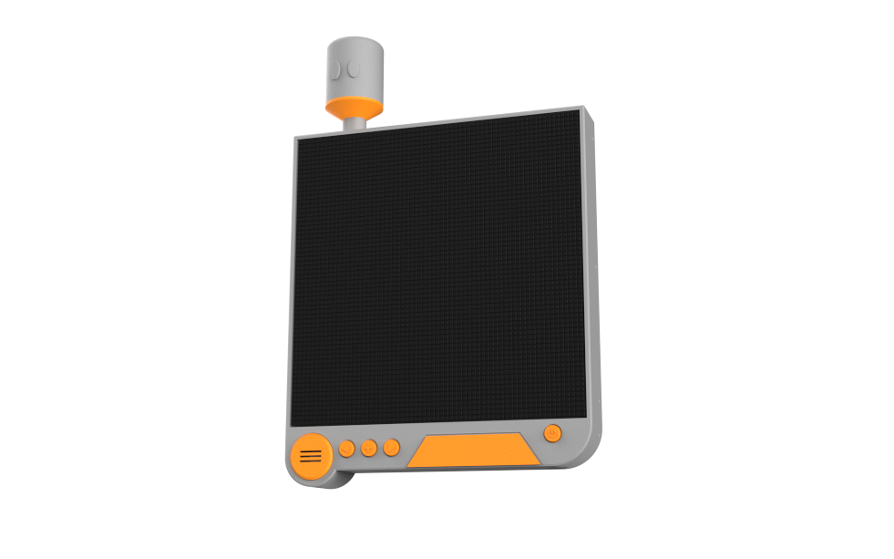
For the enclosure design of this project, my primary inspiration was the Pod from NieR: Automata, more specifically Pod 042, which is assigned to 2B. While all Pods share the same overall design, Pod 042 is distinguished by its orange accent pieces, making it instantly recognizable.

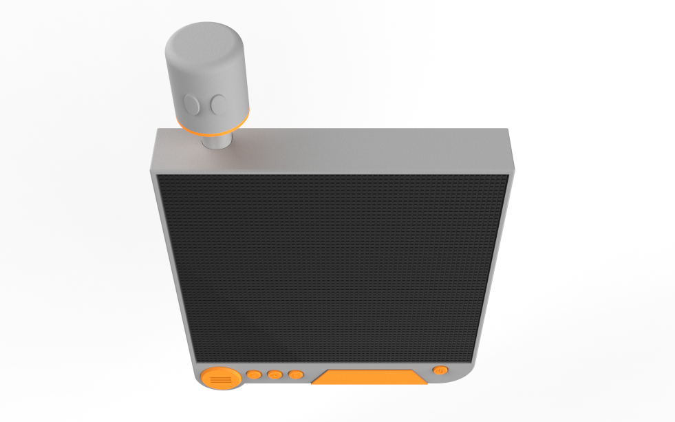
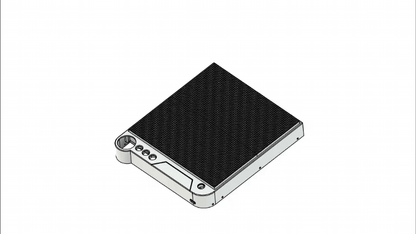
The original Pod has a fairly boxy design, whereas the RGB matrix is almost completely flat. Because of this, I couldn't create an exact replica and instead designed an enclosure that captures the overall look while accommodating the display. One feature I wanted to preserve was the cylindrical top section with its two eye-like details, which is one of the most recognizable elements of the Pod's design.

To achieve a metallic appearance, I planned to print the majority of the enclosure using grey PLA, with separate orange accent pieces to resemble Pod 042.

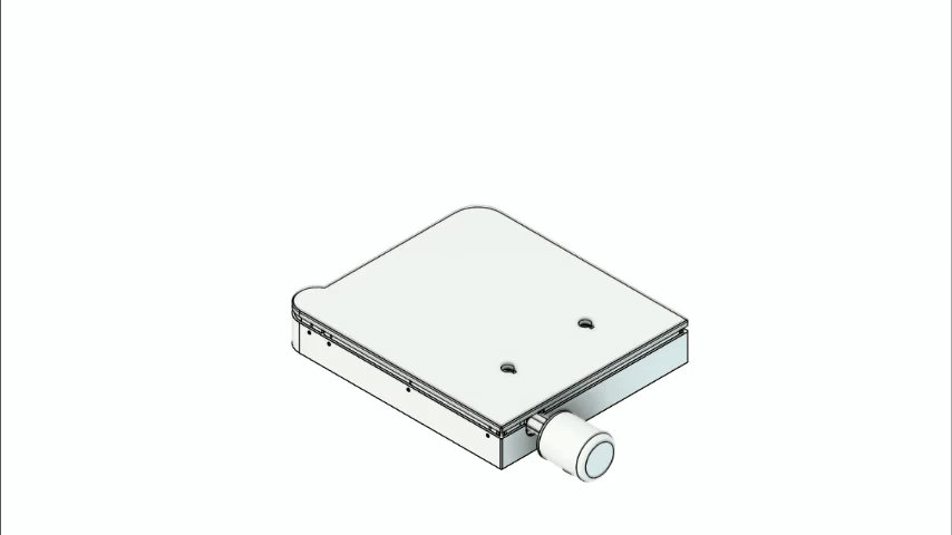
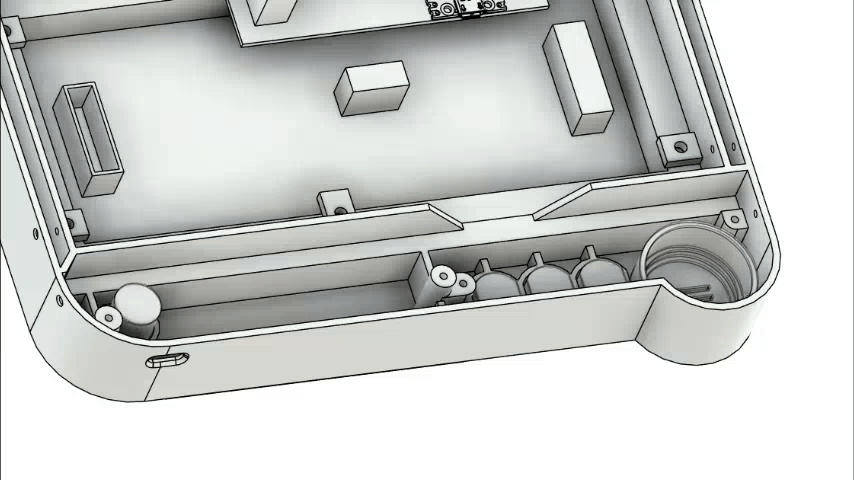
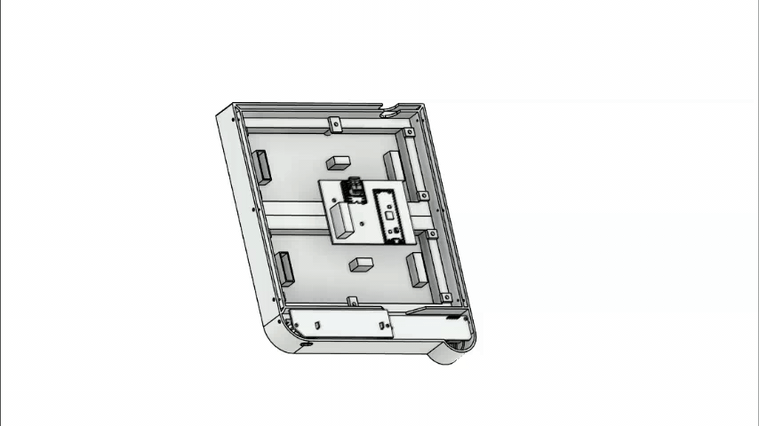
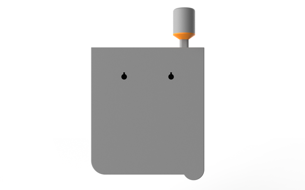
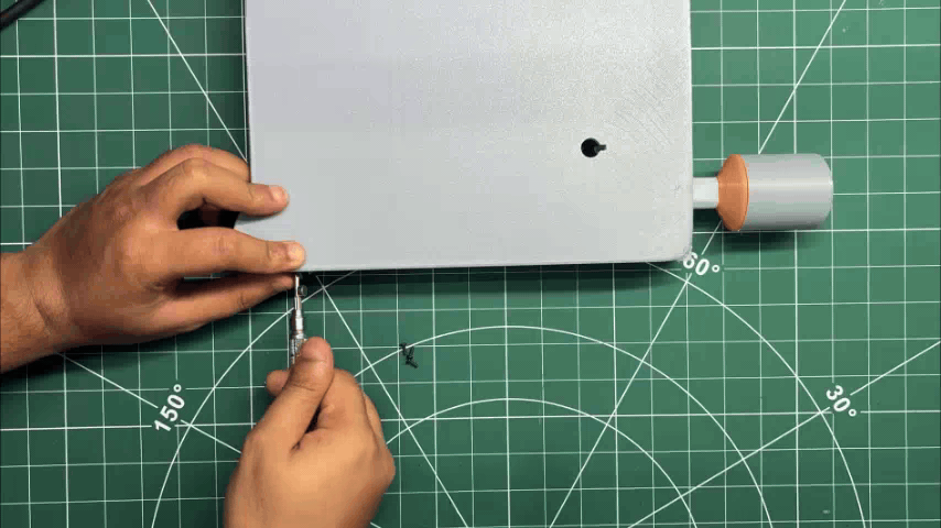
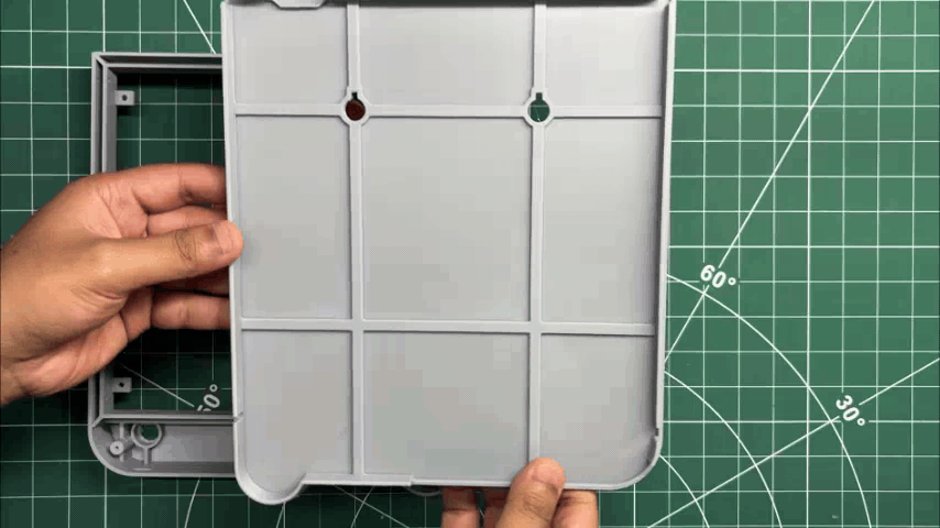
The enclosure consists of two main parts: the Main Body and the Back Lid. The Main Body houses both RGB matrices, the Pico Driver Board, the Switch Board, the power switch, the front grille, and the switch actuators. The Back Lid closes the enclosure from the rear and is secured using M2 screws.

The cylindrical Pod-inspired top section is sandwiched between the Main Body and the Back Lid, holding it securely in place without requiring additional fasteners. Finally, an orange accent piece is attached to the front of the enclosure using super glue, completing the overall Pod-inspired appearance.

3D PRINTED PARTS
26.gif
27.gif
IMG_E0112.JPG
IMG_E0113.JPG

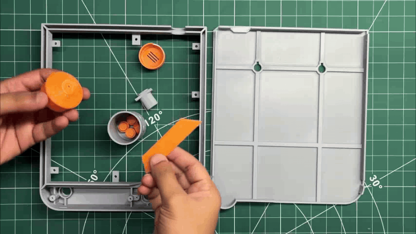
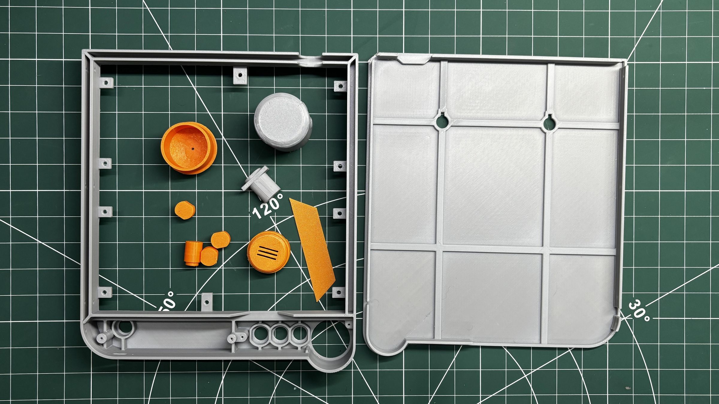
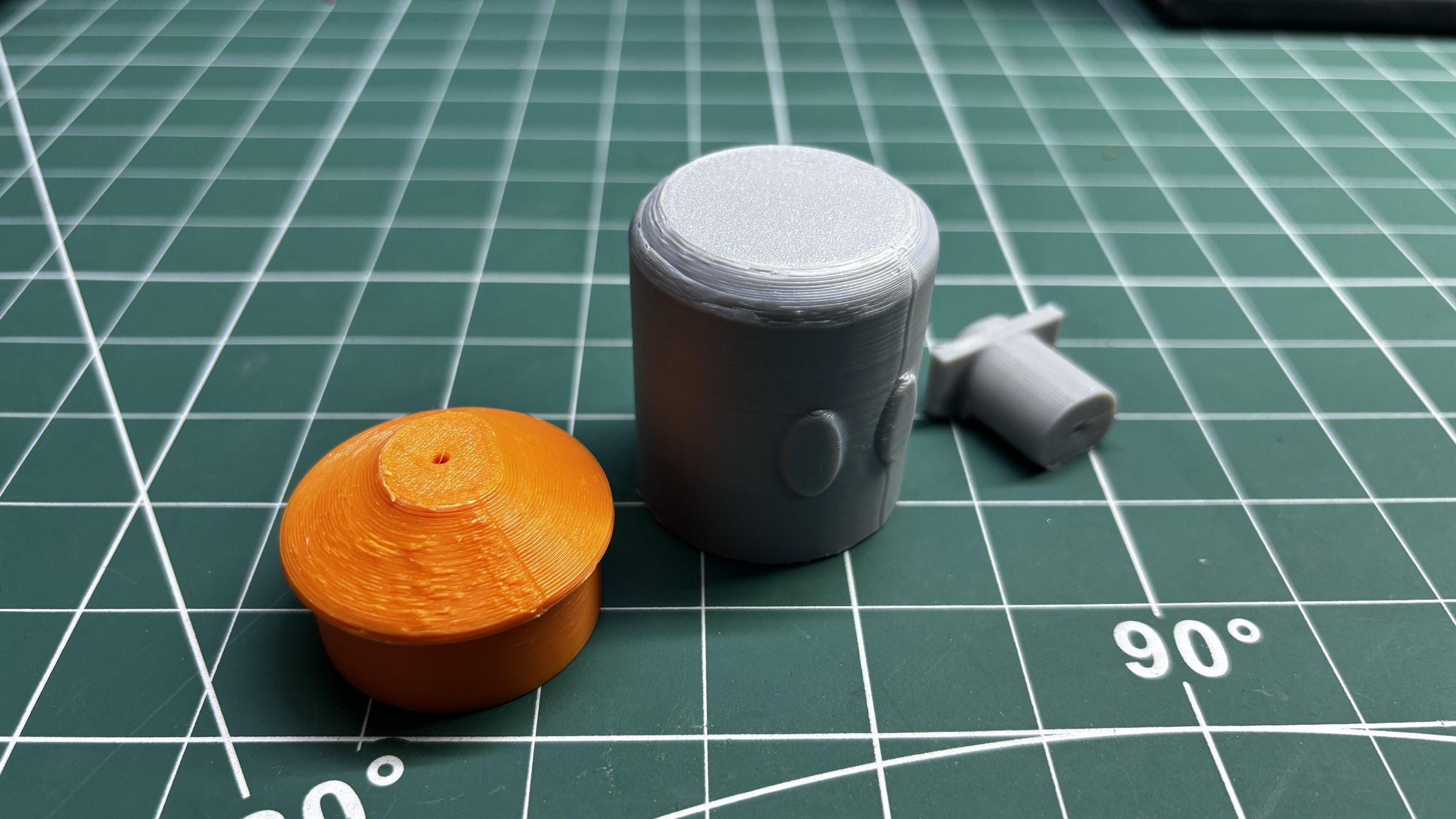
Once the enclosure design was complete, all the parts were exported as mesh files and 3D printed on my Anycubic Kobra S1 using Grey Hyper PLA and Orange Hyper PLA.

The larger structural components, including the Main Body, Back Lid, and Pod-inspired Cylinder were printed in Grey Hyper PLA, while the grill, button actuators, and front accent piece were printed in Orange Hyper PLA, giving the project a clean dual-tone aesthetic inspired by Pod 042.

For most of the prints, I used the following settings:

  1. Layer Height: 0.2 mm
  2. Infill: 25%
  3. Nozzle: 0.4 mm
  4. Supports: Tree Supports with a 0.3 mm Top Distance

These settings provided a good balance between print quality, strength, and print time.

HARDWARE- 64x32 RGB MATRIX
10.gif
FBHX9U0M5CHBL7L.jpg
FEJ1VSAM5CHBL8C.jpg

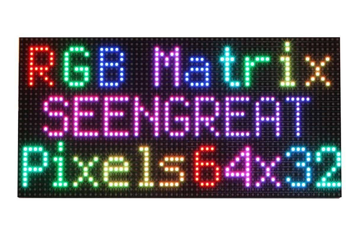
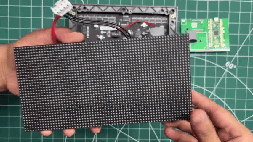
For this project, we are using two 64x32 RGB matrix panels, each consisting of 2048 RGB LEDs arranged in a 64-by-32 grid, producing vibrant text, images, and animations.

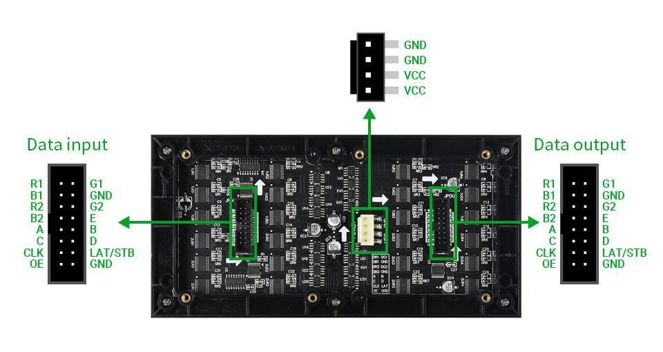
This panel is controlled using a HUB75 interface, which relies on multiple control pins, including RGB pins, address pins, a clock pin, a data latch, and an output enable pin.

The HUB75 connection enables the row-column scanning method by shifting a row of pixel data into a shift register, then using a demultiplexer to select which rows to display. The HUB75 connector includes RGB channels, addressing pins (A, B, C, D), a clock signal (CLK), a latch signal (LAT), and an output enable (OE) pin.

This interface allows precise control over the LED matrix, enabling smooth and bright displays ideal for text, images, and animations.

While it might appear complex to set up, this method ensures high-intensity displays and smooth, seamless graphics transitions.

Using a 5V power source, we can drive this display, but there's a catch. The current draw can vary significantly depending on the number of LEDs lit and their brightness levels. A fully lit panel can draw substantial current, so a power supply capable of providing at least 4-5 Amps is recommended.

Additionally, by utilizing the included IN and OUT connectors, we can connect multiple panels in pairs and form a chain. One of the challenges of connecting numerous panels is ensuring that the control solution (PICO 2) we are employing can handle the extra data load of two or more displays.

With the PICO 2, we are currently using a single panel that can power two or more displays without causing any issues.

Waveshare made this matrix, and the wiki link below has more detailed information on the Matrix board:

https://www.waveshare.com/wiki/RGB-Matrix-P3-64x32

PCB DESIGN- PICO DRIVER

Screenshot 2026-07-12 141139.jpg
PICO DRIVER_page-0001.jpg
Screenshot 2026-07-12 141113.jpg
Screenshot 2026-05-10 011653.jpg

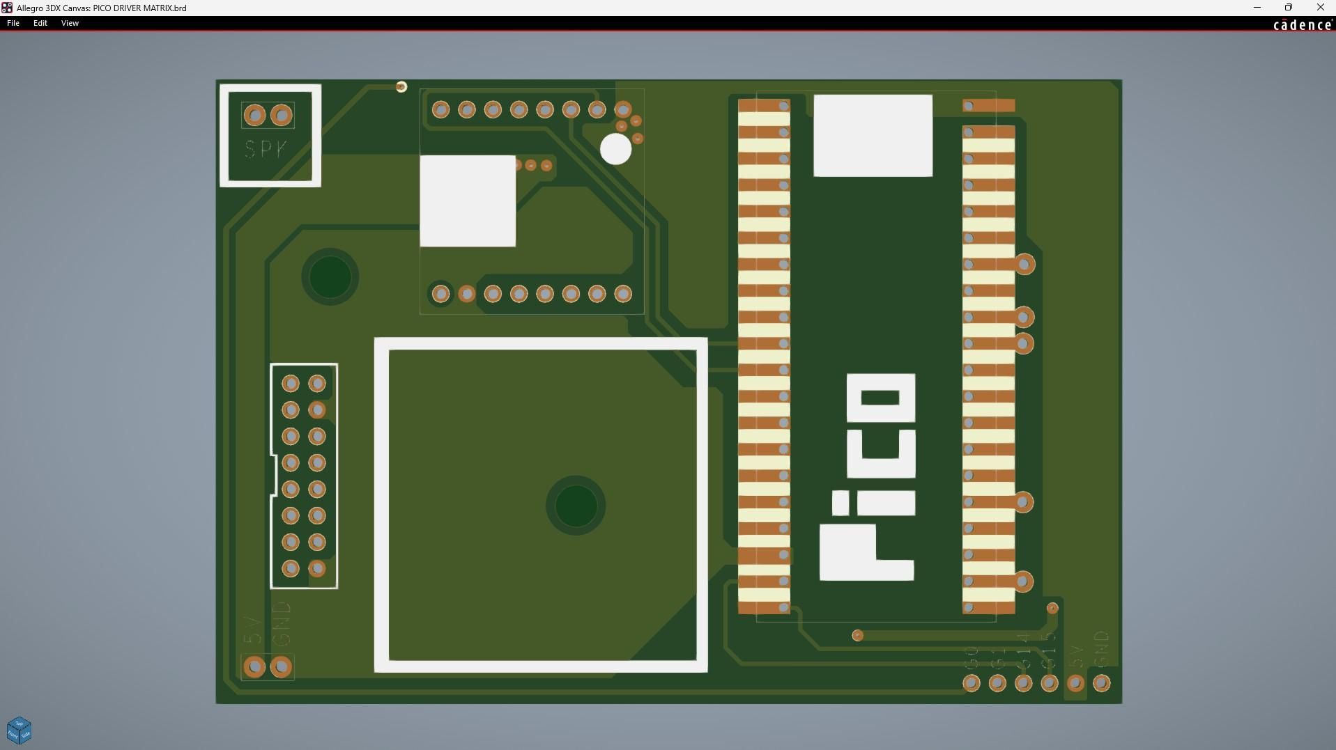
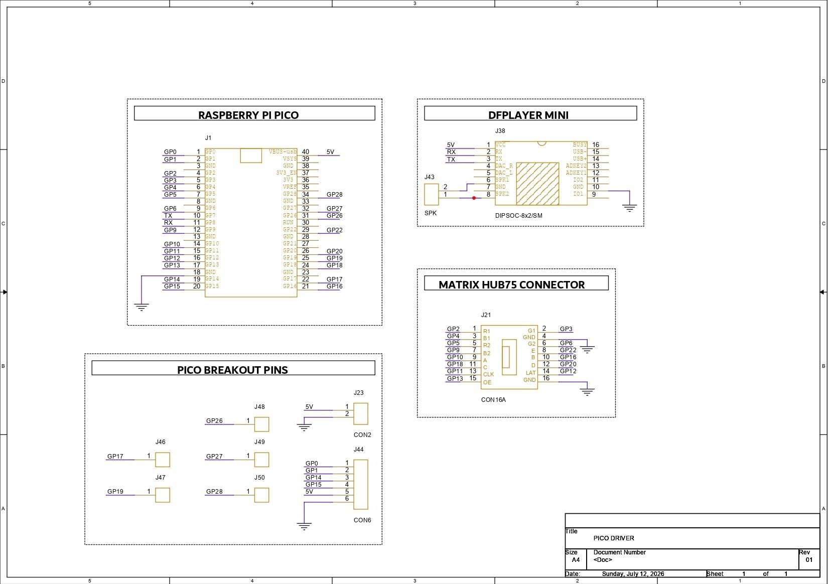
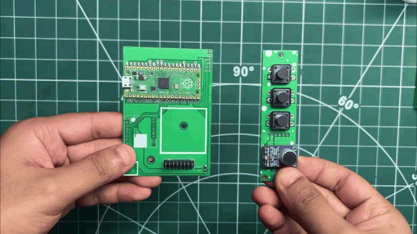
The first PCB designed for this project was the Pico Driver Board, which acts as the main controller for Project Gestalt. It interfaces the Raspberry Pi Pico 2 with the RGB matrix through a standard HUB75 (CON16) connector.

The HUB75 signals are connected to the Pico as follows:

  1. A to GPIO19
  2. B to GPIO16
  3. C to GPIO18
  4. D to GPIO20
  5. E to GPIO22
  6. CLK to GPIO11
  7. LAT/STB to GPIO12
  8. OE to GPIO13
  9. R1 to GPIO2
  10. G1 to GPIO3
  11. B1 to GPIO4
  12. R2 to GPIO5
  13. G2 to GPIO8
  14. B2 to GPIO9.

A CON2 connector is also included, which connects to the Pico's 5V and GND pins to provide power to the Driver Board.

Additionally, we added a CON6 connector that breaks out several GPIO pins. This connector will later be used to connect the tactile buttons and the microphone module.

The PCB also includes footprints for a DFPlayer Mini audio module. Although it is not used in Version 1 of this project, I decided to include it on the board so audio functionality can be added easily in a future revision.

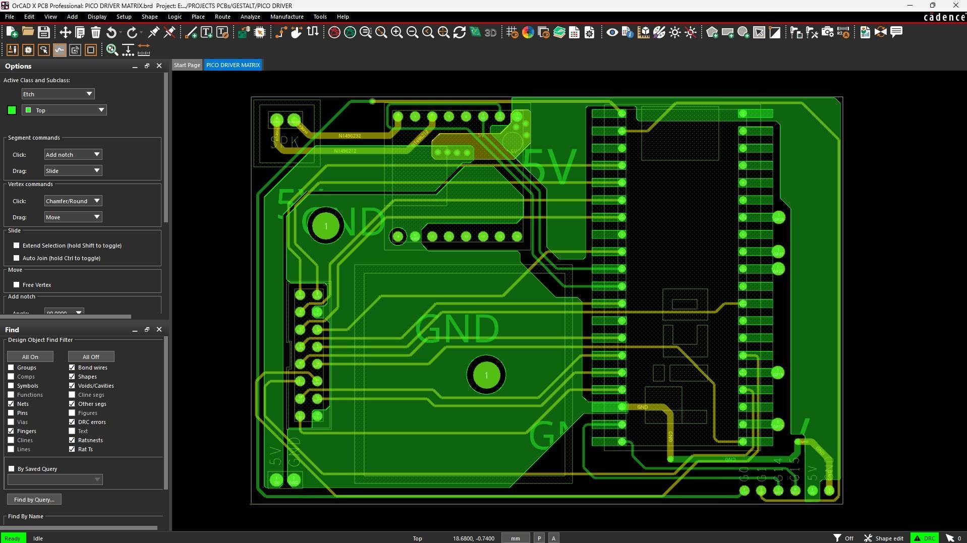
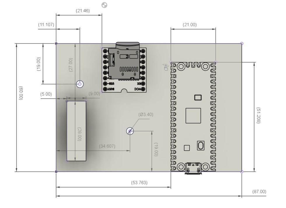
Once the schematic was completed, the PCB outline was created based on the dimensions of the 3D model. After placing the mounting holes were placed, all the components and connectors were positioned, and the board routing was completed.

PCB DESIGN- SWITCH BOARD
Screenshot 2026-07-12 141251.jpg
SWITCH BOARD_page-0001.jpg
Screenshot 2026-07-12 141220.jpg
Screenshot 2026-05-10 010404.jpg

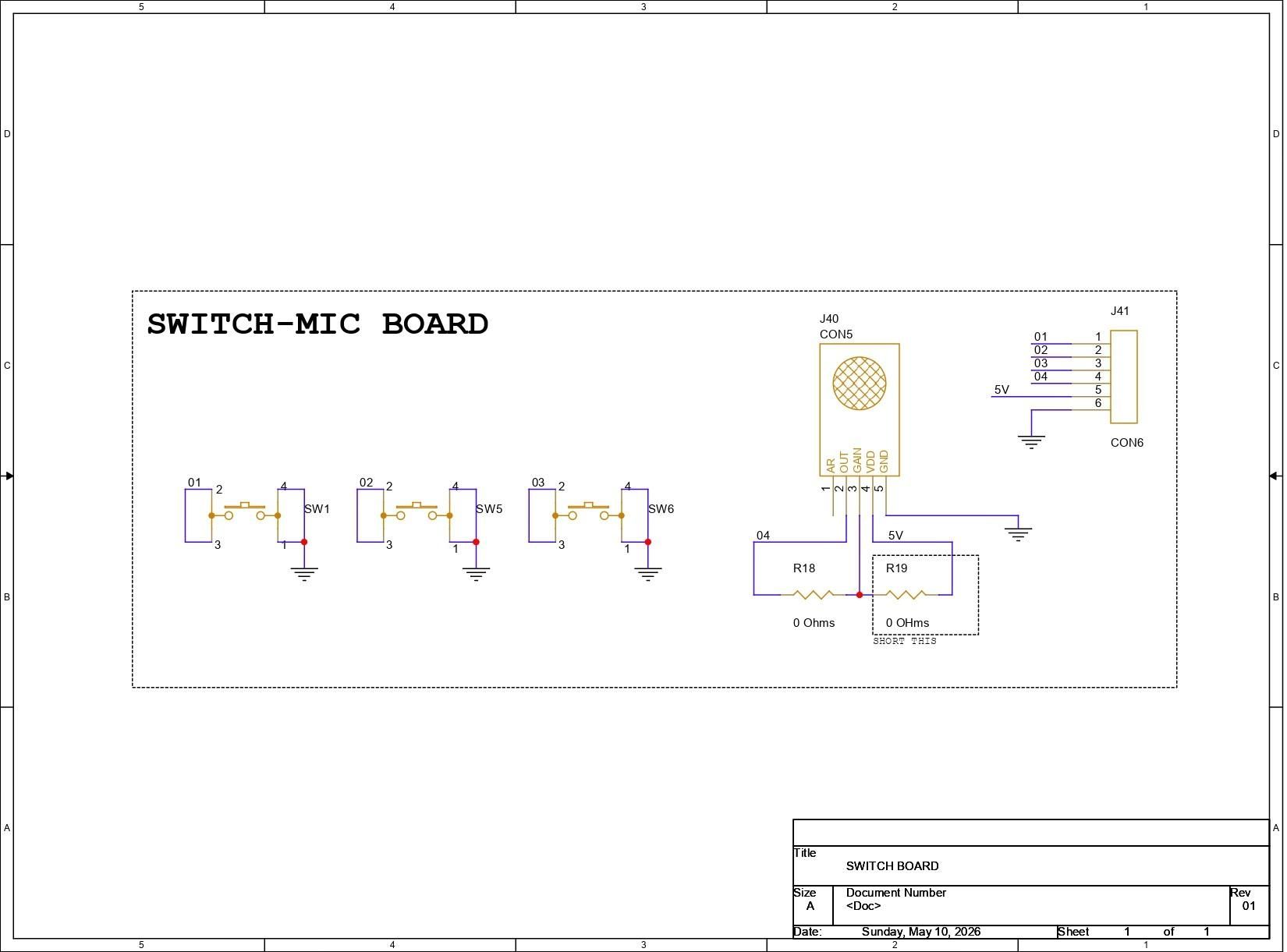
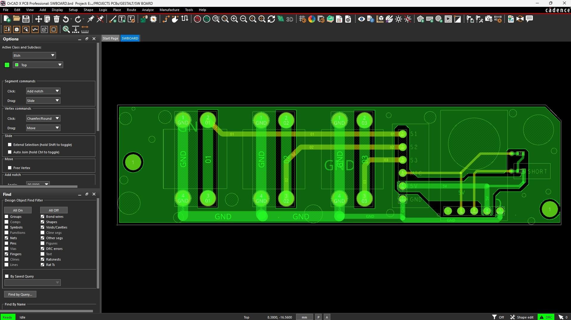
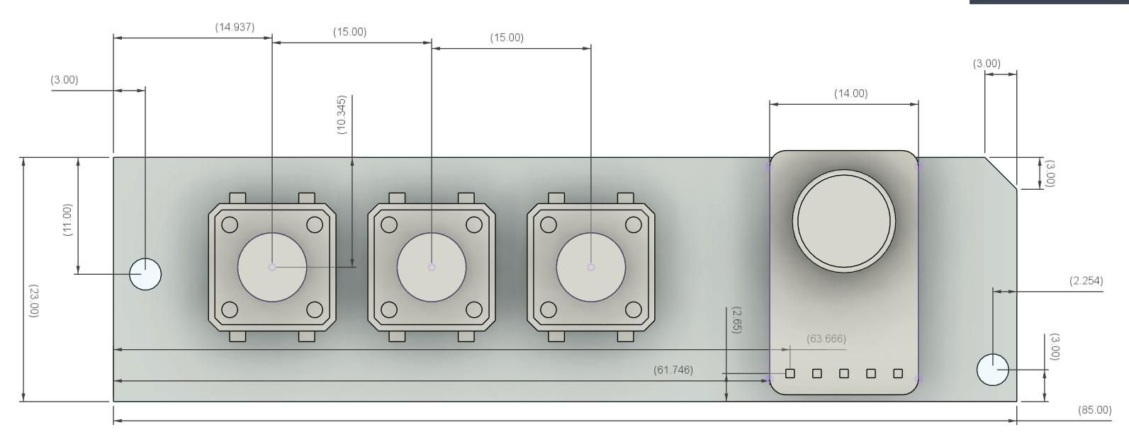
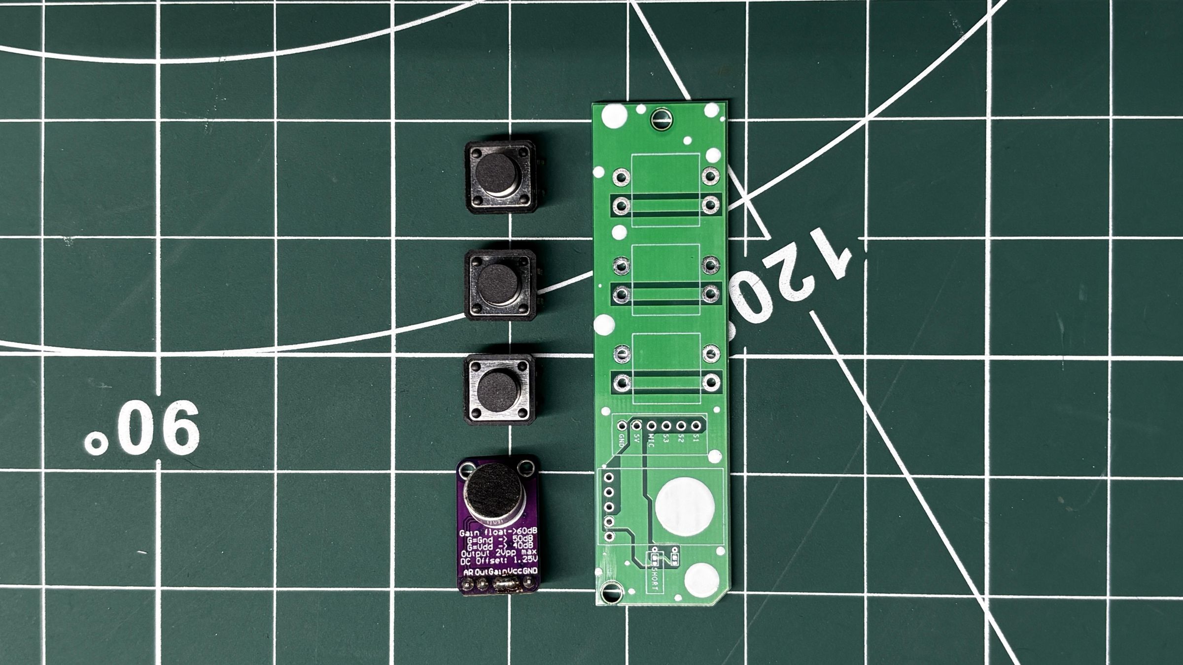
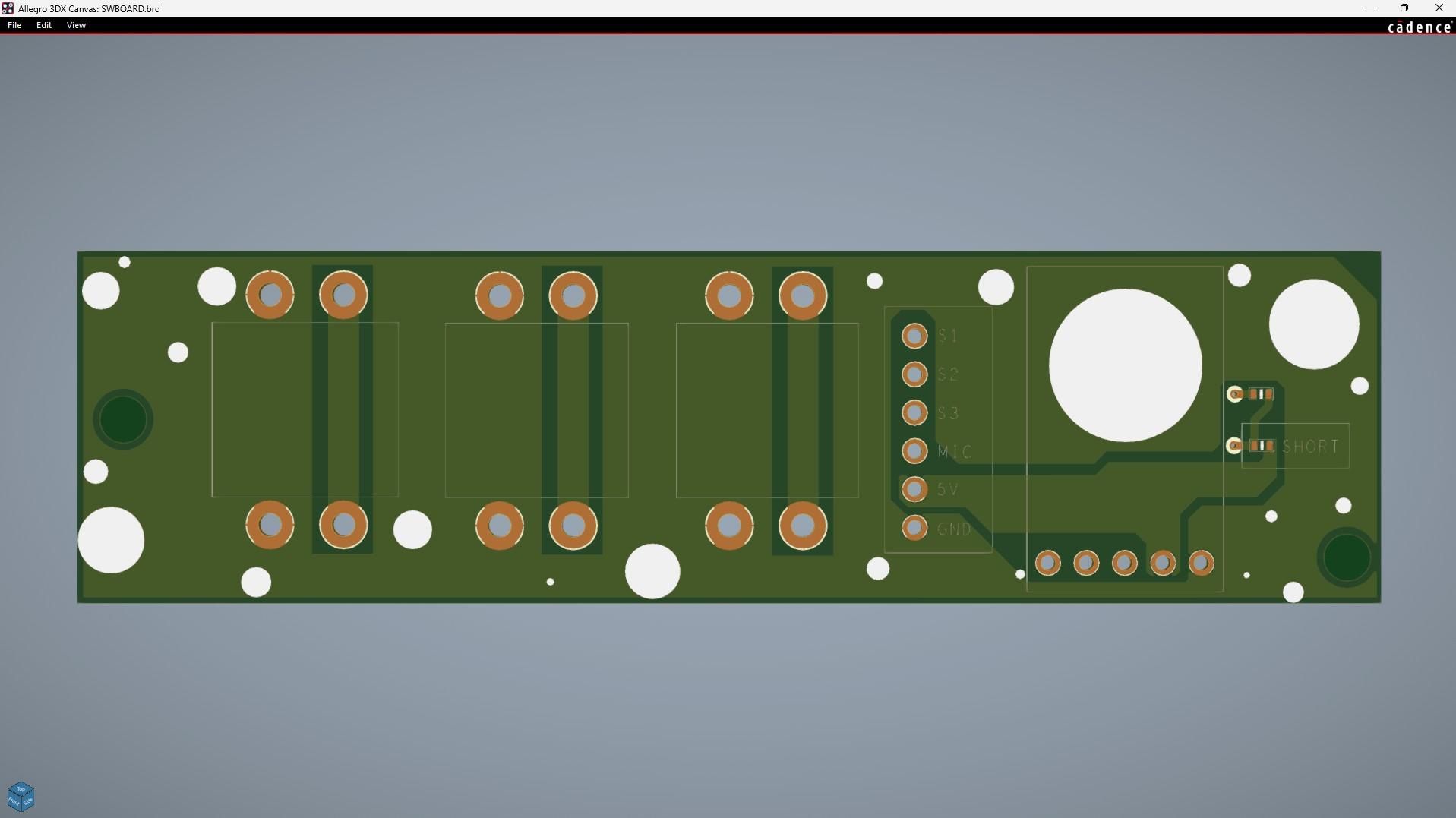
Next, we designed the Switch Board, which houses three 12×12 mm tactile push buttons along with the microphone module.

The three push buttons are connected with one terminal tied to GND, while the other terminals are routed individually to a CON6 connector. This connector interfaces directly with the Pico Driver Board and carries the button signals.

A MAX9814 microphone module is also included on this board. Its output signal, along with the VCC and GND connections, is routed through the same CON6 connector, allowing the Raspberry Pi Pico to read the surrounding audio for the WaveForm mode.

Just like the Pico Driver Board, the PCB outline was created using the dimensions from the 3D Model. After positioning the switches and connectors, the traces were routed to complete the board design.

PCB DESIGN- POWER BOARD
Screenshot 2026-07-12 141039.jpg
POWER BOARD_page-0001.jpg
Screenshot 2026-07-12 140950.jpg
Screenshot 2026-05-10 010858.jpg
Screenshot 2026-05-10 033602.jpg

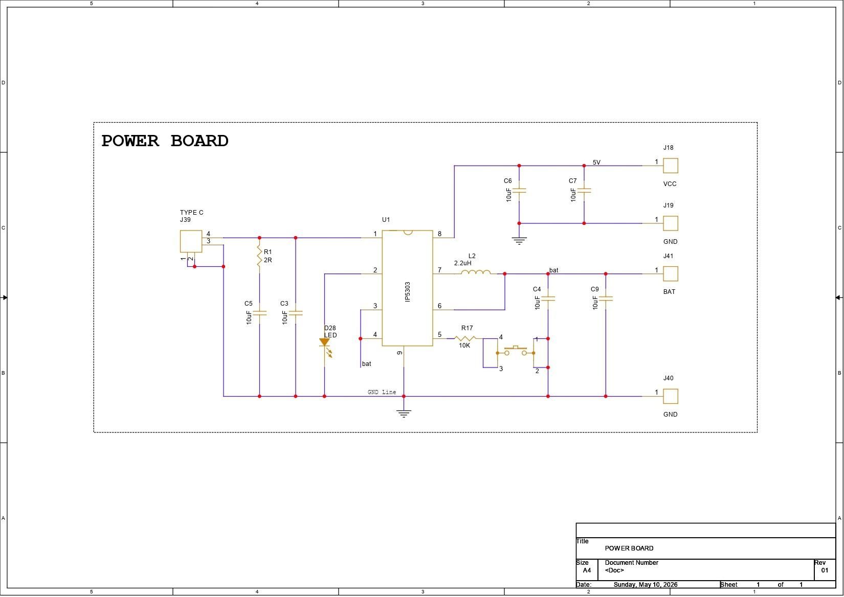
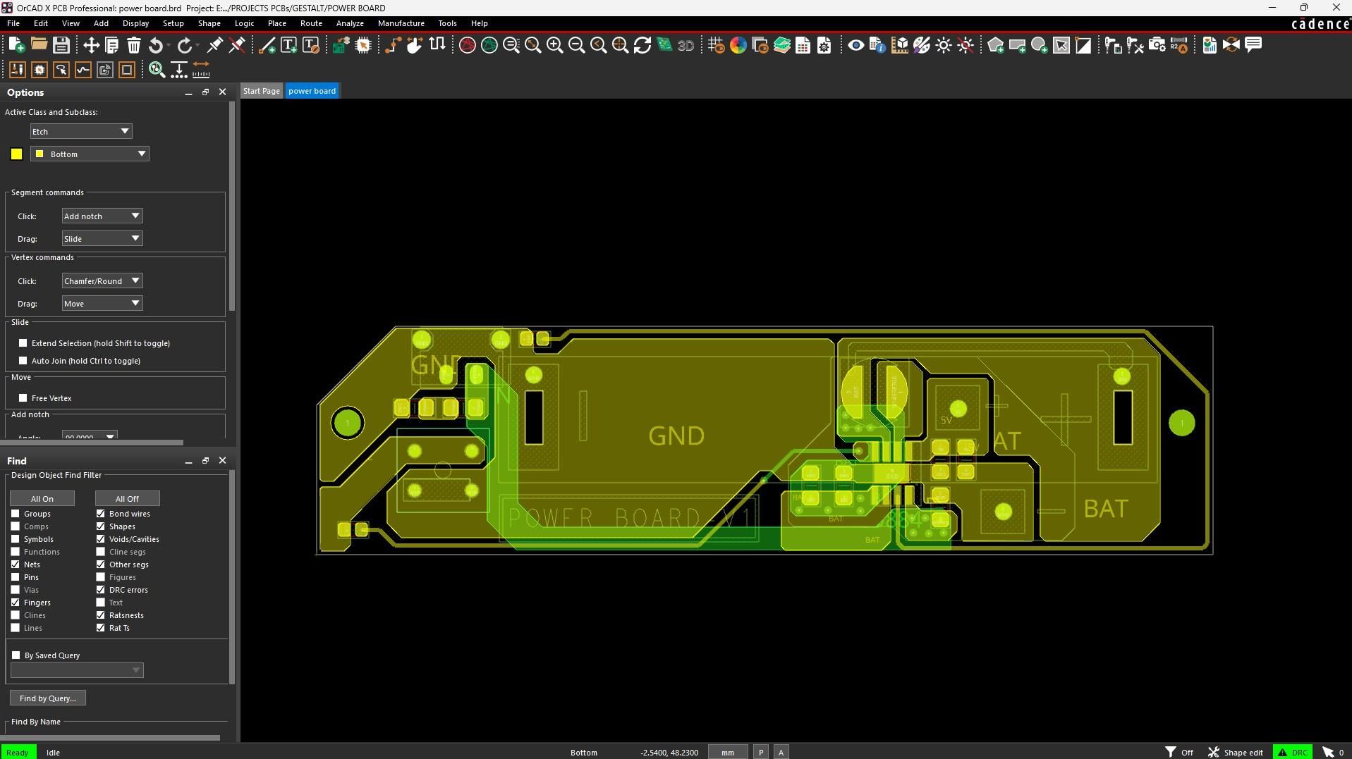
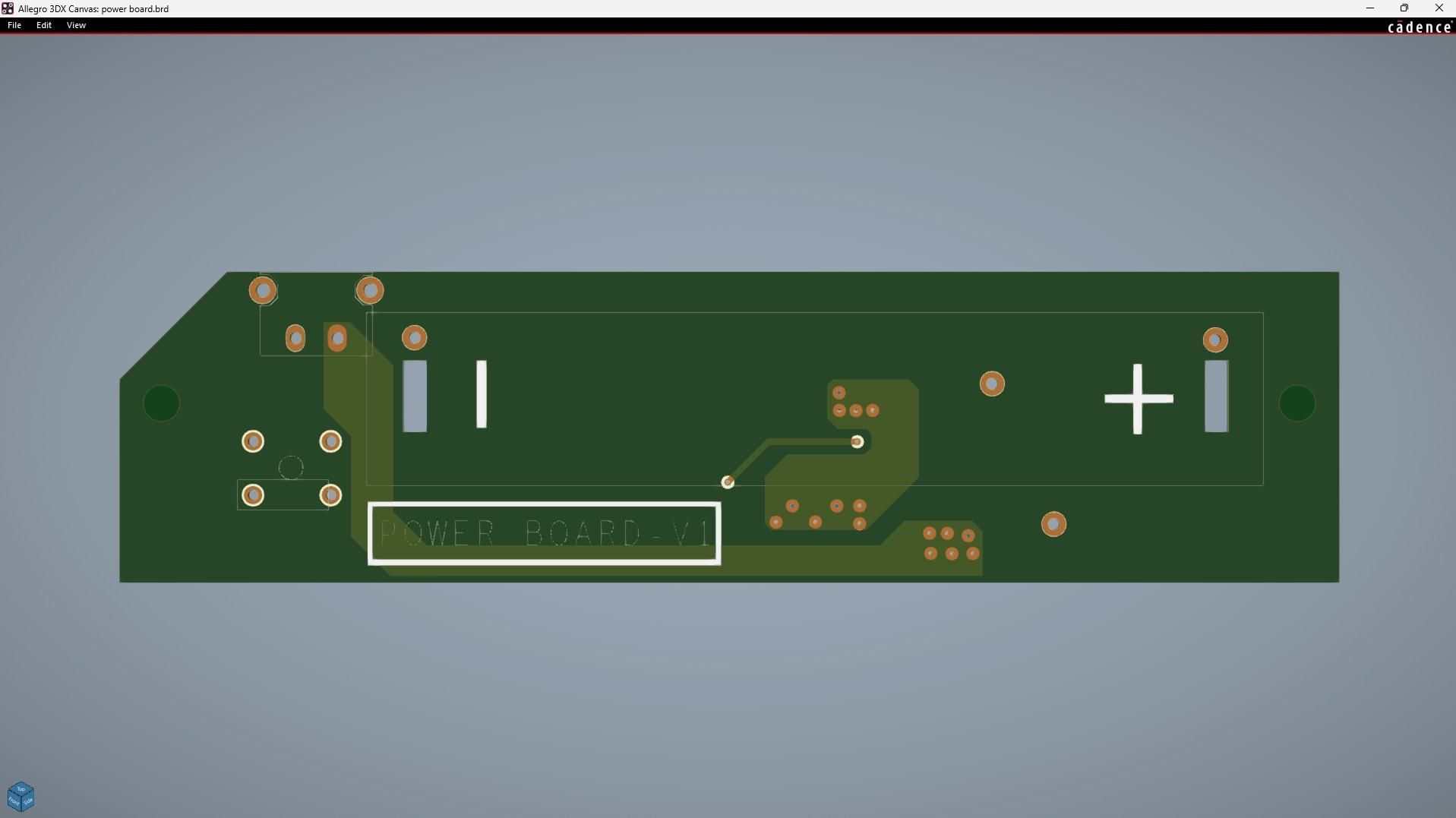
The third PCB used in this project is the Power Board, which serves as the primary power source for the entire system.

A 3.7V Li-ion/Li-Po cell is connected to an IP5306 power management IC, which boosts the battery voltage and provides a stable 5V, 2A output to power both the RGB matrices and the Pico Driver Board.

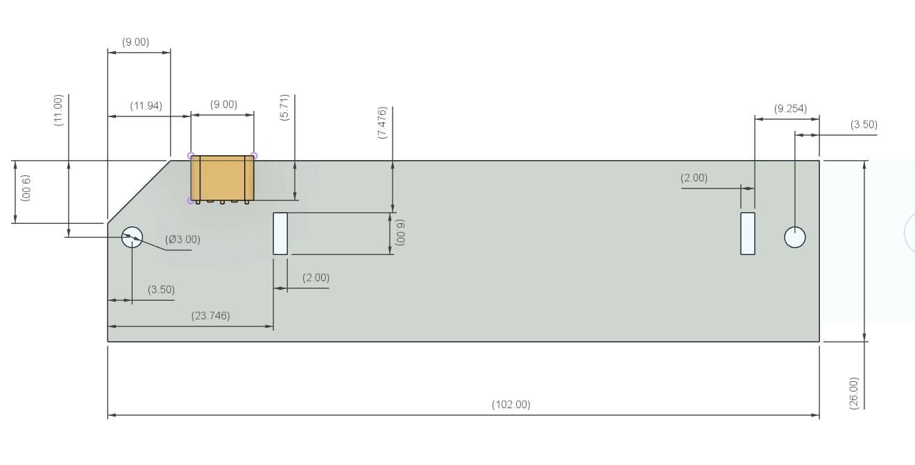
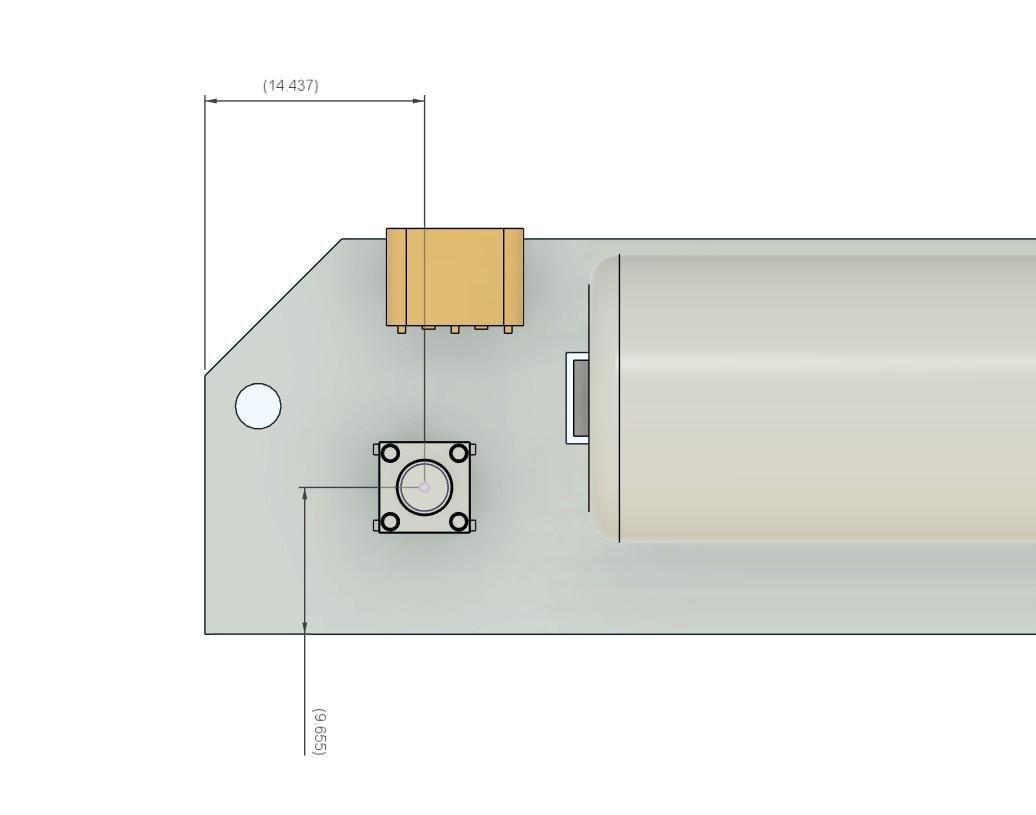
The board also includes a momentary push button connected to the IP5306's KEY pin. Pressing this button enables the output, powering on the entire device. A USB Type-C connector is provided for conveniently charging the battery without opening the enclosure.

Like the previous two PCBs, the board outline was created using the dimensions from the Fusion 360 enclosure model. Once the mechanical constraints were finalized, all the components were placed in position, and the PCB routing was completed.

NextPCB PCB SERVICE
61.gif
Image1.jpg
Image2.jpg
Image3.jpg

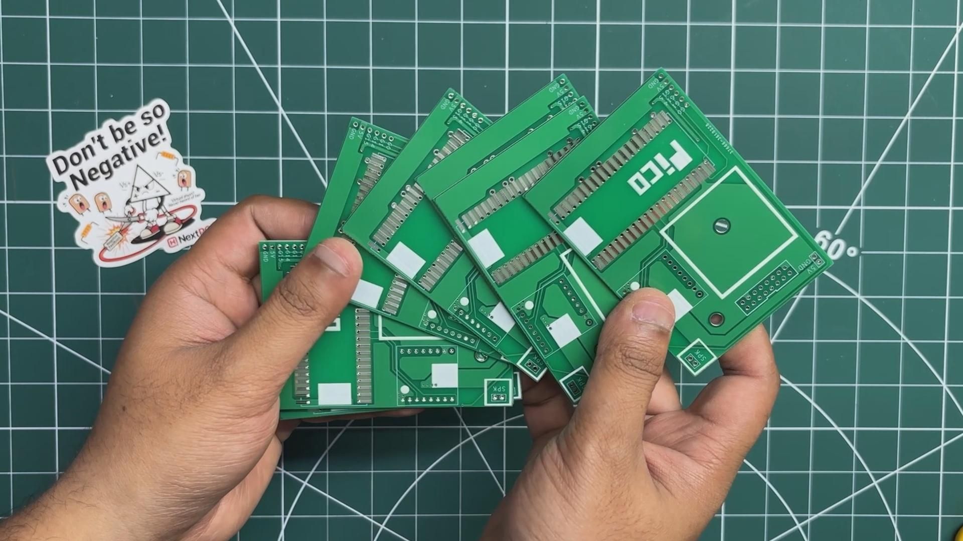
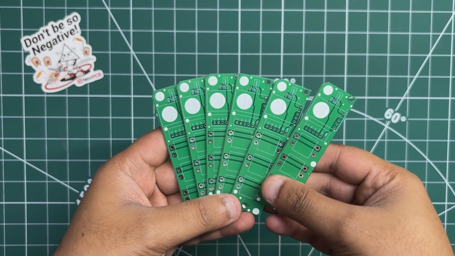
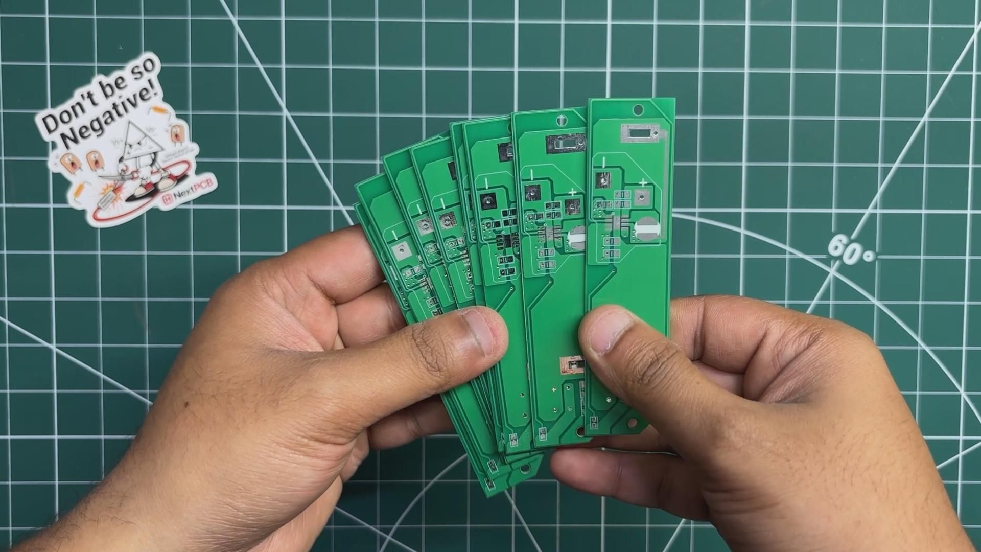
After completing the PCB design, Gerber data for all three PCBs were sent to HQ NextPCB, and an order was placed for Green Solder mask boards with a white silkscreen for all three.

After placing the order, the PCBs were received within a week, and the PCB quality was pretty great.

In addition, I have to bring in HQDFM to you, which has helped me a lot through many projects. Huaqiu’s in-house engineers developed the free Design for Manufacturing software, HQDFM, revolutionizing how PCB designers visualize and verify their designs.

Take advantage of NextPCB's Accelerator campaign and get 2 free assembled RP2040-based PCBs for your innovative projects.

https://www.nextpcb.com/blog/rp2040-free-pcba-prototypes-nextpcb-accelerator

This offer covers all costs, including logistics, making it easier and more affordable to bring your ideas to life. SMT services can be expensive, but NextPCB is here to help you overcome that hurdle. Simply share your relevant project, and they'll take care of the rest. Don't miss out on this amazing opportunity to advance your tech creations!

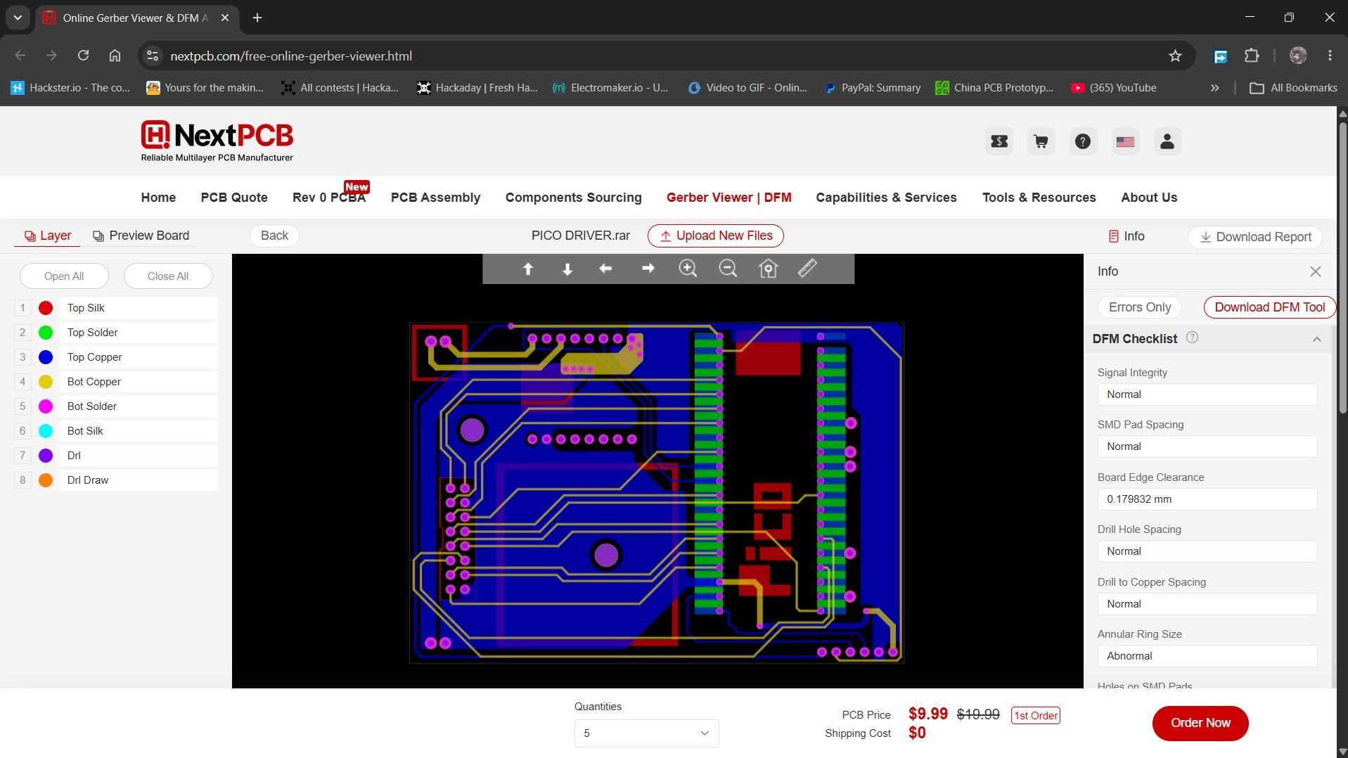
HQDFM: Free Online Gerber Viewer and DFM Analysis Tool
Screenshot 2026-07-14 232159.jpg

Also, NextPCB has its own Gerber Viewer and DFM analysis software.

Your designs are improved by their HQDFM software (DFM) services. Since I find it annoying to wait for DFM reports from manufacturers, HQDFM is the most efficient way to perform a pre-event self-check.

This is what I see in the online Gerber Viewer. It's decent for a quick look, but not entirely clear. For full functionality—like detailed DFM analysis for PCBA—you’ll need to download the desktop software. The web version only offers a basic DFM report.

With comprehensive Design for Manufacture (DFM) analysis features, HQDFM is a free, sophisticated online PCB Gerber file viewer.

With over 15 years of industry experience, it offers valuable insights into advanced manufacturing processes. If you’re looking for reliable PCB services at a budget-friendly price, HQ NextPCB is definitely worth checking out.

PCB ASSEMBLY - PICO DRIVER
02.gif
03.gif
04.gif
05.gif
06.gif
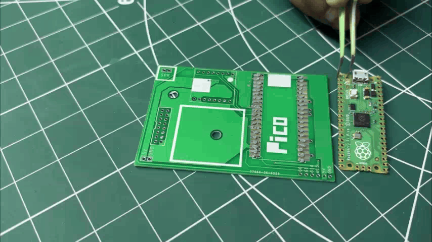
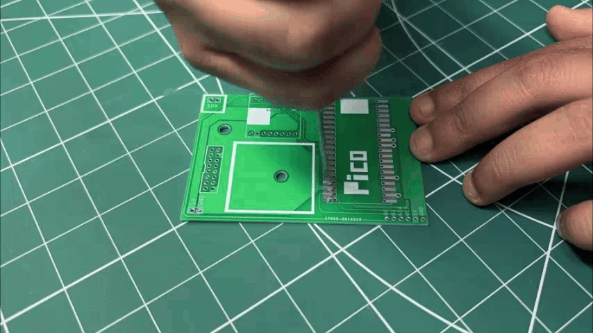
  1. We begin the Pico Driver Board assembly process by applying solder paste to all the Pico pads using a solder paste dispensing needle. Here, we are using Sn/Pb 63/37 solder paste, which has a melting temperature of 200°C.
  2. Next, we pick and place the Raspberry Pi Pico onto the PCB, making sure all of its pins align correctly with the corresponding pads.
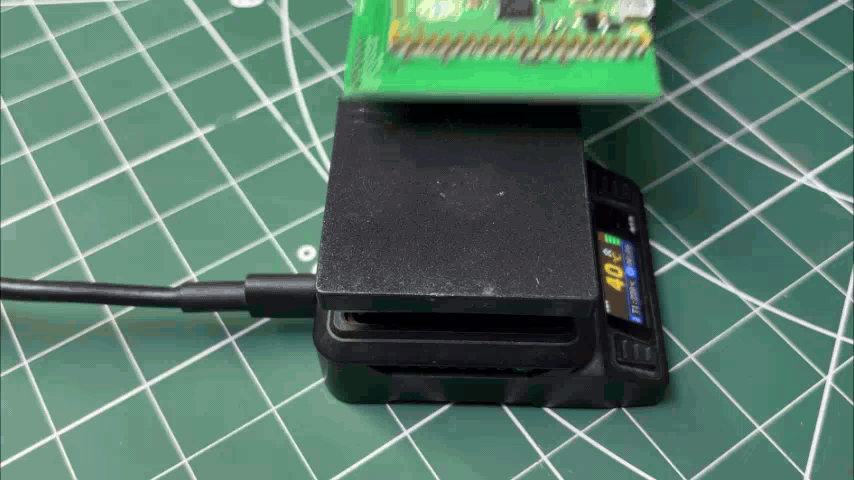
  3. The PCB is then placed on a reflow hotplate. Here, we are using the Miniware MH50, a compact reflow hotplate that is perfect for assembling the Pico Driver Board.
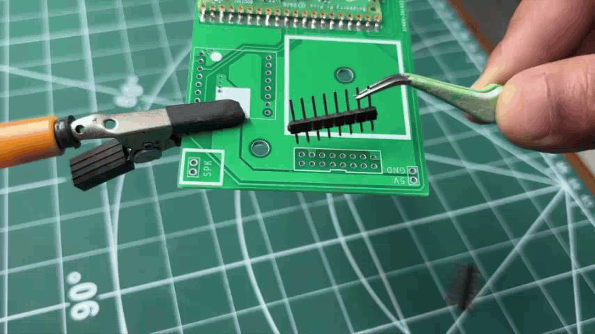
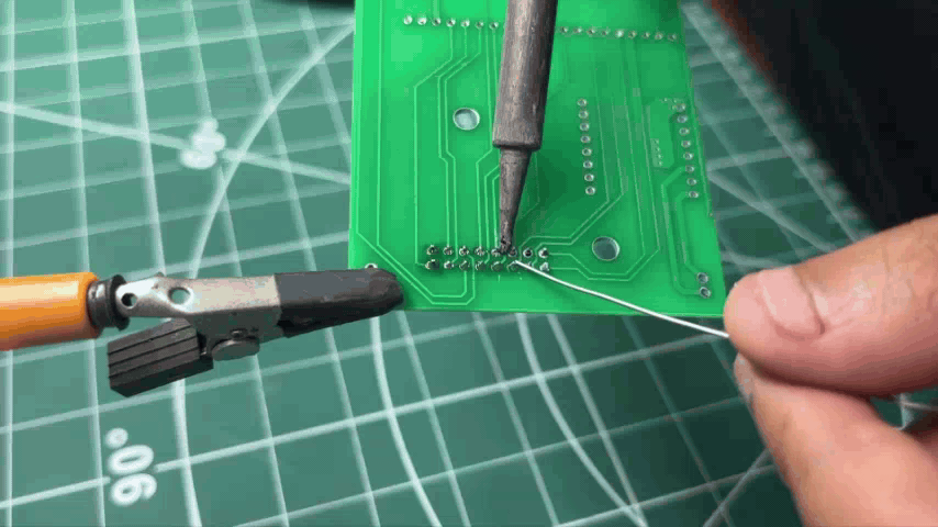
  4. Finally, two CON8 male header connectors are installed on the HUB75 connector pads. We flip the board over and solder the header pins in place using a soldering iron, completing the assembly of the Pico Driver Board.

PCB ASSEMBLY - SWITCH BOARD
15.gif
16.gif
IMG_E0086.JPG
IMG_E0089.JPG
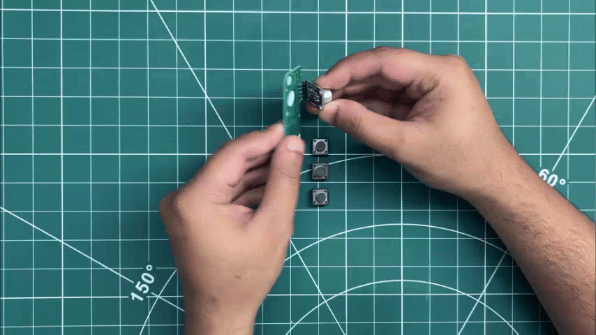
  1. Next comes the PCB assembly process for the Switch Board, which begins by placing the MAX9814 microphone module and all three push buttons in their respective positions.
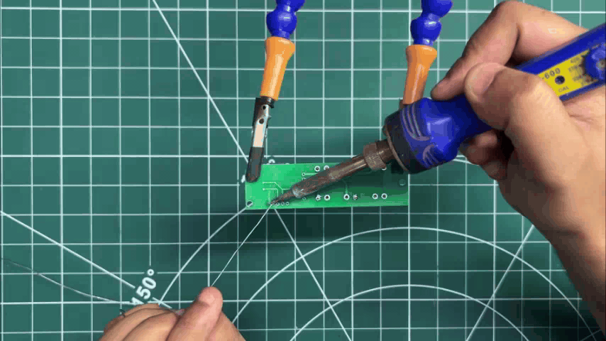
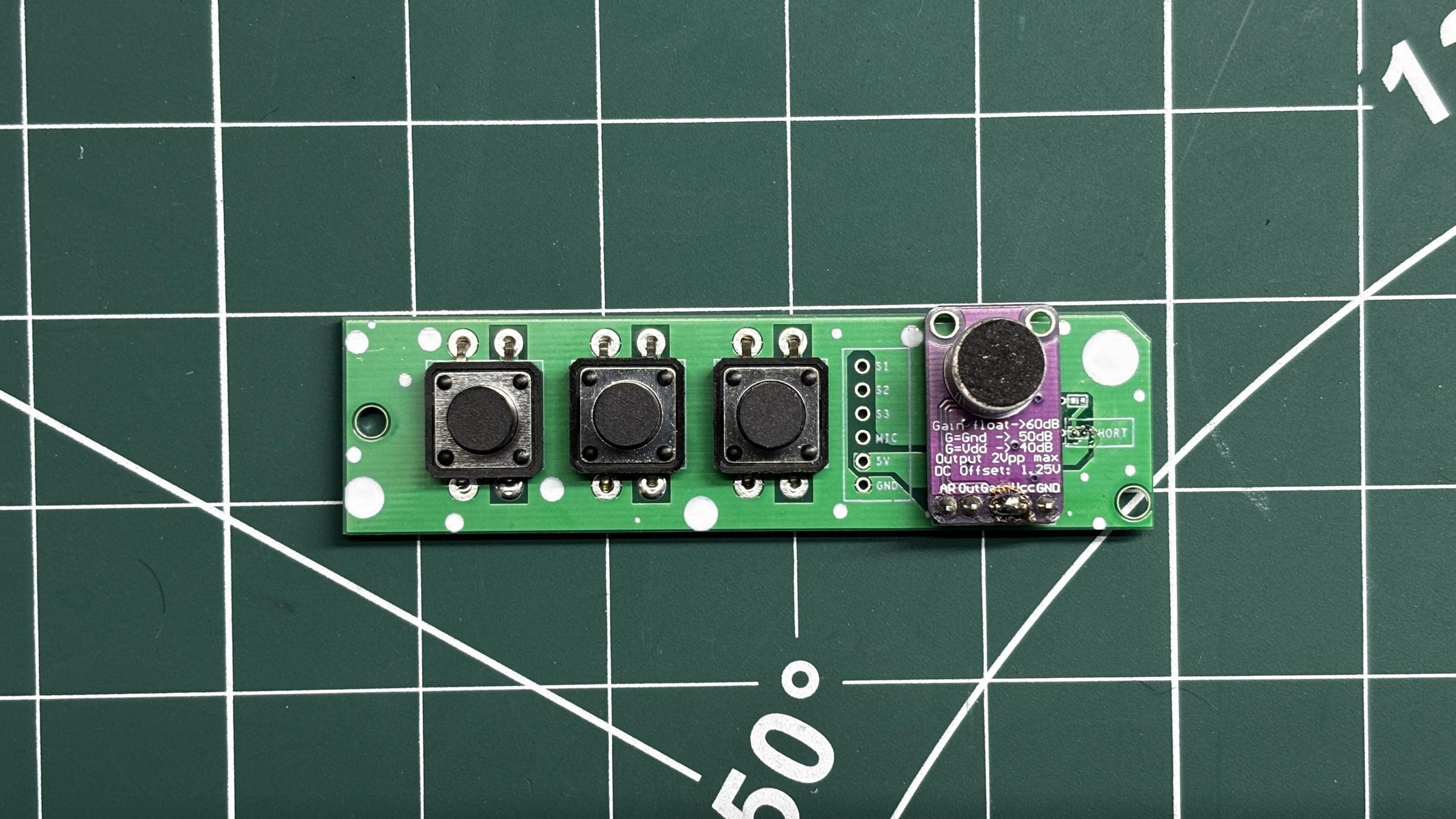
  2. The board is then flipped over, and all the leads are soldered using a soldering iron, securing each component firmly in place.

PCB ASSEMBLY - POWER BOARD
17.gif
18.gif
19.gif
20.gif
21.gif
22.gif
23.gif
24.gif
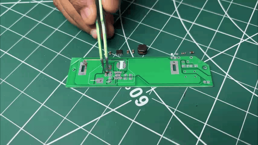
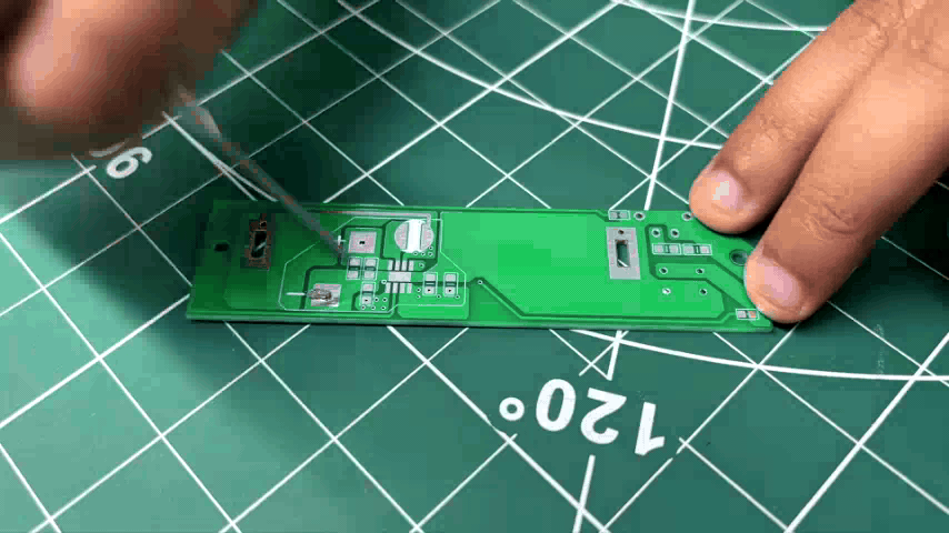
  1. We begin by applying solder paste to all the component pads using the same solder paste dispenser as before.
  2. Next, all the SMD components are picked and placed in their respective positions.
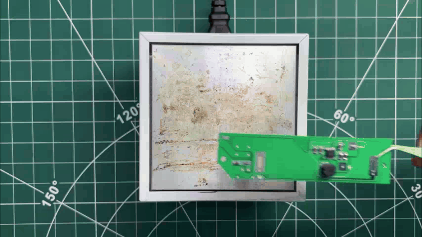
  3. The entire PCB is then placed on a reflow hotplate. This time, we use a slightly larger hotplate since the Power Board is larger than the previous PCBs.
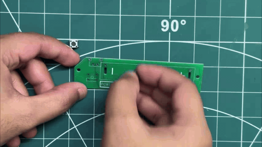
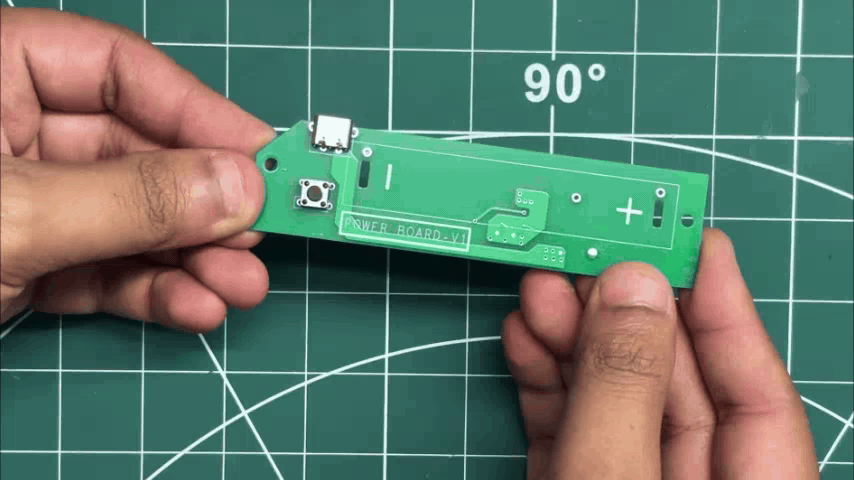
  4. Once the reflow process is complete and all the SMD components are secured, we install the push button, followed by the USB Type-C connector.
  5. The board is then flipped over, and the leads of the through-hole components are soldered using a soldering iron, securing them in place.
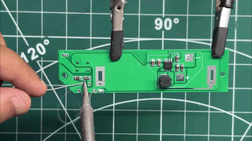
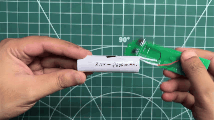
  6. Next, we connect the positive terminal of a 3.7V, 2600mAh lithium-ion cell to the B+ terminal of the Power Board and the negative terminal to the B- terminal using a soldering iron.

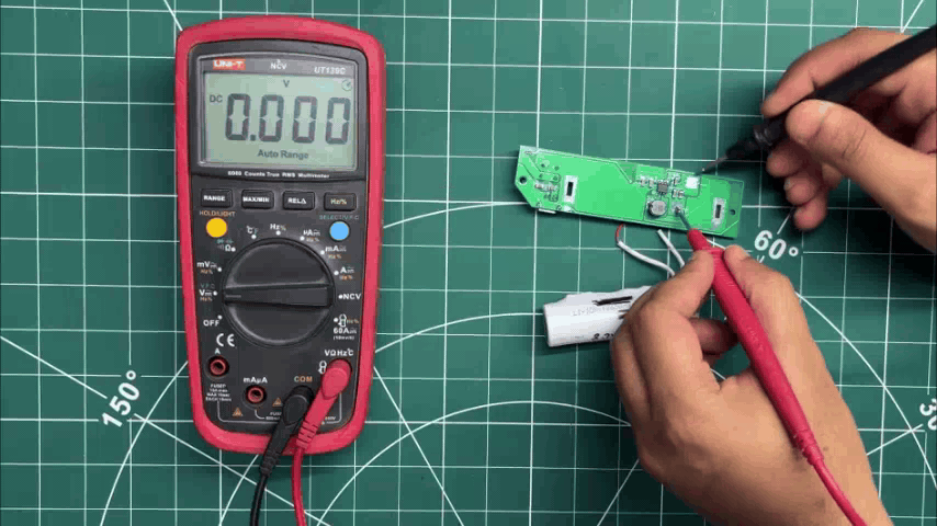
To verify that everything is working correctly, we press the power button. The status LED lights up, indicating that the board has powered on. We then use a multimeter to measure the output voltage and obtain a stable 5V, confirming that the Power Board is functioning as expected.

PICO DRIVER & MATRIX ASSEMBLY
07.gif
08.gif
IMG_E0070.JPG
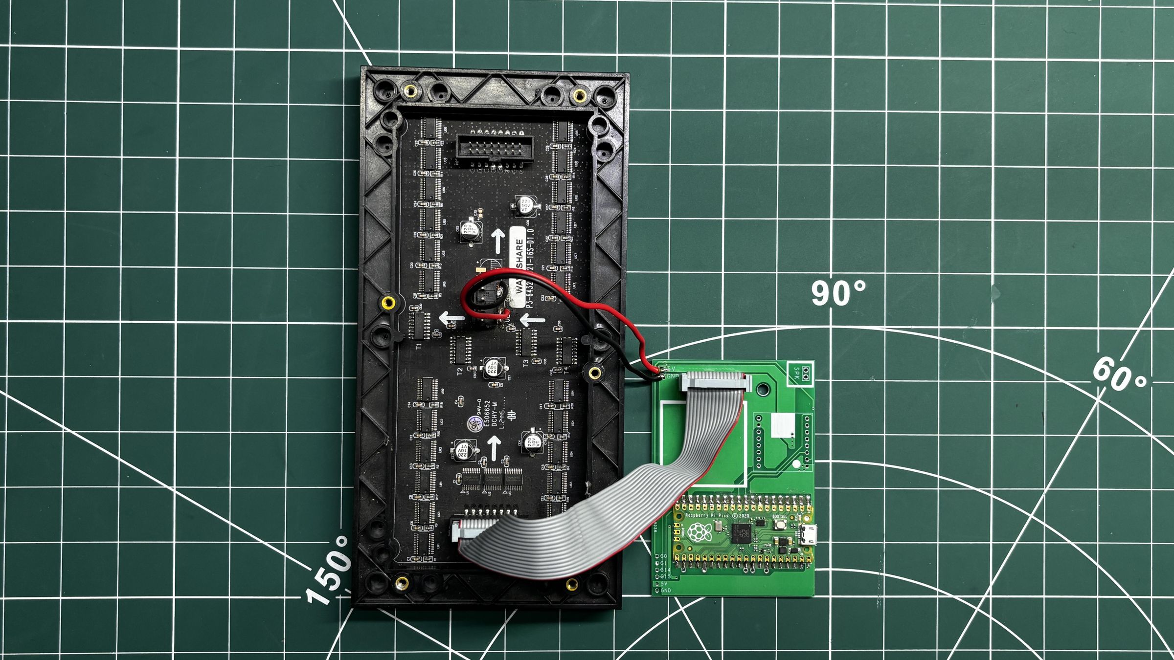
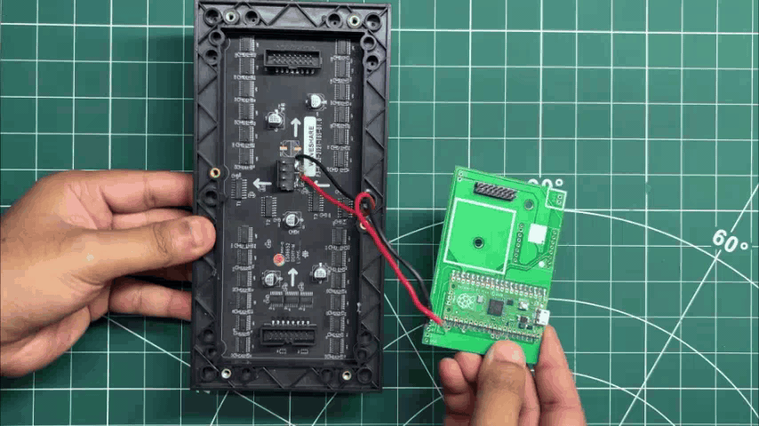
  1. We begin by connecting the VCC and GND terminals of the RGB matrix to the 5V and GND outputs of the Pico Driver Board using a soldering iron.
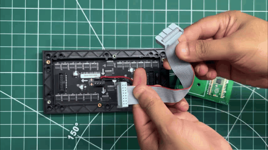
  2. Next, we connect the matrix's HUB75 interface to the CON16 connector on the Pico Driver Board using a 16-pin ribbon cable.

MATRIX DEMO
Matrix 63x32 P4 Single Panel DEMO
09.gif
IMG_E0074.JPG

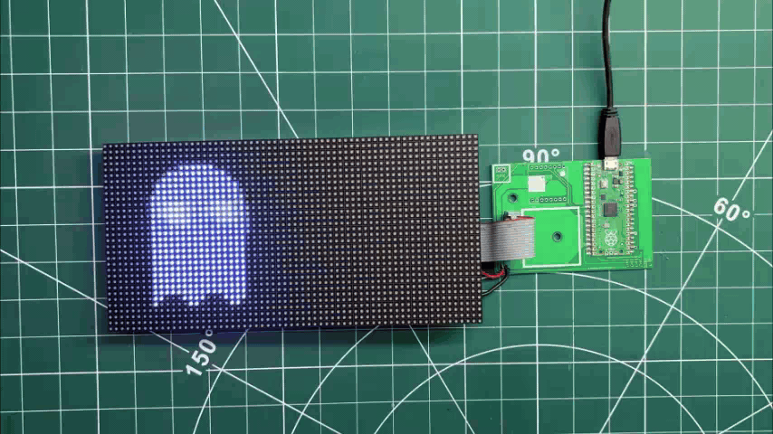
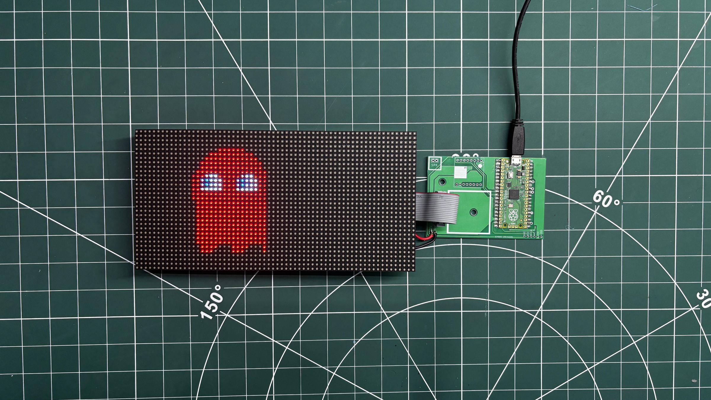
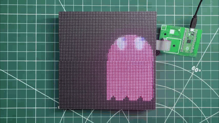
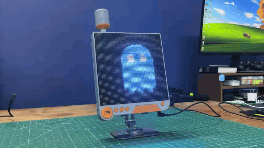
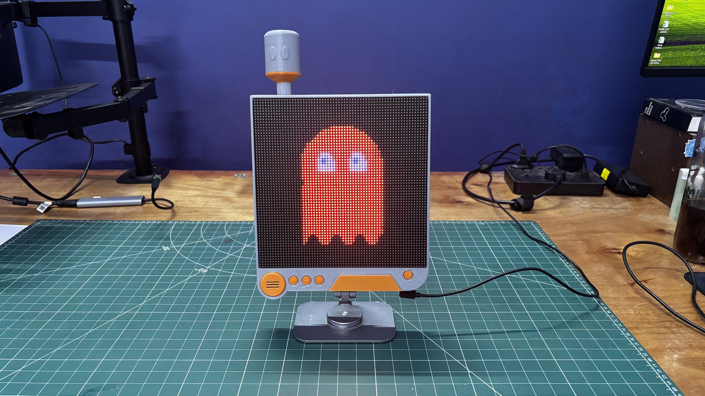
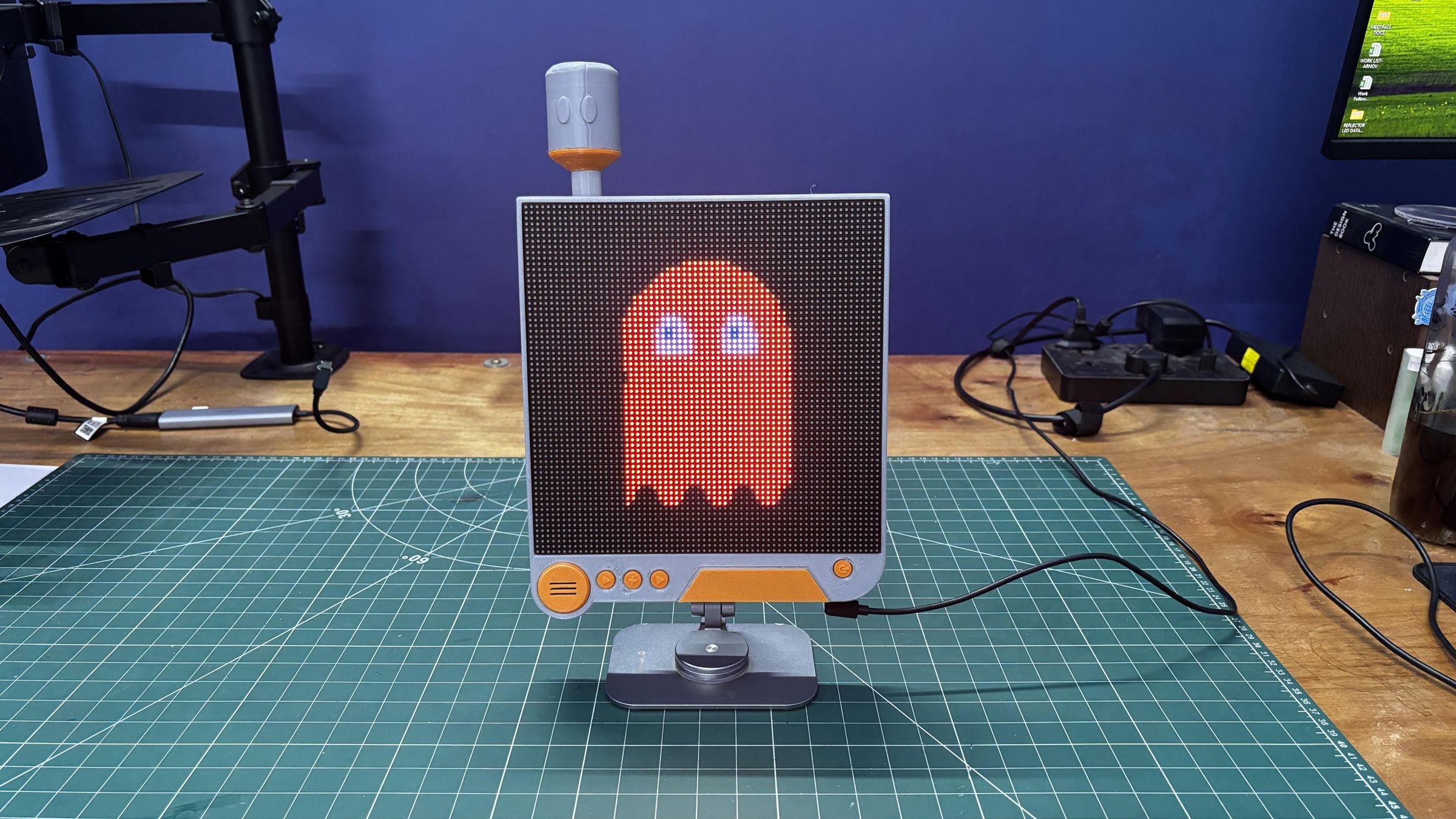
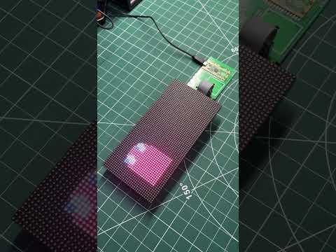
We then upload the demo code below, which displays Cyber Ghost, a Pac-Man-inspired ghost featuring animated feet and continuously shifting RGB colors.

Here's the complete code.

#include <Adafruit_Protomatter.h>
#include <math.h>

// ── Pins (Raspberry Pi Pico GPIO) ─────────────────────────────────
#define R1 2
#define G1 3
#define B1 4
#define R2 5
#define G2 6 // Using GPIO 6
#define B2 9
#define PIN_A 10
#define PIN_B 16
#define PIN_C 18
#define PIN_D 20
#define CLK 11
#define LAT 12
#define OE 13

// ── Resolution for a SINGLE 64x32 Panel ───────────────────────────
#define W 64
#define H 32

uint8_t rgbPins[] = { R1, G1, B1, R2, G2, B2 };
uint8_t addrPins[] = { PIN_A, PIN_B, PIN_C, PIN_D };

// ── Constructor ───────────────────────────────────────────────────
// Bit Depth = 3 (Maximum refresh speed, zero flicker!)
// Double Buffer = true
// Tiling = 1 (Single matrix)
Adafruit_Protomatter matrix(
W, 3, 1, rgbPins,
4, addrPins,
CLK, LAT, OE,
true,
1
);

// ── Global Variables & Timing ─────────────────────────────────────
uint32_t frameCount = 0;
float ghostHue = 360.0f; // Start at Red (360 degrees)

// Fast RGB565 color helper
inline uint16_t rgb(uint8_t r, uint8_t g, uint8_t b) {
return matrix.color565(r, g, b);
}

// ── Smooth HSV to RGB Converter ───────────────────────────────────
// Translates a Hue angle (0.0 to 360.0) into a smooth RGB565 color.
// Decrementing the hue cycles: Red -> Blue -> Green -> Red
uint16_t getSmoothHue(float h) {
while (h < 0.0f) h += 360.0f;
while (h >= 360.0f) h -= 360.0f;
float c = 1.0f; // Full saturation & value
float x = c * (1.0f - fabsf(fmodf(h / 60.0f, 2.0f) - 1.0f));
float r = 0, g = 0, b = 0;
if (h < 60) { r = c; g = x; b = 0; }
else if (h < 120) { r = x; g = c; b = 0; }
else if (h < 180) { r = 0; g = c; b = x; }
else if (h < 240) { r = 0; g = x; b = c; }
else if (h < 300) { r = x; g = 0; b = c; }
else { r = c; g = 0; b = x; }

return rgb((uint8_t)(r * 255), (uint8_t)(g * 255), (uint8_t)(b * 255));
}

// ══════════════════════════════════════════════════════════════════
// SCENE: Scaled Rainbow Cyber-Ghost (Smooth Sine Physics for 64x32)
// ══════════════════════════════════════════════════════════════════
void drawPacGhost() {
matrix.fillScreen(0);
float t = frameCount * 0.06f;
// 1. Color Evolution: Smoothly rotate hue backwards (Red -> Blue -> Green -> Red)
ghostHue -= 0.6f; // Adjust this number to make the color cycle faster or slower!
if (ghostHue < 0.0f) ghostHue += 360.0f;
uint16_t GHOST_COLOR = getSmoothHue(ghostHue);
uint16_t EYE_WHITE = rgb(240, 240, 240);
uint16_t PUPIL_BLUE = rgb(0, 50, 255);
// 2. Spatial Movement: Center X drifts side to side, Center Y hovers gently
float base_cx = 32.0f + sinf(t * 1.2f) * 18.0f;
float hover_y = sinf(t * 3.0f) * 1.5f;
// Render body bounding box tailored for 32px height
for (int y = 4; y < 28; y++) {
for (int x = base_cx - 10; x < base_cx + 10; x++) {
if(x < 0 || x >= W || y < 0 || y >= H) continue;

float relX = x - base_cx;
float relY = (y - 5) + hover_y;

float headRadius = 8.0f;
float bodyHeight = 12.0f;
bool drawPixel = false;
// Semi-circular dome head
if (relY < headRadius) {
float dx = relX;
float dy = relY - headRadius;
if (sqrtf(dx*dx + dy*dy) < headRadius) {
drawPixel = true;
}
}
// Solid mid-body
else if (relY >= headRadius && relY < bodyHeight + headRadius) {
if (relX >= -8.0f && relX <= 8.0f) {
drawPixel = true;
}
}
// Animated rippling feet
else if (relY >= bodyHeight + headRadius) {
float footRipple = 1.5f * sinf(relX * 0.9f - t * 4.0f);
if (relY < (bodyHeight + headRadius + 3.0f + footRipple) && relX >= -8.0f && relX <= 8.0f) {
drawPixel = true;
}
}
if (drawPixel) {
matrix.drawPixel(x, y, GHOST_COLOR);
}
}
}
// 3. Dynamic Eye Tracking
float lookX = sinf(t * 1.2f) * 2.0f;
float lookY = cosf(t * 1.5f) * 1.0f;
auto drawEye = [&](float ex, float ey) {
for (int y = ey - 3; y < ey + 3; y++) {
for (int x = ex - 2; x < ex + 2; x++) {
if(x < 0 || x >= W || y < 0 || y >= H) continue;
float dx = x - ex;
float dy = y - (ey + hover_y);
if((dx*dx / 4.0f) + (dy*dy / 9.0f) < 1.0f) {
matrix.drawPixel(x, y, EYE_WHITE);
}
}
}
// Blue Pupils
int px = ex + lookX;
int py = (ey + hover_y) + lookY;
matrix.fillRect(px, py, 2, 2, PUPIL_BLUE);
};

drawEye(base_cx - 4.0f, 11.0f);
drawEye(base_cx + 4.0f, 11.0f);
}

// ── Setup & Loop ───────────────────────────────────────────────────
void setup() {
Serial.begin(115200);
ProtomatterStatus s = matrix.begin();
if (s != PROTOMATTER_OK) {
Serial.print("Protomatter Init Error: ");
Serial.println((int)s);
while(1);
}
}

void loop() {
drawPacGhost();
matrix.show();
frameCount++;
// 15ms delay yields a rock-solid ~60 FPS animation loop
delay(15);
}

DUAL MATRIX ASSEMBLY

11.gif
12.gif

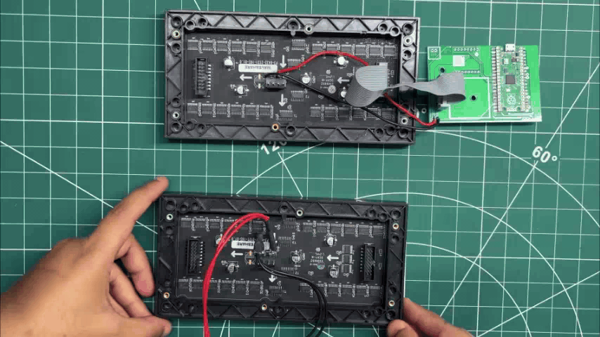
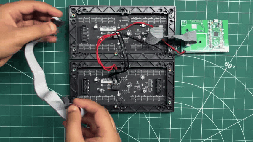
After testing the single-matrix setup, we added the second RGB matrix by connecting its VCC and GND lines in parallel with those of the first matrix.

Next, we used a slightly longer 16-pin ribbon cable to connect the HUB75 DOUT connector of the first matrix to the HUB75 DIN connector of the second matrix. This daisy-chains the two 64×32 matrices together, allowing them to operate as a single 64×64 RGB matrix display.

DUAL MATRIX DEMO
Matrix 63x32 P4 Dual Panel DEMO
13.gif

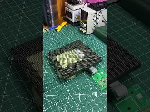
Just like the single-matrix demo code, we prepared the same Cyber-Ghost animation for the dual-matrix setup, which has a total resolution of 64×64 pixels.

We uploaded the code below to the Raspberry Pi Pico, and the setup worked perfectly, with both RGB matrix operating together as a single 64×64 display.

Updated Code

#include <Adafruit_Protomatter.h>
#include <math.h>

// ── Pins (Raspberry Pi Pico GPIO) ─────────────────────────────────
#define R1 2
#define G1 3
#define B1 4
#define R2 5
#define G2 6 // Confirmed GPIO 6
#define B2 9
#define PIN_A 10
#define PIN_B 16
#define PIN_C 18
#define PIN_D 20
#define CLK 11
#define LAT 12
#define OE 13

// ── Resolution for TWO Chained 64x32 Panels (64x64 total) ─────────
#define W 64
#define H 64

uint8_t rgbPins[] = { R1, G1, B1, R2, G2, B2 };
uint8_t addrPins[] = { PIN_A, PIN_B, PIN_C, PIN_D };

// ── Constructor ───────────────────────────────────────────────────
// Bit Depth = 3 (Maximum refresh speed, zero flicker!)
// Double Buffer = true
// Tiling = 2 (Change to -2 if your second chained panel displays upside down)
Adafruit_Protomatter matrix(
W, 3, 1, rgbPins,
4, addrPins,
CLK, LAT, OE,
true,
2
);

// ── Global Variables & Timing ─────────────────────────────────────
uint32_t frameCount = 0;

// Fast RGB565 color helper
inline uint16_t rgb(uint8_t r, uint8_t g, uint8_t b) {
return matrix.color565(r, g, b);
}

// ══════════════════════════════════════════════════════════════════
// SCENE: Scaled Rainbow Cyber-Ghost (Smooth Sine Physics for 64x64)
// ══════════════════════════════════════════════════════════════════
void drawPacGhost() {
matrix.fillScreen(0);
float t = frameCount * 0.05f;
// ── Blazing-Fast Integer Color Cycle: Red -> Purple -> Blue -> Green -> Red ──
// Using pure 8-bit integer math prevents CPU float stalling and eliminates top-to-bottom scan lag!
uint8_t wheelPos = (frameCount >> 1) & 0xFF; // Change (>> 1) to (>> 2) for a slower color transition
uint8_t r, g, b;
if (wheelPos < 85) {
r = 255 - wheelPos * 3;
g = 0;
b = wheelPos * 3;
} else if (wheelPos < 170) {
wheelPos -= 85;
r = 0;
g = wheelPos * 3;
b = 255 - wheelPos * 3;
} else {
wheelPos -= 170;
r = wheelPos * 3;
g = 255 - wheelPos * 3;
b = 0;
}
uint16_t GHOST_COLOR = rgb(r, g, b);
uint16_t EYE_WHITE = rgb(240, 240, 240);
uint16_t PUPIL_BLUE = rgb(0, 50, 255);
// ── Spatial Movement: Center X drifts side to side, Center Y hovers gently ──
float base_cx = 32.0f + sinf(t * 1.2f) * 16.0f;
float hover_y = sinf(t * 3.0f) * 2.5f;
// Render body bounding box scaled specifically for the 64px vertical canvas
for (int y = 8; y < 58; y++) {
for (int x = base_cx - 18; x < base_cx + 18; x++) {
if(x < 0 || x >= W || y < 0 || y >= H) continue;

float relX = x - base_cx;
float relY = (y - 12) + hover_y;

// Upscaled proportions to fill the 64x64 grid
float headRadius = 15.0f;
float bodyHeight = 24.0f;
bool drawPixel = false;
// 1. Semi-circular dome head
if (relY < headRadius) {
float dx = relX;
float dy = relY - headRadius;
if (sqrtf(dx*dx + dy*dy) < headRadius) {
drawPixel = true;
}
}
// 2. Solid mid-body
else if (relY >= headRadius && relY < bodyHeight + headRadius) {
if (relX >= -15.0f && relX <= 15.0f) {
drawPixel = true;
}
}
// 3. Animated rippling feet (fluid sinusoidal waves across the bottom edge)
else if (relY >= bodyHeight + headRadius) {
float footRipple = 2.5f * sinf(relX * 0.7f - t * 4.0f);
if (relY < (bodyHeight + headRadius + 4.0f + footRipple) && relX >= -15.0f && relX <= 15.0f) {
drawPixel = true;
}
}
if (drawPixel) {
matrix.drawPixel(x, y, GHOST_COLOR);
}
}
}
// ── Dynamic Eye Tracking (Eyes shift naturally as the ghost moves) ──
float lookX = sinf(t * 1.2f) * 3.0f;
float lookY = cosf(t * 1.5f) * 1.5f;
auto drawEye = [&](float ex, float ey) {
// Large vertical oval eyes (6x10 pixels)
for (int y = ey - 5; y < ey + 5; y++) {
for (int x = ex - 3; x < ex + 3; x++) {
if(x < 0 || x >= W || y < 0 || y >= H) continue;
float dx = x - ex;
float dy = y - (ey + hover_y);
if((dx*dx / 9.0f) + (dy*dy / 25.0f) < 1.0f) {
matrix.drawPixel(x, y, EYE_WHITE);
}
}
}
// 2x2 Blue Pupils
int px = ex + lookX;
int py = (ey + hover_y) + lookY;
matrix.fillRect(px - 1, py - 1, 2, 2, PUPIL_BLUE);
};

// Position left and right eyes symmetrically on the larger head
drawEye(base_cx - 6.0f, 22.0f);
drawEye(base_cx + 6.0f, 22.0f);
}

// ── Setup & Loop ───────────────────────────────────────────────────
void setup() {
Serial.begin(115200);
ProtomatterStatus s = matrix.begin();
if (s != PROTOMATTER_OK) {
Serial.print("Protomatter Init Error: ");
Serial.println((int)s);
while(1);
}
}

void loop() {
drawPacGhost();
matrix.show();
frameCount++;
// 15ms delay yields a rock-solid ~60 FPS animation loop
delay(15);
}

WIRING - PICO DRIVER & SWITCH BOARD

25.gif
IMG_E0109.JPG
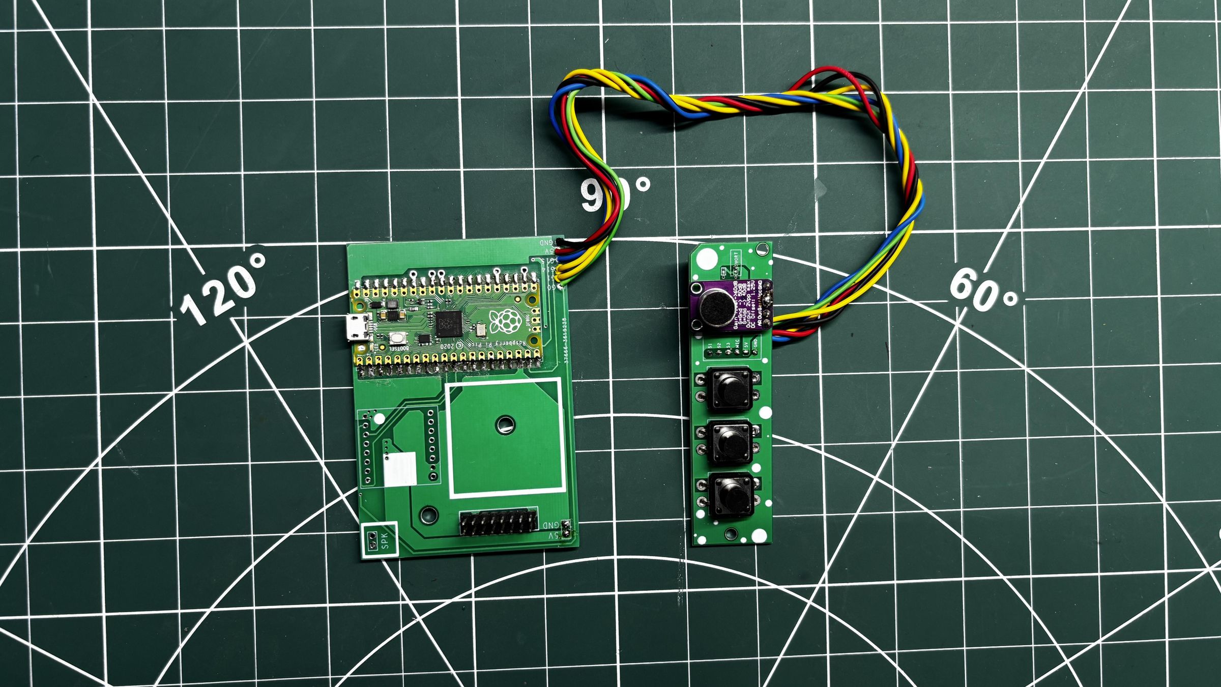
  1. The Pico Driver Board is first disconnected from the RGB matrix and connected to the Switch Board.
  2. We begin by connecting the GND of the Pico Driver Board to the GND of the Switch Board, followed by connecting the 5V output of the Pico Driver Board to the VCC input of the Switch Board.
  3. Next, Switch 1 (PREV) is connected to GPIO0, Switch 2 (NEXT) is connected to GPIO14, and Switch 3 (WAVEFORM MODE) is connected to GPIO1. Finally, the microphone output pin on the Switch Board is connected to GPIO28 of the Pico.

For all these connections, we use single-core silver-plated copper wire.

WIRING - PICO DRIVER SWITCH BOARD WITH POWER BOARD
35.gif

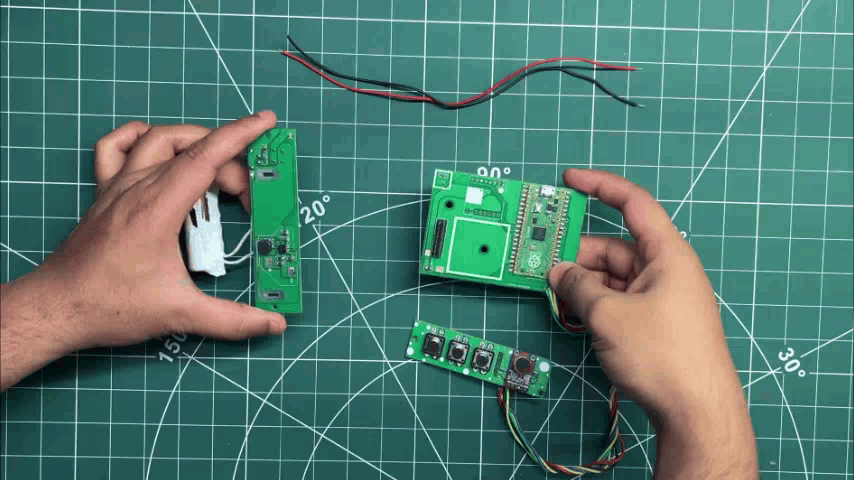
The 5V and GND outputs of the Power Board are connected to the 5V and GND terminals of the Pico Driver Board using two connecting wires.

CODE

Before beginning the matrix assembly process, I uploaded the main code below into the raspbeery pi pico.

#include <Adafruit_Protomatter.h>
#include <math.h>

// ── Pins (Raspberry Pi Pico GPIO) ─────────────────────────────────
#define R1 2
#define G1 3
#define B1 4
#define R2 5
#define G2 6
#define B2 9
#define PIN_A 10
#define PIN_B 16
#define PIN_C 18
#define PIN_D 20
#define CLK 11
#define LAT 12
#define OE 13

// ── Buttons ───────────────────────────────────────────────────────
#define BTN_PREV 0
#define BTN_NEXT 14
#define BTN_WAVE 1

// ── Resolution for TWO Chained 64x32 Panels (64x64 total) ─────────
#define W 64
#define H 64

uint8_t rgbPins[] = { R1, G1, B1, R2, G2, B2 };
uint8_t addrPins[] = { PIN_A, PIN_B, PIN_C, PIN_D };

Adafruit_Protomatter matrix(
W, 3, 1, rgbPins, 4, addrPins, CLK, LAT, OE, true, 2
);

// ── Global Variables & Timing ─────────────────────────────────────
uint32_t frameCount = 0;
int currentAnim = 0;
const int NUM_ANIMS = 9;

unsigned long previousMillis = 0;
const int frameInterval = 16;

bool lastBtnPrev = HIGH;
bool lastBtnNext = HIGH;
bool lastBtnWave = HIGH;
unsigned long lastDebounceTime = 0;
const unsigned long debounceDelay = 50;

// ── Audio / Waveform Settings ─────────────────────────────────────
const int MIC_PIN = 28; // Using GPIO 28 (ADC2)
const int OVERSAMP = 128;
const int X_STEP = 2;
const int NUM_POINTS = W / X_STEP;
const float MAX_WAVE_FRACTION = 0.5f;

float rmsPeak = 200.0f;
float loudSmooth = 0.0f;
bool noiseInit = false;
float noiseFloor = 100.0f;
const float LOUD_GATE = 0.08f;

float waveY[NUM_POINTS];
bool waveMode = false;

inline uint16_t rgb(uint8_t r, uint8_t g, uint8_t b) {
return matrix.color565(r, g, b);
}

// ══════════════════════════════════════════════════════════════════
// ANIMATION 0: The Original Cyber-Ghost
// ══════════════════════════════════════════════════════════════════
void drawPacGhost() {
matrix.fillScreen(0);
float t = frameCount * 0.05f;
uint8_t wheelPos = (frameCount >> 1) & 0xFF;
uint8_t r, g, b;
if (wheelPos < 85) { r = 255 - wheelPos * 3; g = 0; b = wheelPos * 3; }
else if (wheelPos < 170) { wheelPos -= 85; r = 0; g = wheelPos * 3; b = 255 - wheelPos * 3; }
else { wheelPos -= 170; r = wheelPos * 3; g = 255 - wheelPos * 3; b = 0; }
uint16_t GHOST_COLOR = rgb(r, g, b);
float base_cx = 32.0f + sinf(t * 1.2f) * 16.0f;
float hover_y = sinf(t * 3.0f) * 2.5f;
for (int y = 8; y < 58; y++) {
for (int x = base_cx - 18; x < base_cx + 18; x++) {
if(x < 0 || x >= W || y < 0 || y >= H) continue;
float relX = x - base_cx; float relY = (y - 12) + hover_y;
bool drawPixel = false;
if (relY < 15.0f) {
if (sqrtf(relX*relX + (relY - 15.0f)*(relY - 15.0f)) < 15.0f) drawPixel = true;
} else if (relY >= 15.0f && relY < 39.0f) {
if (relX >= -15.0f && relX <= 15.0f) drawPixel = true;
} else if (relY >= 39.0f) {
float footRipple = 2.5f * sinf(relX * 0.7f - t * 4.0f);
if (relY < (43.0f + footRipple) && relX >= -15.0f && relX <= 15.0f) drawPixel = true;
}
if (drawPixel) matrix.drawPixel(x, y, GHOST_COLOR);
}
}
float lookX = sinf(t * 1.2f) * 3.0f; float lookY = cosf(t * 1.5f) * 1.5f;
auto drawEye = [&](float ex, float ey) {
for (int y = ey - 5; y < ey + 5; y++) {
for (int x = ex - 3; x < ex + 3; x++) {
if(x < 0 || x >= W || y < 0 || y >= H) continue;
float dx = x - ex; float dy = y - (ey + hover_y);
if((dx*dx / 9.0f) + (dy*dy / 25.0f) < 1.0f) matrix.drawPixel(x, y, rgb(240, 240, 240));
}
}
matrix.fillRect(ex + lookX - 1, (ey + hover_y) + lookY - 1, 2, 2, rgb(0, 50, 255));
};
drawEye(base_cx - 6.0f, 22.0f); drawEye(base_cx + 6.0f, 22.0f);
}

// ══════════════════════════════════════════════════════════════════
// ANIMATION 1: Cyberpunk 2077 Relic Glitch
// ══════════════════════════════════════════════════════════════════
void drawCyberpunkRelic() {
matrix.fillScreen(rgb(10, 0, 15)); // Dark corporate background
uint16_t neonCyan = rgb(0, 255, 255);
uint16_t neonYellow = rgb(255, 240, 0);
uint16_t neonRed = rgb(255, 0, 50);

// Intentional X-axis tearing/glitching for the entire logo
int glitchX = (random(100) > 85) ? random(-6, 6) : 0;
// Base coordinates for the logo
int x = 16 + glitchX;
int y = 8;

// ── Draw the Custom Relic Logo Geometry ──
// Outer Frame
matrix.fillRect(x, y, 32, 6, neonRed); // Top horizontal
matrix.fillRect(x + 26, y, 6, 32, neonRed); // Right vertical
matrix.fillRect(x + 14, y + 26, 18, 6, neonRed); // Bottom horizontal (partial)
matrix.fillRect(x, y, 6, 22, neonRed); // Left vertical
// Inner 'R' Mechanism
matrix.fillRect(x, y + 12, 16, 6, neonRed); // Middle horizontal
matrix.fillRect(x + 14, y + 12, 6, 9, neonRed); // Inner right vertical
// The iconic 45-degree angle cut
matrix.fillRect(x, y + 22, 10, 6, neonRed); // Bottom-left inward turn
for(int i = 0; i < 6; i++) {
matrix.drawLine(x + 8 + i, y + 27, x + 16 + i, y + 19, neonRed); // Thick diagonal line
}

// Draw "RELIC" Text below the logo
matrix.setCursor(17 + glitchX, 44);
matrix.setTextColor(neonRed);
matrix.print("RELIC");

// Glitching core data block inside the logo
matrix.fillRect(x + 12, y + 16, 4, 4, neonYellow);

// ── Glitch & Artifact Effects ──
// Digital barcode / hacking lines cutting across
for(int i = 0; i < 7; i++) {
int lineY = random(0, 64);
matrix.drawFastHLine(random(0, 32), lineY, random(10, 45), neonCyan);
}
// Occasional full-screen EMP tear (Yellow flash with a black void)
if (random(100) > 92) {
int tearY = random(10, 50);
matrix.fillRect(0, tearY, 64, random(2, 6), neonYellow);
matrix.fillRect(0, tearY + 2, 64, random(2, 5), 0); // Black tear slicing the screen
}
}

// ══════════════════════════════════════════════════════════════════
// ANIMATION 2: Retro Doom Fire (Integer Cellular Automata)
// ══════════════════════════════════════════════════════════════════
uint8_t firePixels[W * (H + 1)]; // 1D array for speed
void drawRetroFire() {
// Feed the bottom row with random bright intensity
for (int x = 0; x < W; x++) {
firePixels[(H - 1) * W + x] = random(160, 255);
}
// Propagate upwards
for (int y = 0; y < H - 1; y++) {
for (int x = 0; x < W; x++) {
int src = (y + 1) * W + x;
int decay = random(0, 3);
int dstX = x - decay + 1;
if (dstX < 0) dstX = 0; if (dstX > W - 1) dstX = W - 1;
int dst = y * W + dstX;
int val = firePixels[src] - decay * 2;
firePixels[dst] = (val > 0) ? val : 0;
// Fast color mapping (Black -> Red -> Orange -> Yellow -> White)
uint8_t intensity = firePixels[dst];
uint8_t r = (intensity > 128) ? 255 : intensity * 2;
uint8_t g = (intensity > 128) ? (intensity - 128) * 2 : 0;
uint8_t b = (intensity > 192) ? (intensity - 192) * 4 : 0;
matrix.drawPixel(x, y, rgb(r, g, b));
}
}
}

// ══════════════════════════════════════════════════════════════════
// ANIMATION 3: XOR Cyber-Fractal (Fast Integer Hypnosis)
// ══════════════════════════════════════════════════════════════════
void drawXORFractal() {
matrix.fillScreen(0);
uint16_t t = frameCount * 2;
for (int y = 0; y < H; y++) {
for (int x = 0; x < W; x++) {
// Pure mathematical bitwise alien pattern
uint8_t c = ((x * 4) ^ (y * 4)) - t;
uint8_t r = (c * 2) % 255;
uint8_t g = (c * 4) % 255;
uint8_t b = 255 - c;
matrix.drawPixel(x, y, rgb(r, g, b));
}
}
}

// ══════════════════════════════════════════════════════════════════
// ANIMATION 4: Synthwave Outrun Grid
// ══════════════════════════════════════════════════════════════════
void drawSynthwave() {
matrix.fillScreen(rgb(5, 0, 15)); // Dark retro-purple sky

// 1. Synthwave Sun (with scrolling scanline cutouts)
int sunY = 24;
for (int y = 10; y < 38; y++) {
int slice = (y - (frameCount >> 1)) % 6;
if (y > 24 && slice < 2) continue; // Scanline gaps
int dy = y - sunY;
if (dy * dy <= 196) { // Circle radius 14 (14^2 = 196)
int dx = sqrt(196 - dy * dy);
uint8_t g = (38 - y) * 7; // Gradient: Yellow top, Red bottom
matrix.drawFastHLine(32 - dx, y, dx * 2, rgb(255, g, 0));
}
}

// 2. Glowing Cyan Horizon
matrix.drawFastHLine(0, 38, W, rgb(0, 255, 255));

// 3. Perspective Grid (Floor)
// Radiating vertical lines
for (int x = -100; x < 164; x += 18) {
matrix.drawLine(32, 38, x, 63, rgb(200, 0, 255));
}
// Moving horizontal perspective lines (speed controlled by frameCount offset)
int offset = (frameCount >> 1) % 6;
for (int y = 39; y < H; y++) {
int depth = y - 38;
if ((depth + offset) % (depth / 3 + 2) == 0) {
matrix.drawFastHLine(0, y, W, rgb(255, 0, 255));
}
}
}

// ══════════════════════════════════════════════════════════════════
// ANIMATION 5: Neon Qix Trails (Mystify)
// ══════════════════════════════════════════════════════════════════
static float qx[4] = {10, 54, 10, 54};
static float qy[4] = {10, 10, 54, 54};
static float qvx[4] = {1.5, -1.2, 1.3, -1.6};
static float qvy[4] = {1.2, 1.7, -1.1, 1.4};

#define TAIL 8
static int hx[4][TAIL] = {0};
static int hy[4][TAIL] = {0};

void drawNeonQix() {
matrix.fillScreen(0);
// Shift trail history
for(int i = 0; i < 4; i++) {
for(int t = TAIL - 1; t > 0; t--) {
hx[i][t] = hx[i][t-1];
hy[i][t] = hy[i][t-1];
}
hx[i][0] = (int)qx[i];
hy[i][0] = (int)qy[i];
}

// Move head points and bounce off edges
for(int i = 0; i < 4; i++) {
qx[i] += qvx[i];
qy[i] += qvy[i];
if(qx[i] <= 0 || qx[i] >= W - 1) qvx[i] = -qvx[i];
if(qy[i] <= 0 || qy[i] >= H - 1) qvy[i] = -qvy[i];
}

// Draw fading geometric connecting lines
for(int t = 0; t < TAIL; t++) {
if (hx[0][t] == 0 && hy[0][t] == 0) continue; // Skip first frame
uint8_t fade = 255 - (t * (255 / TAIL));
uint16_t c1 = rgb(fade, 0, fade / 2); // Neon Pink
uint16_t c2 = rgb(0, fade, fade); // Neon Cyan
matrix.drawLine(hx[0][t], hy[0][t], hx[1][t], hy[1][t], c1);
matrix.drawLine(hx[1][t], hy[1][t], hx[2][t], hy[2][t], c2);
matrix.drawLine(hx[2][t], hy[2][t], hx[3][t], hy[3][t], c1);
matrix.drawLine(hx[3][t], hy[3][t], hx[0][t], hy[0][t], c2);
}
}

// ══════════════════════════════════════════════════════════════════
// ANIMATION 6: Pikachu "Pika Pika!"
// ══════════════════════════════════════════════════════════════════
void drawPikachu() {
matrix.fillScreen(rgb(50, 150, 255)); // Bright Pokémon-sky blue background
// "Pika Pika" speech cadence: open mouth twice quickly, then pause
int talkCycle = frameCount % 60;
bool mouthOpen = (talkCycle > 0 && talkCycle < 10) || (talkCycle > 15 && talkCycle < 25);
// Head bobs down slightly when talking to give it energy
int hover = (mouthOpen) ? 2 : 0;
int cx = 32;
int cy = 34 + hover;
uint16_t yellow = rgb(255, 235, 20);
uint16_t black = rgb(0, 0, 0);
uint16_t red = rgb(255, 30, 30);
uint16_t white = rgb(255, 255, 255);
uint16_t tongue = rgb(255, 100, 100);

// ── 1. Outlines & Black Ear Tips ──
// We draw slightly larger black shapes in the background to act as thick 8-bit outlines!
matrix.fillTriangle(cx - 10, cy - 8, cx - 2, cy - 18, cx - 28, cy - 32, black); // Left Ear
matrix.fillTriangle(cx + 10, cy - 8, cx + 2, cy - 18, cx + 28, cy - 32, black); // Right Ear
matrix.fillRoundRect(cx - 23, cy - 15, 46, 32, 15, black); // Head Outline

// ── 2. Yellow Body ──
// The yellow triangles stop shorter than the black ones to naturally create the black ear tips!
matrix.fillTriangle(cx - 10, cy - 8, cx - 4, cy - 16, cx - 18, cy - 20, yellow); // Left Ear
matrix.fillTriangle(cx + 10, cy - 8, cx + 4, cy - 16, cx + 18, cy - 20, yellow); // Right Ear
matrix.fillRoundRect(cx - 21, cy - 14, 42, 30, 14, yellow); // Head

// ── 3. Face Details ──
// Cheeks
matrix.fillCircle(cx - 15, cy + 5, 5, red);
matrix.fillCircle(cx + 15, cy + 5, 5, red);
// Eyes (Black base, white glint)
matrix.fillCircle(cx - 9, cy - 2, 4, black);
matrix.fillCircle(cx + 9, cy - 2, 4, black);
matrix.fillCircle(cx - 10, cy - 3, 1, white);
matrix.fillCircle(cx + 8, cy - 3, 1, white);

// Nose
matrix.fillRect(cx - 1, cy + 2, 3, 2, black);

// ── 4. Animated Mouth ──
if (mouthOpen) {
// Open Mouth "Pika!"
matrix.fillCircle(cx, cy + 7, 4, black);
matrix.fillCircle(cx, cy + 8, 2, tongue); // Red tongue
// Hide top half of the circle with yellow to make it a 'D' shape
matrix.fillRect(cx - 5, cy + 3, 10, 4, yellow);
} else {
// Closed Mouth 'w' shape
// Left curve
matrix.drawLine(cx - 4, cy + 5, cx - 2, cy + 7, black);
matrix.drawLine(cx - 2, cy + 7, cx, cy + 5, black);
// Right curve
matrix.drawLine(cx, cy + 5, cx + 2, cy + 7, black);
matrix.drawLine(cx + 2, cy + 7, cx + 4, cy + 5, black);
}
}

// ══════════════════════════════════════════════════════════════════
// ANIMATION 7: Exact 8-Bit Mario Block Jump
// ══════════════════════════════════════════════════════════════════

// Perfect 16x16 Pixel Map of the "?" Block
const char* blockSprite[16] = {
"KKKKKKKKKKKKKKKK",
"KYYYYYYYYYYYYYDK",
"KYYYYYYYYYYYYYDK",
"KYYYKKKKKKYYYYDK",
"KYYYKWWWWKYYYYDK",
"KYYKWWKKWWKYYYDK",
"KYYKWKYYKWWKKYDK",
"KYYYKKYYKWWKKYDK",
"KYYYYYYKWWKKYDKK",
"KYYYYYYKWWKKYDKK",
"KYYYYYYYKKYYYYDK",
"KYYYYYKWWKYYYYDK",
"KYYYYYKWWKYYYYDK",
"KYYYYYYKKYYYYYDK",
"KDDDDDDDDDDDDDDK",
"KKKKKKKKKKKKKKKK"
};

// Perfect 16x16 Pixel Map of Mario (Modern 8-Bit Style)
const char* marioSprite[16] = {
".....KKKKK......",
"....KRRRRRK.....",
"...KRRRRRRRRK...",
"...KBBBSKSK.K...",
"..KBSBSSSBSSSK..",
"..KBSBSSSSSSSK..",
"..KBBSSSSSSBBK..",
"...KSSSSSSS.K...",
"..KKKRLRRRKKK...",
".KSSKLLRLLRKSSK.",
".KSSKLLRLLRKSSK.",
".KSSKLLYLLRKSSK.",
"..KKKLLLLLLKKK..",
"...KKLLLLLLKK...",
"..KBBBK..KBBBK..",
".KBBBBK..KBBBBK."
};

// Extremely fast sprite renderer reading the character map
void drawSprite(int ox, int oy, const char* sprite[], int scale) {
for (int y = 0; y < 16; y++) {
for (int x = 0; x < 16; x++) {
char c = sprite[y][x];
if (c == '.') continue; // Skip transparency
uint16_t color = 0;
if (c == 'K') color = rgb(0,0,0); // Black Outline
else if (c == 'Y') color = rgb(255,255,0); // Yellow
else if (c == 'D') color = rgb(200,120,0); // Dark Orange Shading
else if (c == 'W') color = rgb(255,255,255); // White
else if (c == 'R') color = rgb(255,0,0); // Mario Red
else if (c == 'B') color = rgb(120,60,0); // Mario Brown
else if (c == 'S') color = rgb(255,200,140); // Mario Skin
else if (c == 'L') color = rgb(0,80,255); // Mario Blue
matrix.fillRect(ox + (x * scale), oy + (y * scale), scale, scale, color);
}
}
}

void drawMarioBlock() {
matrix.fillScreen(rgb(100, 180, 255)); // Super Mario Sky Blue

// Ground Base
matrix.fillRect(0, 56, 64, 8, rgb(200, 76, 12)); // Brick Red Ground
matrix.drawFastHLine(0, 56, 64, rgb(0,0,0)); // Ground Outline

int cycle = frameCount % 80;
int mY = 24; // Base Mario Y (Resting on the ground)
int bY = 8; // Base Block Y

// Mario Jump Physics (Sine Wave)
if (cycle >= 10 && cycle <= 40) {
float t = (cycle - 10) / 30.0f; // Arc from 0.0 to 1.0
mY = 24 - (int)(sinf(t * 3.14159f) * 16.0f); // 16px high jump
}

// Block Bump Collision
if (cycle >= 23 && cycle <= 27) {
bY = 4; // Block jumps up when hit by Mario's head!
}

// Coin Pop-up!
if (cycle >= 24 && cycle <= 36) {
float ct = (cycle - 24) / 12.0f;
int cY = 8 - (int)(sinf(ct * 3.14159f) * 16.0f);
matrix.fillRect(28, cY, 8, 12, rgb(255, 255, 0)); // Coin Body
matrix.drawRect(28, cY, 8, 12, rgb(200, 120, 0)); // Coin Outline
}

// Draw the entities (Scale = 2 makes them nice and chunky!)
drawSprite(16, bY, blockSprite, 2);
drawSprite(16, mY, marioSprite, 2);
}

// ══════════════════════════════════════════════════════════════════
// ANIMATION 8: The Matrix Digital Rain
// ══════════════════════════════════════════════════════════════════
int rainY[W];
void drawMatrixRain() {
// Setup arrays on the very first frame of the animation
if (frameCount == 0) {
for(int i=0; i<W; i++) rainY[i] = random(-60, 0);
}
matrix.fillScreen(0);
for (int x = 0; x < W; x++) {
rainY[x] += random(1, 3); // Fall speed
if (rainY[x] > H + 15) rainY[x] = random(-20, 0);
// Draw trail
for (int t = 0; t < 15; t++) {
int y = rainY[x] - t;
if (y >= 0 && y < H) {
if (t == 0) matrix.drawPixel(x, y, rgb(200, 255, 200)); // Bright head
else matrix.drawPixel(x, y, rgb(0, 255 - (t * 15), 0)); // Fading tail
}
}
}
}

// ══════════════════════════════════════════════════════════════════
// MODE: Audio Reactive Waveform (Standalone)
// ══════════════════════════════════════════════════════════════════
void drawWaveform() {
static float samples[OVERSAMP];
uint32_t sum = 0;

for (int i = 0; i < OVERSAMP; i++) {
int v = analogRead(MIC_PIN);
samples[i] = (float)v;
sum += v;
delayMicroseconds(100); // Slight speed up for better sampling
}

// DEBUG: Uncomment this line to check values in Serial Monitor (115200)
// Serial.println(sum / OVERSAMP);

float dc = (float)sum / (float)OVERSAMP;
float rmsSum = 0.0f;
for (int i = 0; i < OVERSAMP; i++) {
float centered = samples[i] - dc;
rmsSum += centered * centered;
}
float rms = sqrtf(rmsSum / (float)OVERSAMP);

if (!noiseInit) { noiseFloor = rms; noiseInit = true; }
noiseFloor = (0.95f * noiseFloor) + (0.05f * rms);

float rmsEffective = rms - (noiseFloor * 1.2f); // Slightly higher gate
if (rmsEffective < 0.0f) rmsEffective = 0.0f;

rmsPeak = (0.99f * rmsPeak) + (0.01f * rmsEffective);
float loud = (rmsPeak > 5.0f) ? (rmsEffective / rmsPeak) : 0.0f;
loudSmooth = (0.7f * loudSmooth) + (0.3f * loud);

// Build points
for (int i = 0; i < NUM_POINTS; i++) {
float s = samples[i * (OVERSAMP / NUM_POINTS)];
float amp = loudSmooth * (H / 2.0f);
float y = (H / 2.0f) - ((s - dc) * amp / 500.0f);
if (y < 0) y = 0; if (y >= H) y = H - 1;
waveY[i] = y;
}

uint16_t waveColor = rgb(0, 255, 0); // Solid green wave
for (int i = 1; i < NUM_POINTS; i++) {
matrix.drawLine((i - 1) * X_STEP, (int)waveY[i - 1], i * X_STEP, (int)waveY[i], waveColor);
}
}

void setup() {
Serial.begin(115200);
analogReadResolution(12);
pinMode(BTN_PREV, INPUT_PULLUP);
pinMode(BTN_NEXT, INPUT_PULLUP);
pinMode(BTN_WAVE, INPUT_PULLUP);
matrix.begin();
}

void handleButtons() {
unsigned long now = millis();
bool rN = digitalRead(BTN_NEXT), rP = digitalRead(BTN_PREV), rW = digitalRead(BTN_WAVE);
if (now - lastDebounceTime > debounceDelay) {
if (rN != lastBtnNext && rN == LOW) { currentAnim = (currentAnim + 1) % NUM_ANIMS; frameCount = 0; lastDebounceTime = now; }
if (rP != lastBtnPrev && rP == LOW) { currentAnim = (currentAnim - 1 + NUM_ANIMS) % NUM_ANIMS; frameCount = 0; lastDebounceTime = now; }
if (rW != lastBtnWave && rW == LOW) { waveMode = !waveMode; lastDebounceTime = now; }
}
lastBtnNext = rN; lastBtnPrev = rP; lastBtnWave = rW;
}

void loop() {
handleButtons();
if (millis() - previousMillis >= frameInterval) {
previousMillis = millis();
matrix.fillScreen(0);
if (waveMode) {
drawWaveform();
} else {
switch (currentAnim) {
case 0: drawPacGhost(); break; case 1: drawCyberpunkRelic(); break; case 2: drawRetroFire(); break;
case 3: drawXORFractal(); break; case 4: drawSynthwave(); break; case 5: drawNeonQix(); break;
case 6: drawPikachu(); break; case 7: drawMarioBlock(); break; case 8: drawMatrixRain(); break;
}
}
matrix.show(); frameCount++;
}
}

Here's the code breakdown.


MATRIX ASSEMBLY
36.gif
37.gif
38.gif
39.gif
40.gif
41.gif
42.gif
43.gif
44.gif
45.gif
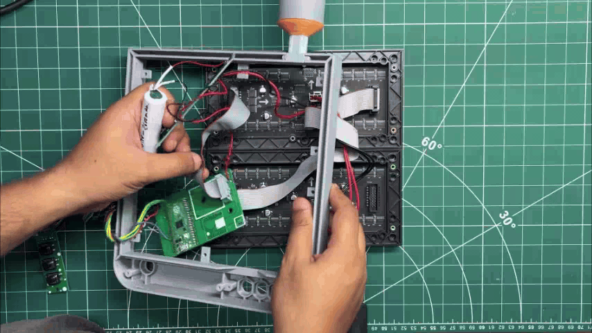
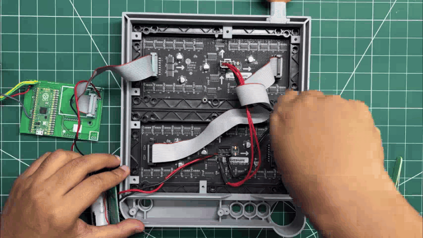
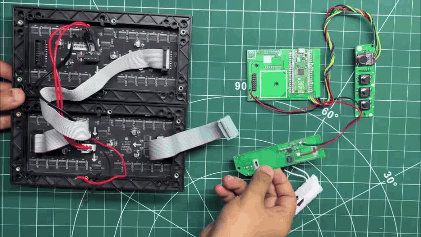
  1. Now comes the final assembly process, which begins by reconnecting the Pico Driver Board to the RGB matrices. We solder the VCC and GND wires of the matrices back to the 5V and GND terminals of the Pico Driver Board.
  2. Next, the 16-pin ribbon cable of the first matrix is reconnected to the HUB75 connector on the Pico Driver Board.
  3. Before proceeding further, we power up the setup to make sure everything is working correctly. Once we confirm that both matrix and the display are functioning properly, we begin assembling the enclosure.
  4. The Main Body is placed over the displays by aligning its mounting holes with the mounting points on the RGB matrices. We then use a total of ten M3 bolts to secure both matrices to the Main Body.
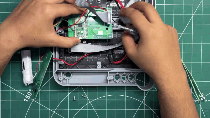
  5. Next, the Pico Driver Board is positioned between the two matrices by aligning its mounting holes with the mounting points on the matrices. Two M3 bolts are then used to secure the Pico Driver Board in place.
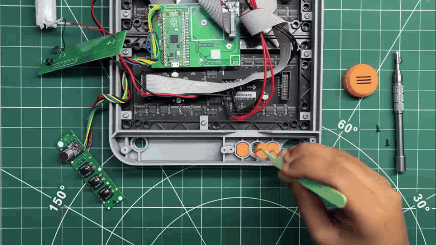
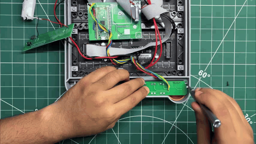
  6. The three orange Switch Actuators are positioned in their respective slots, followed by the orange Grille Part. The Switch Board is then placed over the three actuators and secured in place using M2 screws.
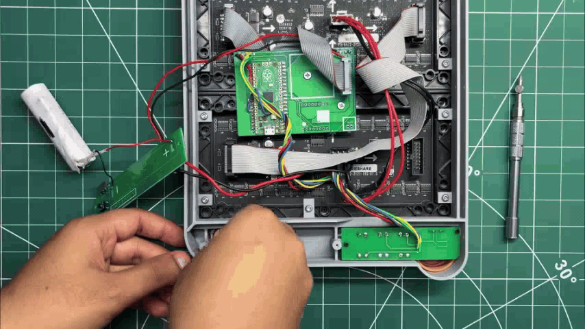
  7. Next, the orange actuator for the main power switch is positioned in its slot.
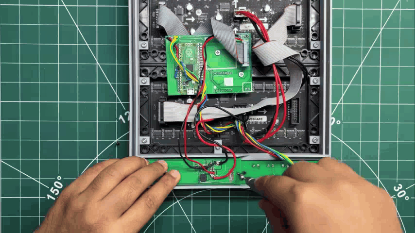
  8. The 3.7V lithium-ion cell is then placed inside the enclosure. The Power Board is positioned over the main switch actuator and lithium-ion cell and secured in place using M2 screws.
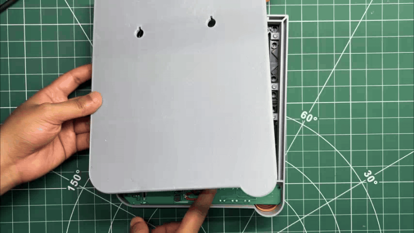
  9. Finally, the Back Lid is positioned on the rear side of the Main Body. M2 screws are inserted from the left and right sides and tightened to secure the Back Lid to the Main Body, completing the assembly process.

RESULT
PROJECT GESTALT: Meet the Matrix
PROJECT GESTALT: Here's What It Can Actually Do
58.gif
60.gif

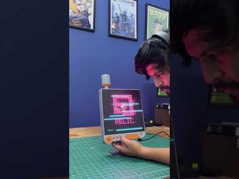
And here’s the end result of this project, PROJECT GESTALT, a fully functional RGB matrix display that combines animations, gaming-inspired visuals, and a sound-reactive WaveForm mode, all inside a custom enclosure inspired by the Pods from NieR: Automata.

To turn the device ON, we press the main power button, which powers up the system and initializes the display.

Three control buttons are provided: Previous, WaveForm Mode, and Next.

The Previous and Next buttons allow us to cycle through the different animations stored on the device. Pressing the Next button moves to the next animation, while the Previous button takes us back to the previous one.

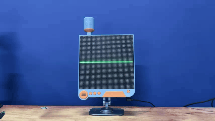
The dedicated WaveForm Mode button switches the device into its sound-reactive mode. In this mode, the microphone picks up the surrounding sound level, which is then visualized in real time as an animated wave on the RGB matrix. As the surrounding sound gets louder, the wave expands and reacts accordingly.

ANIMATIONS
46.gif
47.gif
48.gif
49.gif
50.gif
51.gif
52.gif
53.gif

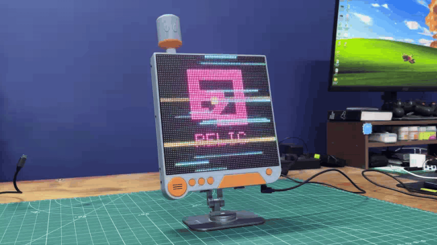
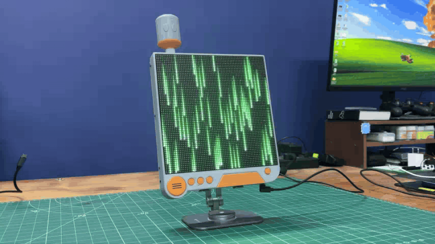
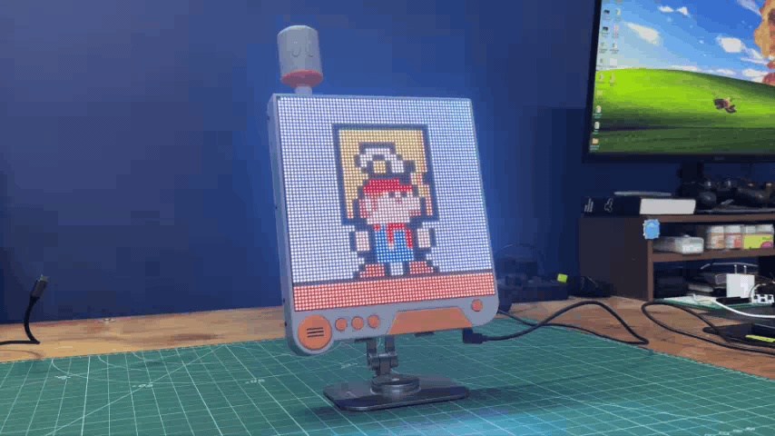
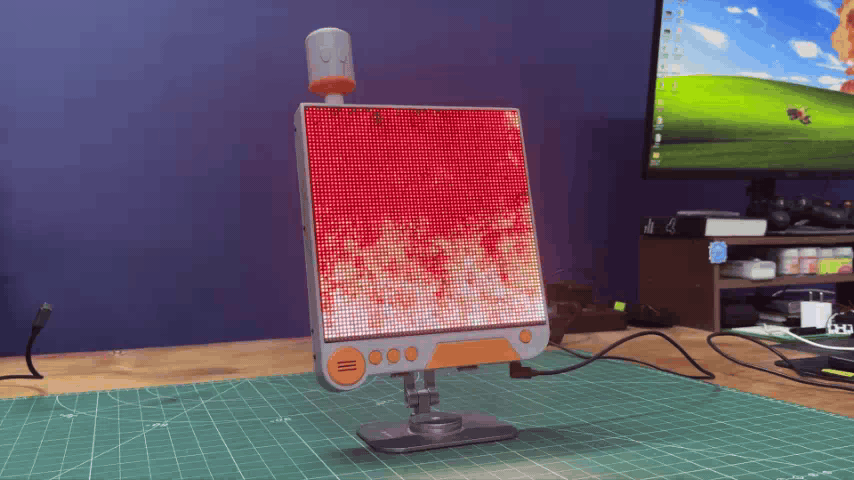
Project Gestalt currently features nine custom animations, each created using procedural graphics and lightweight code to run smoothly on the Raspberry Pi Pico.

  1. Cyber-Ghost- A colorful Pac-Man-inspired ghost with animated feet and continuously shifting RGB colors.
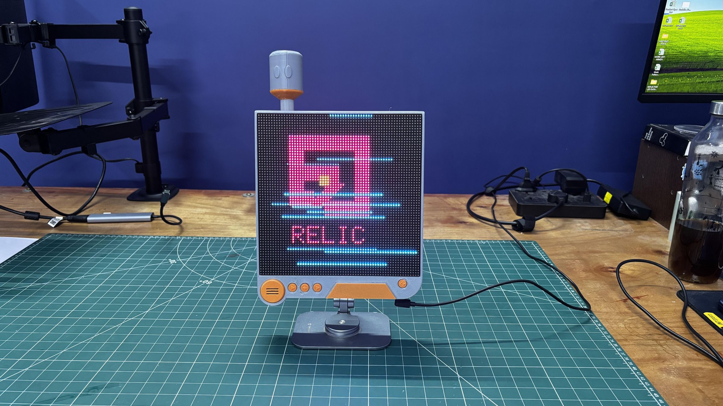
  2. Cyberpunk 2077 Relic- a Cyberpunk-inspired Relic logo featuring glitch effects, screen tearing, and randomized digital interference.
  3. Retro DOOM Fire- a classic pixelated fire effect inspired by old-school games and demoscenes, with flames dynamically rising across the display.
  4. XOR Cyber-Fractal- a constantly evolving geometric pattern generated using lightweight bitwise operations and procedural animation.
  5. Synthwave Outrun Grid- a retro 80s-inspired animated sunset and moving perspective grid that creates the illusion of traveling forward.
  6. Neon Qix Trails- inspired by the classic Mystify screensaver, featuring bouncing neon lines that leave colorful fading trails behind them.
  7. Pikachu- an animated 8-bit Pikachu with a bobbing head and moving mouth designed to mimic its iconic “Pika Pika!” expression. (This was my Fav one)
  8. It's a Me Mario- a miniature animated scene where Mario runs, jumps into a Question Block, and sends a gold coin flying out.
  9. Matrix Digital Rain- the iconic Matrix-inspired effect featuring streams of glowing green code continuously falling across the display.

WAVEFORM MODE
56.gif

Another feature I incorporated into Project Gestalt comes from one of my previous projects, WaveForm: The Background Sound Visualizer.

WaveForm is a sound-reactive visualizer that transforms surrounding sound into an animated wave displayed on a HUB75 RGB matrix. As the sound gets louder, the wave expands and reacts in real time.

Since Project Gestalt already uses a large RGB matrix, I ported my previously developed WaveForm code to this project as well. By pressing the dedicated WaveForm button, the device switches to an audio-reactive mode where the displayed wave responds to surrounding sounds in real time.

You can check out the complete WaveForm article from the link below.

https://www.instructables.com/WaveForm-the-Background-Sound-Visualizer/

Here's the code that I edited for the dual RGB Panel setup.

void drawWaveform() {
static float samples[OVERSAMP];
uint32_t sum = 0;

for (int i = 0; i < OVERSAMP; i++) {
int v = analogRead(MIC_PIN);
samples[i] = (float)v;
sum += v;
delayMicroseconds(100); // Slight speed up for better sampling
}

// DEBUG: Uncomment this line to check values in Serial Monitor (115200)
// Serial.println(sum / OVERSAMP);

float dc = (float)sum / (float)OVERSAMP;
float rmsSum = 0.0f;
for (int i = 0; i < OVERSAMP; i++) {
float centered = samples[i] - dc;
rmsSum += centered * centered;
}
float rms = sqrtf(rmsSum / (float)OVERSAMP);

if (!noiseInit) { noiseFloor = rms; noiseInit = true; }
noiseFloor = (0.95f * noiseFloor) + (0.05f * rms);

float rmsEffective = rms - (noiseFloor * 1.2f); // Slightly higher gate
if (rmsEffective < 0.0f) rmsEffective = 0.0f;

rmsPeak = (0.99f * rmsPeak) + (0.01f * rmsEffective);
float loud = (rmsPeak > 5.0f) ? (rmsEffective / rmsPeak) : 0.0f;
loudSmooth = (0.7f * loudSmooth) + (0.3f * loud);

// Build points
for (int i = 0; i < NUM_POINTS; i++) {
float s = samples[i * (OVERSAMP / NUM_POINTS)];
float amp = loudSmooth * (H / 2.0f);
float y = (H / 2.0f) - ((s - dc) * amp / 500.0f);
if (y < 0) y = 0; if (y >= H) y = H - 1;
waveY[i] = y;
}

uint16_t waveColor = rgb(0, 255, 0); // Solid green wave
for (int i = 1; i < NUM_POINTS; i++) {
matrix.drawLine((i - 1) * X_STEP, (int)waveY[i - 1], i * X_STEP, (int)waveY[i], waveColor);
}
}

CONCLUSION

IMG_E0206.JPG
60.gif
IMG_E0179.JPG
IMG_E0180.JPG

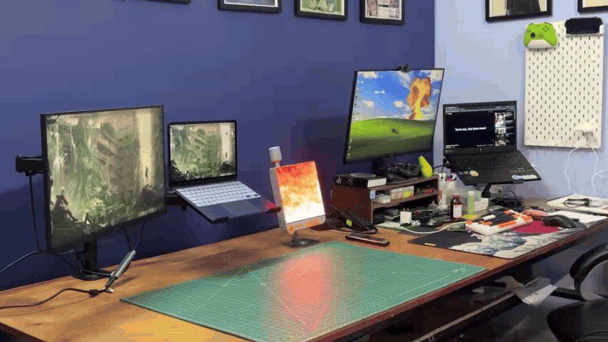
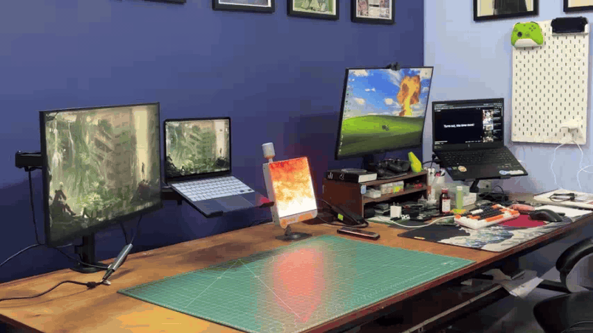
This project has been a success, and one of my favorite things about Project Gestalt is its versatility. It can either be mounted on a wall or placed on a desk using a stand, making it a great interactive and aesthetic addition to my workspace.

The device currently features nine custom animations along with the sound-reactive WaveForm mode. More animations can easily be added in the future, keeping the display fresh and interesting over time.

There are also several upgrades I’m planning for the next version of this project. One major improvement would be replacing the Raspberry Pi Pico with a Pico W to add Wi-Fi functionality, which could allow images and other content to be sent wirelessly to the matrix. I would also like to add a DFPlayer Mini module to bring audio playback to the project.

These upgrades will hopefully make the next version of Project Gestalt even more interactive and capable. For now, I’m quite happy with how this version turned out, and I hope you liked the project as well.

For now, Project Gestalt is complete, and all the details you need to build your own version are available in this article, including the code, schematic, enclosure files, and complete build instructions.

Special thanks if you made it this far, and I hope you enjoyed reading about this project as much as I enjoyed building it.

I’ll be back with another project very soon. Until then, stay tuned, and happy making!