Project P.U.S.H.: Pneumatic Urban Speed Harness – Compact Coaster Engineering
by disha_pure123 in Outside > Backyard
142 Views, 3 Favorites, 0 Comments
Project P.U.S.H.: Pneumatic Urban Speed Harness – Compact Coaster Engineering
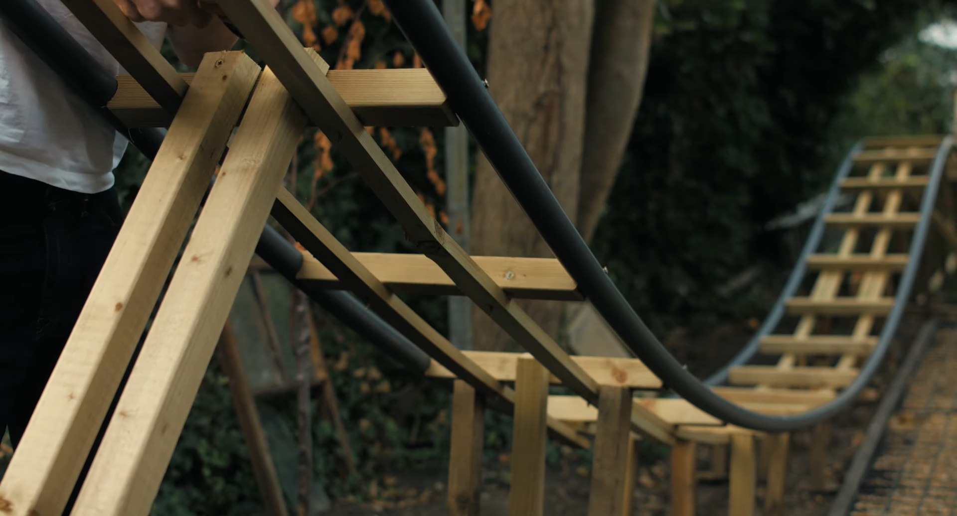
Building a backyard roller coaster is one of the ultimate hands-on engineering projects. While traditional roller coasters rely on a tall hill and chain lift to build potential energy, tight backyard spaces require a different approach. This project uses a compressed-air pneumatic launch system—the same concept behind commercial "accelerator" coasters—to propel a custom cart along a track instantly from ground level. By combining high-pressure PVC pipe, custom wooden framing, and a 3-wheel capture system on the car, you can safely build a functional, exhilarating ride right in your yard.
Supplies
Supplies And Materials List
1. Pneumatic Launch System
- Cylinder Pipe: 1x 2.5-meter (8-foot) length of 90 mm (3.5-inch) high-pressure rated PVC pipe (Class 12 or PN16).
- End Caps: 2x 90 mm pressure-rated PVC caps (one solid for the rear, one drilled center hole for the front guide).
- Piston Head: 3/4-inch exterior-grade plywood sheet (to cut circular discs) + thick rubber sheets or O-rings for airtight seals.
- Push Rod: 1x 1/2-inch threaded steel rod (3 to 4 feet long) with matching nuts, locking washers, and heavy-duty steel washers.
- Air Storage: 1x 5 to 10-gallon steel air compressor tank (rated for at least 150 PSI).
- Valves & Fittings: 1x 1-inch or 1.5-inch high-flow quick-exhaust valve (or fast-acting pneumatic solenoid), inline pressure regulator with analog gauge, and high-pressure air hoses with quick-connect fittings.
- Lubrication: Silicone grease (for piston seals).
2. Roller Coaster Track & Framing
- Main Rails: 1.5-inch or 2-inch Schedule 80 PVC pipes (length depends on your total track design).
- Support Framing: 2x4 and 2x6 construction-grade pressure-treated lumber (for A-frame trestles and horizontal stringer beams).
- Track Fasteners: 3-inch exterior deck screws and countersunk wood screws (to attach PVC rails to stringers without snagging wheels).
- Concrete / Ground Anchors: Rebar stakes or concrete footers to anchor track trestles firmly to the ground.
3. Coaster Cart (Vehicle)
- Chassis: 3/4-inch exterior plywood and 2x4 lumber.
- Wheels: 12 to 18 heavy-duty polyurethane wheels or inline skate wheel assemblies (6 wheels per side: 2 runner wheels, 2 side-friction wheels, 2 up-stop wheels).
- Hardware: 1/2-inch steel bolts, locknuts, washers, and steel mounting brackets for wheel trucks.
- Catch Plate: 1/4-inch thick steel plate or reinforced hardwood block mounted on the cart rear.
4. Safety & Braking
- Piston Stop: Heavy rubber bumper block or spring dampener inside the cylinder end.
- Brakes: Heavy-duty rubber pads and lever assembly for manual squeeze brakes, or high-friction rubber mats for the deceleration zone.
- Tools Needed: Drill and bit set, hole saw kit, miter saw or circular saw, pipe wrench, adjustable wrenches, pipe primer and heavy-duty PVC cement, tape measure, level, and safety goggles.
Pre-Build Engineering & Physics Calculations
Before buying materials, calculate your target velocity and safety tolerances:
- Target Force: Calculate the surface area of your piston head (Area = pi * r^2). For a 90 mm (3.54-inch) ID pipe, the surface area is roughly 9.8 to 12 sq inches.
- Pressure Math: At 100 PSI (6.9 bar), 12 sq in * 100 PSI = 1,200 lbs (5.33 kN) of linear force.
- Launch Distance: A 2.5-meter (8.2-ft) cylinder stroke accelerates a 30-lb car plus rider to speed instantly.
Build the Pneumatic Launch Cylinder
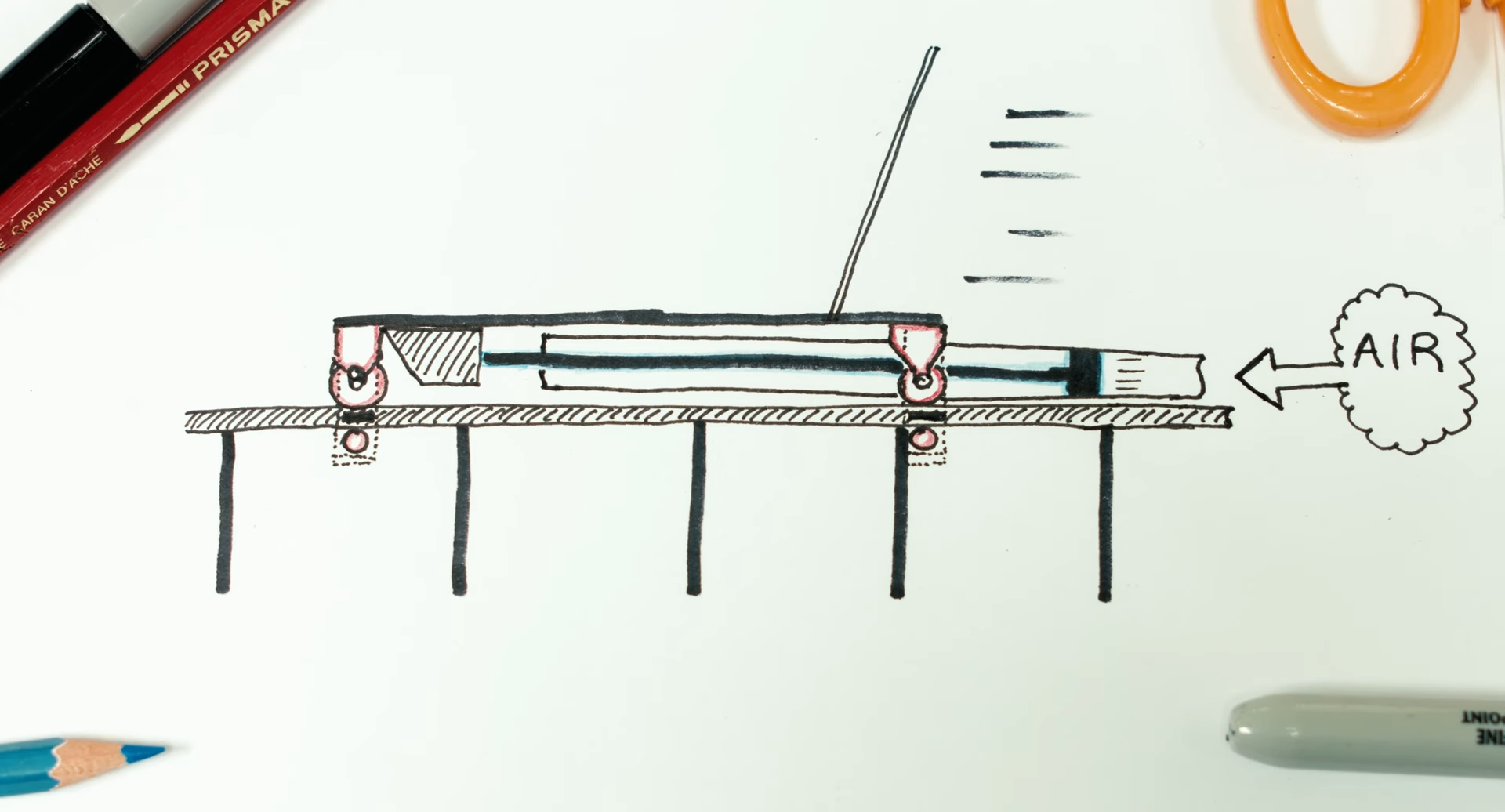
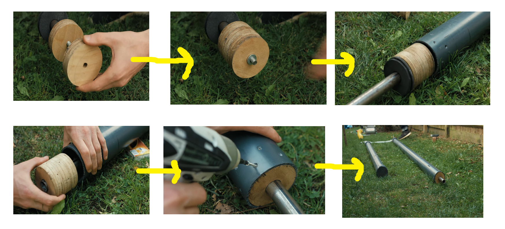
The cylinder acts as the "engine" beneath the track.
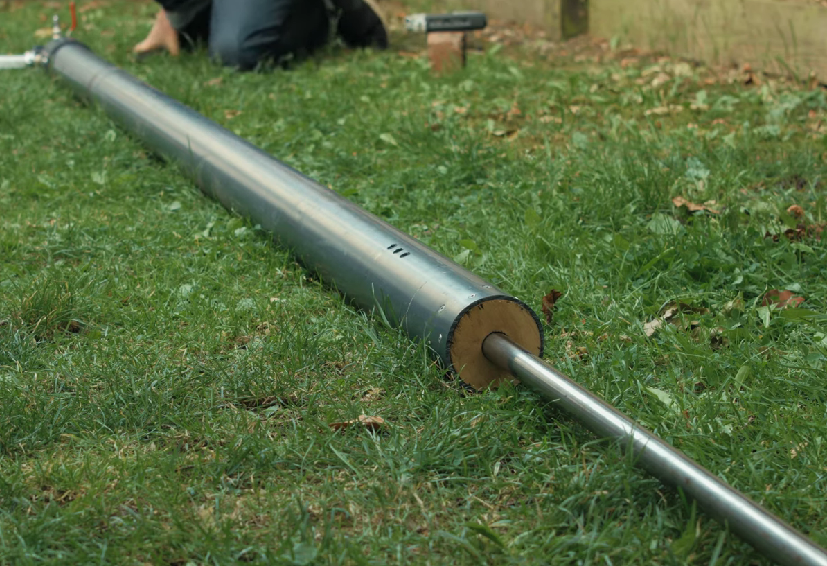
- Cylinder Barrel: Cut a length of 90 mm Class 12 or PN16 high-pressure rated PVC pipe to 2.5 meters. Glue a solid PVC end cap to the rear.
- Piston Head:
- Cut 3 to 4 circular discs of 3/4-inch high-density plywood using a hole saw matching the exact inner diameter of the PVC pipe.
- Sandwich rubber gasket discs or O-rings between the wooden discs to create an airtight seal against the cylinder walls.
- Coat the perimeter with silicone grease.
- Pusher Rod: Thread a 1/2-inch steel threaded rod through the center of the wooden disc sandwich. Secure both sides with heavy washers and nylon locking nuts.
- Front Cap: Cap the front of the pipe with a drilled end cap to act as a linear guide bearing for the steel rod.
Air System Plumbing & Controls
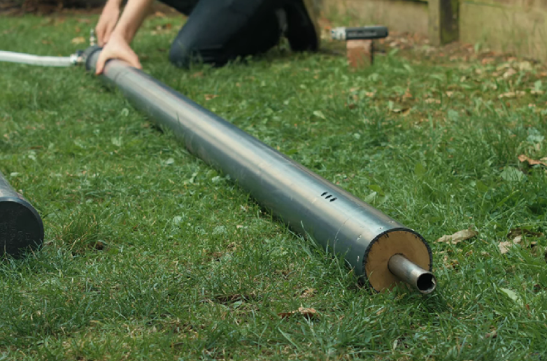
Air Storage Tank: Mount a steel pressure tank (minimum 5 to 10 gallons, rated for 150+ PSI) below the launch track.
High-Flow Valve: Connect the tank to the rear cap of the 90 mm cylinder using a 1-inch or 1.5-inch rapid-discharge valve (such as a quick-exhaust valve or high-flow pneumatic solenoid).
Control Line: Install an inline pressure regulator and analog pressure gauge to tune launch speeds before each test run.
Downloads
Construct the Wooden Chassis & Wheel Assembly
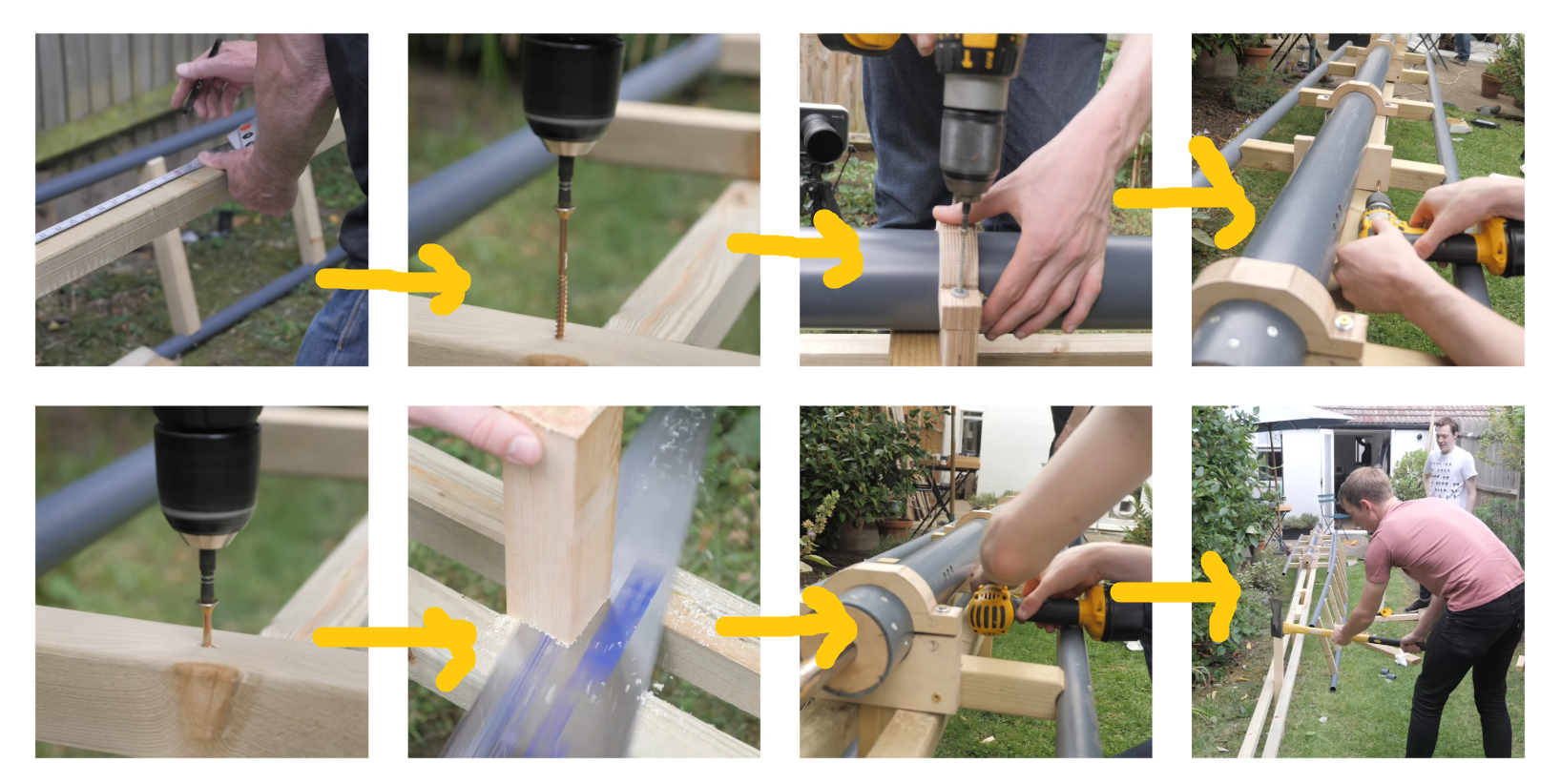
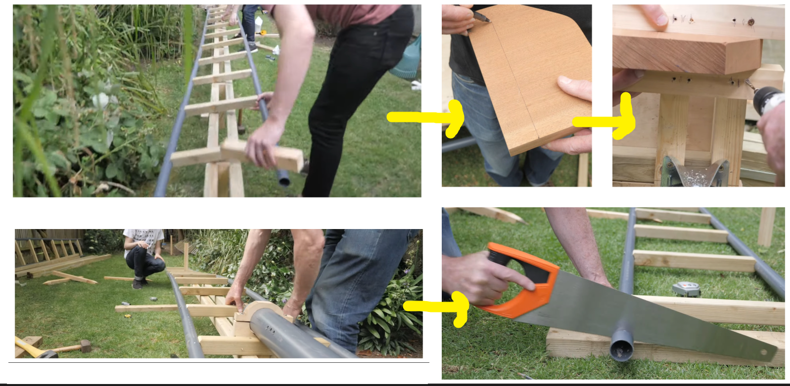
Detailed Guide
The coaster car (cart) is the most critical mechanical component of the entire project. Because the launch system subjects the vehicle to sudden, high-force acceleration, the chassis must be rigid and structural. Furthermore, to guarantee the car cannot fly off the track during airtime or lateral turns, it uses a 3-wheel capture assembly on each rail (6 wheels per side, 12 wheels total).
Step 1: Chassis Frame Construction
The chassis must withstand both the forward impact of the launch rod and the structural twisting (torsion) of the track without flexing.
- Base Plate Cutting:
- Cut a piece of 3/4-inch exterior-grade (BCX or Marine) plywood to 24 inches wide by 36 inches long. This serves as the main floor pan.
- Perimeter Reinforcement Frame:
- Cut two 36-inch pieces and three 21-inch pieces of 2x4 pressure-treated lumber.
- Frame the underside of the plywood base plate by screwing the 2x4s on-edge along the perimeter and placing one cross-brace directly through the center.
- Secure the plywood to the frame using 2-inch construction screws, spaced every 4 inches along the edges. Apply waterproof wood glue between the plywood and 2x4s before screwing them together.
- Piston Impact / Catch Block:
- Cut a block of solid hardwood (such as oak or maple) measuring 4x4x8 inches, or laminate multiple layers of 3/4-inch plywood together.
- Mount this block squarely in the rear-center of the underside chassis, aligned precisely with the height of the emerging piston push-rod.
- Face the striking side of the block with a 1/4-inch thick steel plate fastened with four countersunk lag bolts to prevent the steel push-rod from splitting the wood over time.
- Seat & Rider Restraints:
- Build a low-back bucket seat out of 3/4-inch plywood or securely bolt a plastic go-kart/lawnmower bucket seat directly through the floor pan using 3/8-inch Grade 8 bolts with wide fender washers underneath.
- Anchor a heavy-duty ratchet strap or lap belt through the chassis frame using forged steel eyebolts.
Step 2: Wheel Truck Geometry & Principle
To ensure total track retention, each rail requires three distinct wheel groups working together in a rigid housing:
- Runner Wheels (Load Bearing): Ride directly on top of the PVC rail to carry the combined weight of the car and rider.
- Side-Friction Wheels (Lateral Guide): Ride on the inner (or outer) vertical curve of the pipe rail to keep the car centered and prevent derailment on curves.
- Up-Stop Wheels (Anti-Lift): Ride along the underside curve of the pipe rail to lock the cart to the track during negative-G airtime or rapid acceleration.
Step 3: Fabricating the 3-Wheel Capture Housing
You will build two identical wheel truck housings (one for the left rail, one for the right rail). Each housing holds 6 wheels.
Materials Needed per Housing:
- 2x Heavy-duty steel L-brackets (1/4-inch thick steel angle iron or 3/16-inch thick custom steel plates).
- 6x High-rebound polyurethane inline skate wheels (76mm to 80mm diameter with ABEC-7 or ABEC-9 bearings) or heavy-duty industrial caster wheels.
- 6x Grade 8 steel bolts (5/16-inch or 3/8-inch diameter, 3.5 inches long) with matching nylon-insert locknuts and washers.
- Steel or aluminum spacers to position wheels away from the frame walls.
Assembly Steps for One Housing:
- Mounting Plate Layout:
- Take a 1/4-inch thick steel angle bracket or custom plate (approx. 18 inches long) that bolts directly to the side of your 2x4 chassis frame.
- Positioning the Runner Wheels (Top):
- Drill two horizontal axle holes through the top section of the plate spaced 12 inches apart.
- Pass 3/8-inch bolts through the plate, add steel spacers, slide on the 80mm polyurethane runner wheels, and secure with locknuts. These two wheels bear the main weight.
- Positioning the Side-Friction Wheels (Middle):
- Drill two vertical axle holes on the inner face of the housing, set inward toward the center line of the rail.
- Mount two wheels vertically so their tread surface rolls smoothly along the side curve of the 2-inch PVC rail with roughly 1/16-inch of clearance to prevent binding.
- Positioning the Up-Stop Wheels (Bottom):
- Drill two horizontal axle holes at the lower lip of the housing bracket, positioned directly under the rail pipe.
- The vertical distance between the bottom of the top runner wheel and the top of the lower up-stop wheel must equal the exact outer diameter of your rail pipe (e.g., 2.375 inches for a 2-inch Schedule 80 pipe) plus 1/16-inch running clearance.
- Insert the bolts and wheels. When installed, the pipe rail will be "sandwiched" tightly between the top runner wheel and the bottom up-stop wheel.
Step 4: Mounting and Aligning Wheels on the Chassis
- Alignment:
- Bolt the left and right wheel assemblies to the chassis base frame using 3/8-inch Grade 8 carriage bolts.
- Measure the exact center-to-center distance between the left and right wheel channels. This must match your track rail gauge down to 1/16-inch.
- Tolerance Testing:
- Slide the completed chassis onto a 4-foot sample section of your dual PVC track.
- The car should glide smoothly along the pipe without noticeable side-to-side wobble.
- Attempt to lift the car vertically off the track: the lower up-stop wheels must make immediate contact with the bottom of the pipe, preventing the cart from lifting more than 1/8-inch.
- Final Fastener Safety:
- Apply medium-strength threadlocker (Blue Loctite) to every axle bolt and chassis fastener to ensure vibration during operation cannot back nuts off the bolts.
Build Track Structures & Lay PVC Rails
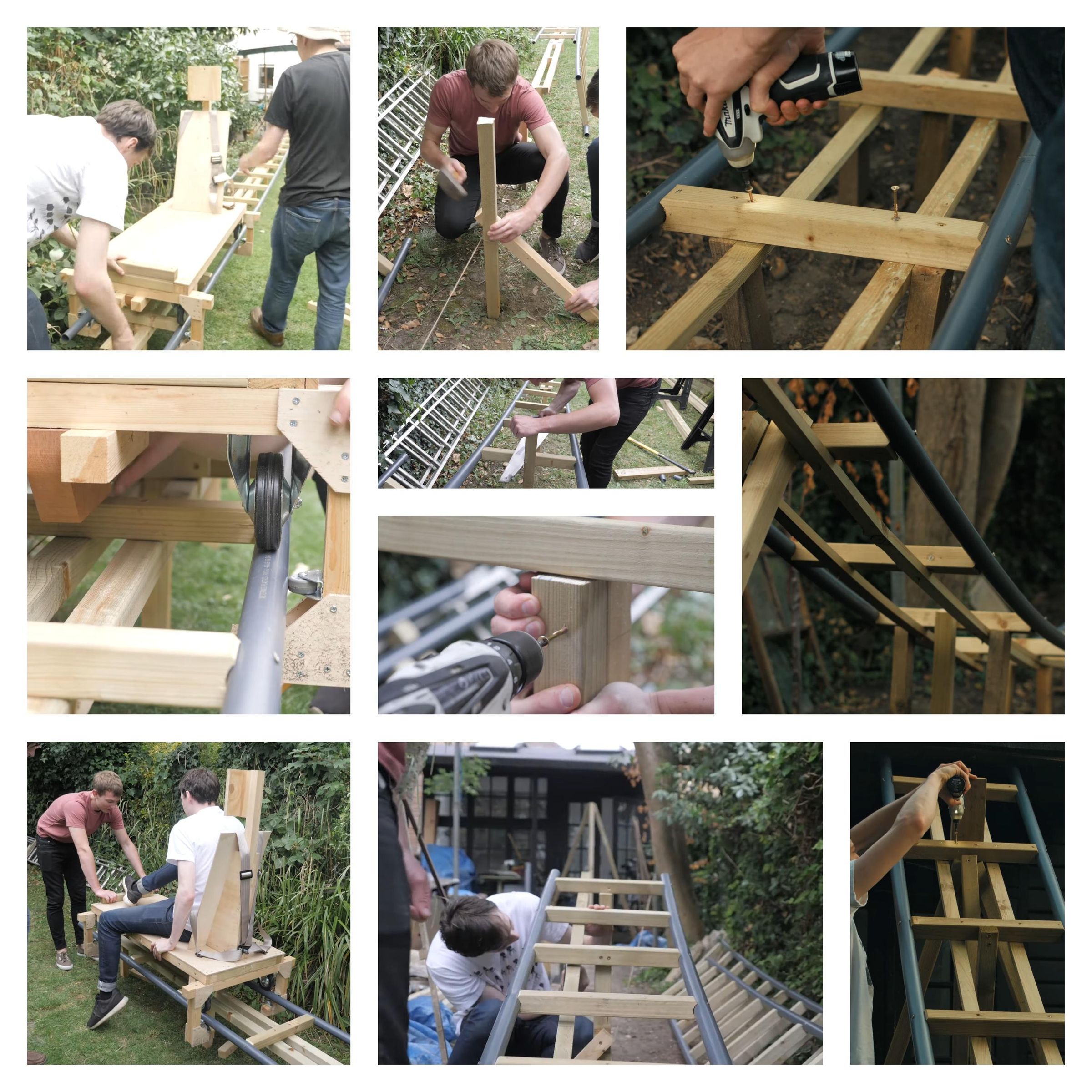
Detailed Guide
The track structure consists of two components: the wooden support framework (footings, trestles, and longitudinal stringer beams) and the PVC rail pipes (the running surface). Because the launch coaster generates high linear forces and dynamic weight shifts, the track must remain completely rigid and maintain an exact gauge (distance between rails) along its entire length.
Step 1: Site Survey & Layout Plan
- Grade Assessment:
- Choose a flat, level strip of yard for the launch track section.
- Run a mason line (string line) stretched tight between stakes at both ends of your proposed track route. Attach a line level to ensure the launch track is 100% horizontal.
- Track Gauge Selection:
- Select a fixed inner gauge distance for your rails (typically 18 inches to 24 inches center-to-center).
- Stick to this exact dimension across the entire build—even a 1/4-inch deviation will cause the cart's wheels to bind or derail.
Step 2: Constructing Wooden Support Trestles (A-Frames)
The A-frame trestles absorb all vertical weight loads and lateral forces from the moving cart.
- Trestle Spacing:
- Build and position one A-frame trestle every 24 inches to 36 inches along the track route. Spacing trestles further than 36 inches allows PVC rails to flex downward under load.
- Cutting A-Frame Components (Per Trestle):
- Bottom Base Plate: 1x 2x4 lumber cut to 36 inches long (sits flat on the ground/footers).
- Top Cross Tie: 1x 2x6 lumber cut to match your track width plus 6 inches (e.g., 28 inches long for a 22-inch rail gauge).
- Angled Legs: 2x 2x4 lumber cut at a 15-degree miter angle on both ends (length depends on your desired track height, usually 18 to 24 inches tall).
- Trestle Assembly:
- Lay the base plate, two angled legs, and top 2x6 cross tie flat on a work table.
- Secure all joints using 3-inch exterior deck screws and 1/2-inch exterior plywood gusset plates glued and screwed across each wood intersection.
- Ground Anchoring:
- Set each trestle base plate onto concrete deck blocks or level paver stones to prevent wood rot from direct ground contact.
- Drive two 24-inch lengths of 1/2-inch steel rebar through pre-drilled holes in the bottom base plate deep into the soil at opposite angles to lock the trestle in place.
Step 3: Installing Longitudinal Stringer Beams
Stringers run parallel to the track, spanning across the tops of all A-frame trestles. They provide the flat structural bed that the PVC pipe rails screw onto.
- Beams Mounting:
- Position continuous lengths of 2x6 (or 2x4) pressure-treated lumber flat or on-edge along the top left and top right edges of the trestles.
- Butt-joint the ends of stringer boards directly over the center of a trestle top cross-tie. Overlap joints with 2-foot sister boards screwed alongside for added stiffness.
- Leveling & Alignment:
- Sight down the length of the stringer beams using a 4-foot level. Shim underneath the stringers where necessary so the entire run is straight and flat.
Step 4: Preparing & Bending PVC Rail Pipes
- Pipe Material:
- Use 1.5-inch or 2-inch Schedule 80 PVC pipe (gray electrical conduit or thick-walled pressure pipe). Schedule 80 has thicker walls than standard Schedule 40 white PVC, which prevents screws from pulling through under load.
- Joining Rail Sections:
- Clean pipe ends with PVC primer and join sections using Schedule 80 deep-socket couplings and heavy-duty PVC cement.
- Stagger the pipe joints between the left and right rails (e.g., if the left rail has a joint at 10 feet, place the right rail joint at 15 feet) to prevent structural weak points in the track.
Step 5: Mounting PVC Rails to Stringer Beams
This step requires precision to ensure the track remains parallel and the running surface stays smooth.
- Fabricate a Track Gauge Jig:
- Cut a piece of 2x4 to the exact target spacing required between the inner walls of your two PVC pipes. Use this wooden spacer block continuously as you attach the rails.
- Drilling & Countersinking Rail Holes:
- Drill vertical pilot holes straight through the top and bottom walls of the PVC pipe every 12 inches.
- Use a countersink drill bit on the top hole only of the PVC pipe. The screw head must sit completely flush or slightly below the outer pipe surface so the cart's runner wheels do not bump against screw heads.
- Securing the First Rail:
- Align the first PVC pipe along the outer edge of the left stringer beam.
- Drive 3.5-inch heavy-duty construction screws down through the top hole of the pipe, through the bottom hole, and firmly into the wooden stringer below.
- Securing the Second Rail (Using the Gauge Jig):
- Position the second PVC pipe on the right stringer beam.
- Insert your wooden track gauge jig between the two pipes at the first screw location to lock in the exact spacing.
- Clamp the pipe down, drill, and screw it in place.
- Move the gauge jig down to the next screw location (12 inches ahead) and repeat the process for the entire length of the track.
Step 6: Track Inspection & Finishing
- Smoothness Check:
- Run your hand along the top surface of both PVC rails to feel for raised screw heads, rough glue joints, or plastic burrs.
- Sand down any raised pipe joints or rough spots using 120-grit sandpaper until completely smooth.
- Manual Test Run:
- Take the completed car chassis (without a rider) and push it by hand along the entire track section.
- Ensure the wheels roll smoothly with zero binding, excessive side-to-side play, or vertical lifting.
Safety, Brakes & Calibration Protocol
Summary Checklist: Calibration & Safety Sequence
- Safety Controls:
- Install a 120 PSI ASME safety relief valve on the air tank.
- Add a manual ball valve on the main line to isolate air during loading.
- Place an internal rubber bumper and steel cross-bolt inside the front cylinder cap to catch the piston rod.
- Braking System:
- Build squeeze brakes (padded 2x6 boards with rubber lining that clamp the chassis sides) or use friction pads on the final 10–15 feet of track runout.
- 3-Stage Testing:
- Stage 1 (Dry Test): Fire the cylinder unloaded at 30, 40, 60, and 80 PSI to check seal leaks and piston travel.
- Stage 2 (Ballast Test): Load the car with 150 lbs of sandbags. Step up pressure in 10 PSI increments. Run 10 consecutive flawless tests at max operating pressure before human trials.
- Stage 3 (Manned Run): Keep air isolated during loading, secure safety restraints, give a clear verbal countdown, and inspect hardware after every run.