Project Senegal: Novel Approach to Housing
by samfrk10 in Design > Architecture
1701 Views, 9 Favorites, 0 Comments
Project Senegal: Novel Approach to Housing


Hello! My name is Sam, and I am a rising sophomore at Ballantyne Ridge High School in Charlotte, North Carolina. I’m passionate about design, 3D printing, and competing in challenges that push me to grow my skills. I’m proud to be one of the lead designers on my high school robotics team, Circuit Breakers, which competes in FTC. I love creating innovative parts that combine both style and function. I first heard about this competition through a peer who encouraged me to step beyond my usual boundaries and learn new software tools. During a mission trip to Senegal, I met boys who were homeless—kids who had been rejected by their families and had nowhere to turn. As we traveled the highways, I saw countless houses made of bare concrete with no roofs. Although some individuals were trying to help, they simply couldn’t shelter everyone in need. Returning to the States, I felt compelled to act. For this competition, I began designing and building a house that not only provides shelter but also restores hope to these boys and their communities. With great pride, I present to you Project Senegal.
Supplies
Software:
Autodesk Fusion for 3D printing (Student license available)

Bambu Lab slicer or any other slicer, depending on the 3d printer for 3D printing (Free to download)

Materials:
A4 paper
Plastic Wrap
Super Glue
Spray paint(black)
Tape
Tools:
3D printer (Preferably 15.3 x 15.3 x 18 inches)
Scissors
Toothpick
Table of Contents:
Research:
Step 1: Inspiration
Step 2: Problems
Step 3: Income
Step 4: Solutions
Step 5: Government Guidelines & Restrictions
Step 6: Beer Sheba
CAD:
Step 7: Fusion/Reference Sheet
Step 8: Initial Designs for “Sunmill”
Step 9: Sunmill
Step 10: The Design
Step 11: Soundation
Step 12: First Module
Step 13: Second Module
Step 14: Third Module
Step 15: Entrance
Step 16: Rendering
Implementation:
Step 17: Materials
Step 18: Budget
Step 19: 3D Soil printing
Manufacturing:
Step 20: 3D Printing
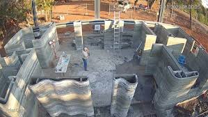
Step 21: Onsite Assembly
Testing the Model:
Step 22: Location
Step 23: Testing Location
Step 24: Testing the model
Closing:
Step 25: Reflection
Step 26: Acknowledgments
Inspiration
Two experiences shaped who I am this past year, both involving the issues I saw around me and in the wider world. During the summer, my friends went on a mission trip to Dakar, Senegal. On that trip, I was deeply impacted by witnessing the struggles of families facing homelessness. There were boys on the streets who were around our age but lacked the opportunities to pursue any sense of financial security. As we traveled along the highways, we saw unfinished concrete houses with no roofs, fully exposed to the rain and intense heat of Senegal. Steel pillars protruded from the tops of these structures, and the walls offered little protection, making them hardly feel like homes at all.
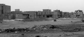
These pictures show how bare and unsettling these houses are, making them almost look like prisons.
Source: Opendemocracy
This is what many houses in Senegal look like because families often lack the financial resources to continue building. They are forced to stop construction and live in these incomplete concrete shells as best they can. We also saw children begging for food because their families had turned them away. The missionaries we accompanied had set up small camps to provide temporary shelter for some of these boys, but the camps could only accommodate a small number. At night, most of the boys still had to sleep on the streets. These children mostly boys were so grateful and content with everything that they had even though they had little to nothing, they wer always filled with joy and loved ot play soccer. So while we were there we always wanted to do something for the boys but it never seemed like it was enough so this is something that i am trying ot do for them and those struggling with chronic homelessness everywhere..
Coming back to Charlotte, I don't have to look far to see this problem. Every Saturday, my family serves at a local Pantry where our church provides breakfast for some homeless families. Through this, I saw how easy it is to fall into homelessness and how easily my family could have fallen into this hole, which seems never-ending. Every time I went there, I always saw different experiences of the homeless. I was grateful every time, but I wanted to do something for them.
These two experiences may seem far from each other, but they're very connected. This affects people anywhere, in Senegal or Charlotte or anywhere around the globe; the issue has been the same underlying cause: humans are lacking safe, affordable, dignified homes. This experience brought me to do something for them, to create a simple, impactful idea, and a modular home that emphasizes Modernness. I can handle the climate and weather in different places, so it can be easily moved and replicated.
This house should not be discriminatory of area, whether in the sand plain of Senegal, or under the clay-filled soil of Charlotte. This house should unify every single area with a living space for people to thrive, maybe joyfully. This project isn't just about reading a house or some people who live in it. Creating a magnification glass for people to be seen as if the boys were trash, and families were treated very poorly. It's not just about architecture, but it's about providing hope.
Problems
Affordability and Economic Barriers
One of the largest issues in Senegal and cities like Charlotte is that building is extremely costly when compared to wages. For most families, even a small home is financially out of reach in terms of price. Traditional building usually involves massive initial payments and long-term obligations, which low-income individuals simply can't afford, with the consequence of half-completed houses or prolonged homelessness. As shown in the graph below, the growth in average house values in the United States has far surpassed the increase in individual annual incomes.

Source: CNBC
This graph compares the incomes of individuals in the United States to the corresponding housing costs, highlighting a very noticeable difference between how earnings have grown and how much housing expenses have increased.
Material Scarcity and Environmental Suitability
In other regions, such as Senegal, building materials are unavailable, expensive, or poorly adapted to the local environment. Unadapted building materials fall apart quickly when used to build homes. Water penetration and foundation collapse are common in highly clay environments. Long-term sustainability is effectively impossible without modular, adaptable materials. As seen in the article below most houses in Senegal and other third world countries are organic.
Incomplete or abandoned construction projects
The majority of families begin building houses with minimal savings, only to leave them halfway when funds run out. This leads to extensive structural weakness—ceilings without cover, walls open, and no reinforcement. Such homes give little protection from the elements and security for the residents.
Design Mismatch and Cultural Disconnect
The majority of budget-friendly housing schemes fail because they are imports brought from somewhere else, ignoring local needs, climates, and lifestyles. Homes that disavow cultural practices—like cooking in common, living in multiple generations, or airflow preference—get vacant or abandoned. A successful housing solution must be sensitive to the environment it is constructed for.
Scalability and Replication Challenges
Even if a housing solution works in one location, it typically cannot be reproduced elsewhere because of complex logistics, dependency on local resources, or a breakdown of modularity in design. Without the ability to easily reproduce across geography and economic realities, even great ideas never reach the people who need them most.
Income
The gap between affordable housing and income has been continuing to grow, as indicated by the graph. The major goal of this project is to bring down the cost of housing without sacrificing comfort. The average pay for homeless individuals is less than $54,000 per year, making it even more difficult to create affordable housing because no more than 30% of one’s income should go to housing. So, creating housing with that value is around $16,200 per year or $1,350 per month, which is about $300 below the average amount spent per month for an apartment in Charlotte. Though this may seem possible, $1,350 per month should be the absolute maximum to reach a wider population of those affected by homelessness.
As homelessness continues to grow, the issue of the income of people is affected by homelessness and becomes more influential in the area of affordable housing.
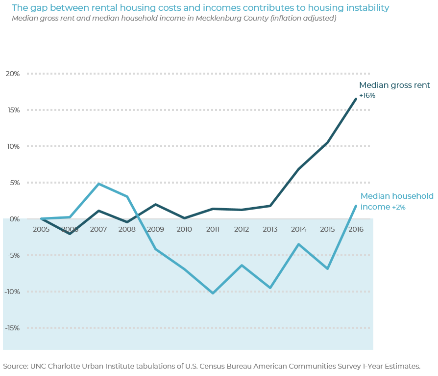
Comparison of Household Incomes and Rental Costs in Mecklenburg County
Source: Charlotte Mecklenburg Housing and Homelessness Dashboard
The gap between affordable housing and income has been continuing to grow, as indicated by the graph. The major goal of this project is to bring down the cost of housing without sacrificing comfort. The average pay for homeless individuals is less than $54,000 per year, making it even more difficult to create affordable housing because no more than 30% of one’s income should go to housing. So, creating apartments with that rental value is around $16,200 per year or $1,350 per month, which is about $300 below the average amount spent per month for an apartment in Charlotte. Though this may seem possible, $1,350 per month should be the absolute maximum to reach a wider population of those affected by homelessness. For housing through a 30-year mortgage, the total cost of the house should be at a maximum $486,000 for a family with 10 kids.
Solutions
To address the issues presentedcost and partial construction to incompatibility with local culture, and no skilled labor the following three strategies of design are the basis of an affordable, adaptive, and people-centered modular housing system:
1. Incremental Modular Design
Houses are constructed as a starter living unit that can be added to at a later date, so that families can begin small and grow as finances become available. This lowers the cost of entry, eliminates half-finished houses, and frees up design. The modular process provides for building in series without losing building integrity. For example as
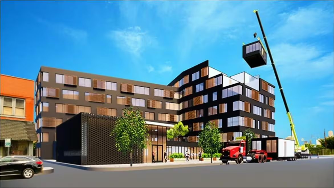
Construction of Prefabricated Units: Creating an Integrated Apartment Building
Source: Autodesk
2. Climate-Responsive Local Materials
Using local materials such as compressed earth blocks or clay bricks, the houses may be merged into the landscape, cool in the summer, and be cost-effective. The design is compatible with different soils (sand, clay) and has overhanging shaded areas and raised foundations for comfort and longevity.
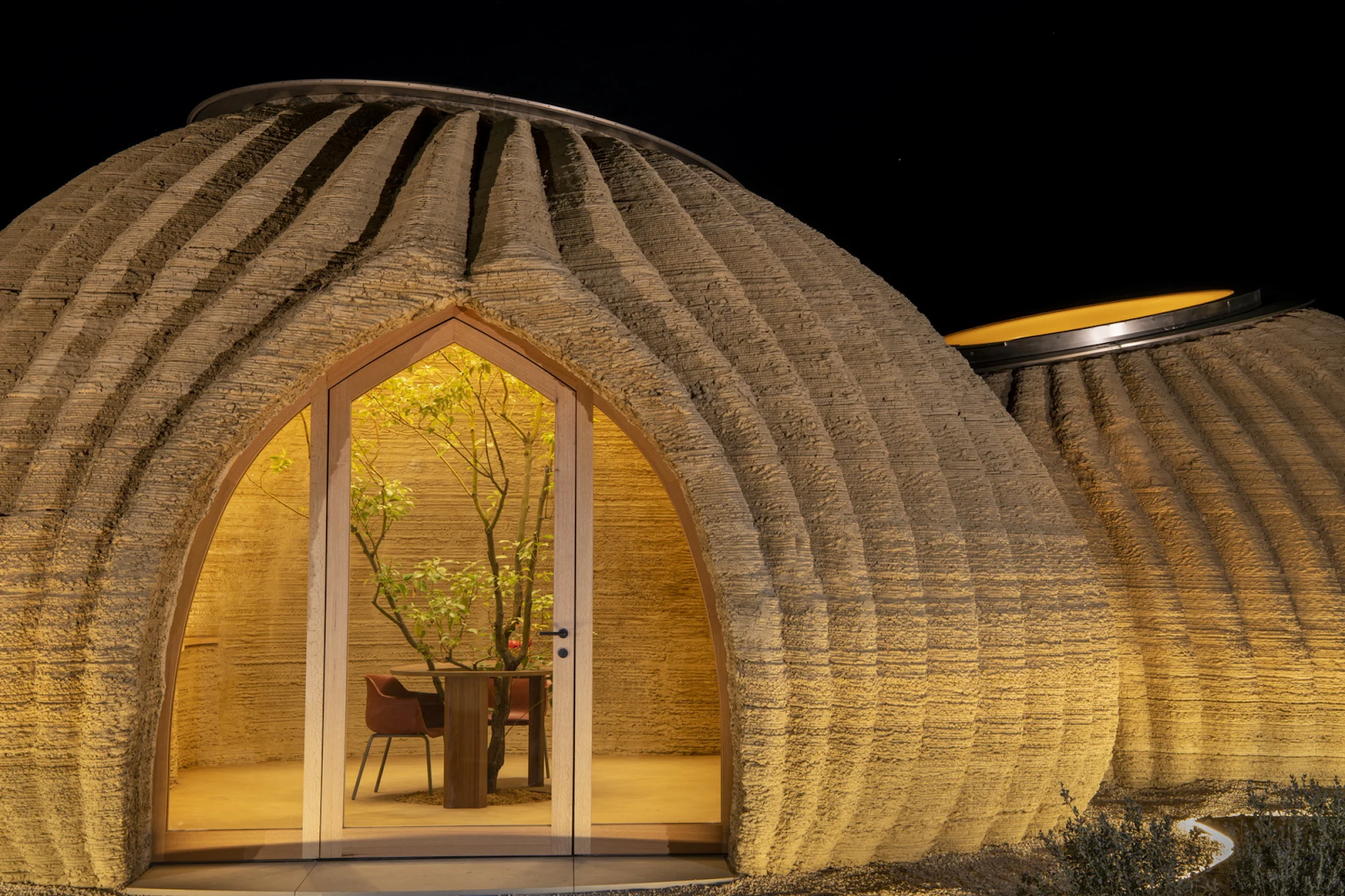
Tecla House (Italy) — 3D-printed clay building made with local soil, designed for thermal comfort.
Source: CNN
3. Rugged Design
It is engineered on the vision to reduce its dependency upon heavy machinery or trained operators. Flat-pack or prefabricated types enable fast deployment in remote or under-equipped areas, and the designs are adaptive enough to be configured spatially and culturally. This design has to be ready to encounter any environmental circumstance that it comes across.

"Arctic Wind-Resistant Prefabricated Homes Designed to Endure the Extreme Alaskan Climate"
Source: Alaka Structures
Government Guidelines & Restrictions
In Charlotte, modular homes are governed by ordinances but regulations as well as enforcement are very different between locations. Building code as well as zoning ordinances at Charlotte will typically exclude nonconventional homes by calling for permanent foundations as well as whole connections with utilities. Modular homes are permitted by Article 14.7 of Section 6 of the Unified Development Ordinance (UDO), but are obliged to stay at least 5-acre sites. The minimum 5 acres serves to encourage neighborhood personality as well as to regulate density.
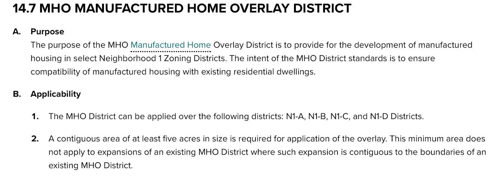
Restrictions under the UDO or the Unified Development Ordinance
Source: UDO
Permanent structure national code does not exist at Senegal, but enforcement is usually poor at rural sites where modular houses are most suitable. To make up for this, modular designs will therefore need to be adaptable—such as utilizing modular foundations at Charlotte and phased build-out with local approval at Senegal. Compatibility with officials and zoning as well as policy of houses diminishes regulatory issues while being within legal and safety range.
Beer Sheba
During my trip to Senegal, we visited an area named Beer Sheba, which was an off-grid area that prioritized the needs of the villages by providing jobs for others. In Senegal, Dakar is the main city that influences most of the population and causes people to move there, but in the village areas, there are fewer and fewer people because they are moving away. But the Beer Sheba Project influences people to stay in villages and produces afforestation that causes a forest to form and farmland to sprout up from dry and barren land. All this is said to say that they don't have a power grid that is connected with the city, rather, the entire idk how much land is powered by solar panels and wind energy.

A clip from a video on the land of Beer Sheba
Source: Beer Sheba Agroecological Center
So, another inspiration for this project is to help the environment and to reduce the costs of living by creating a mechanism that harnesses the wind and the sun. But the costs of installing solar panels can be very heavy, especially for those who are under the burden of homelessness. So the ROI, or the return on investment, has to be high to even begin reasoning for the solar/wind energy mechanism.
Fusion/Reference Sheet
Fusion Setup
Navigate to Autodesk.com and click on the Education tab after you get to the homepage

After the education tab comes up, scroll down to see the products

After you scroll down, move on to the tab where you select a product, and sign up with a student account

For this instance, choose Fusion in order to move on with this project and design.

Once you get to the Subscription plans choose the Student plan in order to get access to products.

After the student account is selected, fill out the information needed for a student account including a student id and then download the product in order to be ready for CAD.

Reference sheet:
The purpose of this reference sheet is to serve as a guide and point of reference whenever these terms are mentioned throughout this document.
Sketch
In order to create a sketch, ultimate document has to be created and stem will at the top left hand side of the screen as shown in the image

Then, after you create the sketch, different shapes and other drawings. After the sketch is finished, press the check mark in the top right-hand side of the screen.
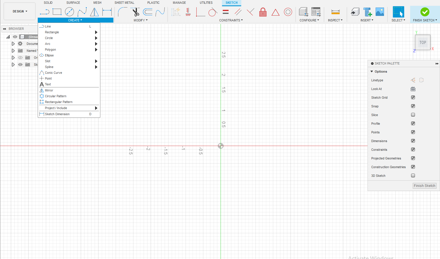
For example, you can start by creating a rectangle. After selecting the rectangle tool, click and drag to define the shape and size, then click again to finish the sketch.
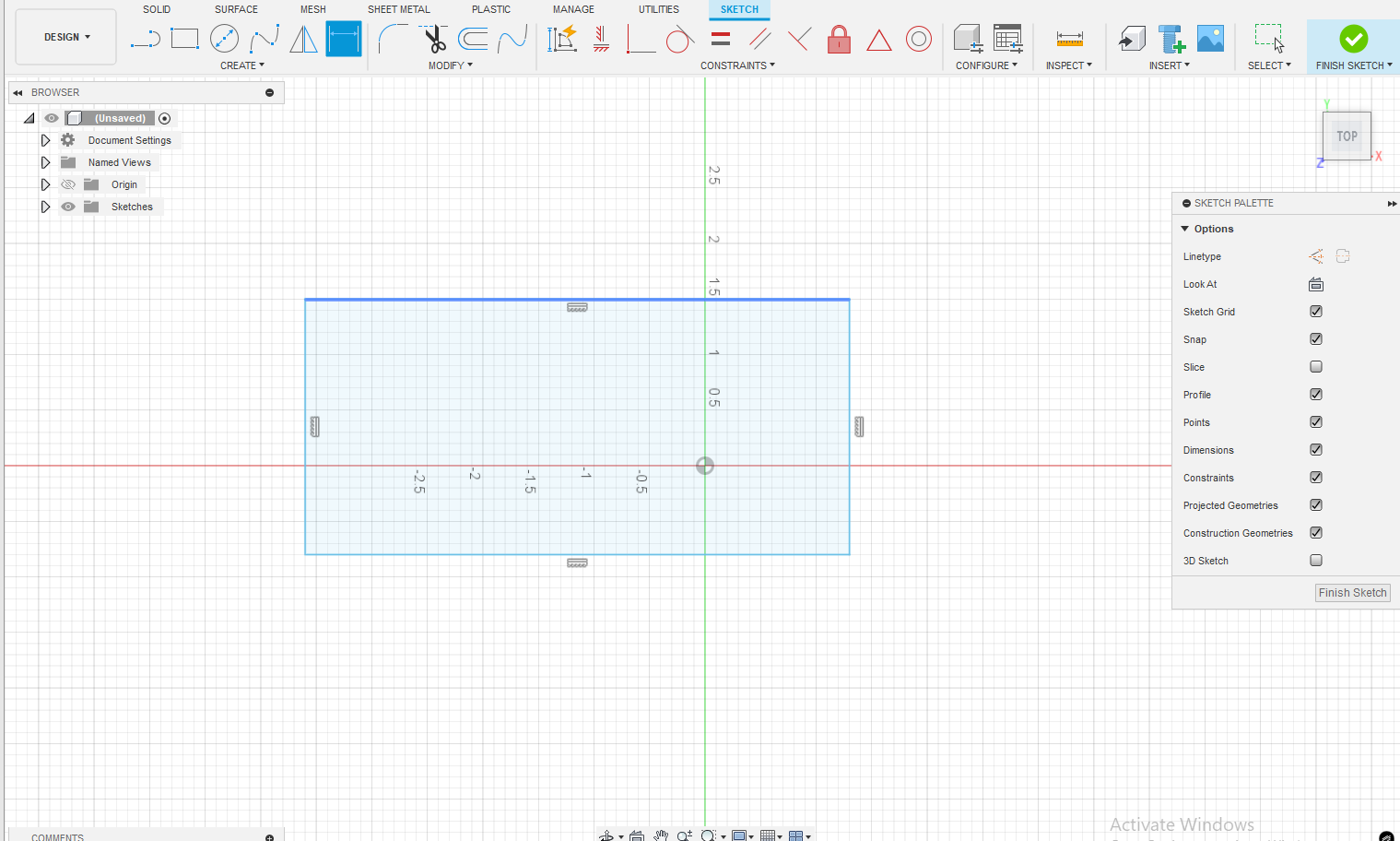
Then you can press D or dimension which help set the lengths for each side of the rectangle. For example the dimensions for this rectangle is 5 inches and 2 inches. After this press the check mark to finish the sketch.

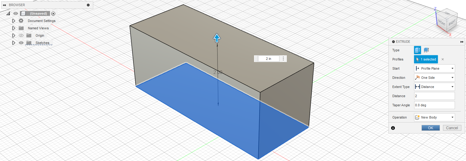
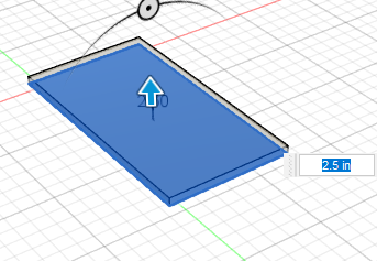
Extrude
To extrude the rectangle, press E on your keyboard or click the “Extrude” button from the left-hand side of the toolbar. Then select the face or profile you want to extrude. The extrude tool allows you to either add material to create a 3D shape, cut into an existing body, or generate a new component, depending on the operation selected in the settings. You can set the height of the extrude too and change if it extrudes one side, two sides, or symmetrically.


Chamfer
The Chamfer function in Fusion 360 allows you to cut or bevel an edge to create a sloped surface. It can be found under the “Modify” dropdown in the toolbar. After selecting the Chamfer tool, click on the edge you want to chamfer. Then, input the desired angle and distance to define the bevel, and press OK to apply the change.


Fillet
Fillet operation under Fusion 360 involves rounding off sharp edges by making the curve have a smooth transition. The operation is found within the “Modify” menu under the top menu bar. After going to the Fillet tool, click that edge to be rounded off. Then type the desired radius for the fillet to change that curve, then click OK to add that fillet.

Slider Joint
The Slider Joint allows two parts to move together with sliding motion, enabling one part to slide in and out of another. You can activate it by pressing the J key or selecting Joint from the toolbar. Then, go to the Motion tab and choose Slider from the dropdown menu to define this type of joint.

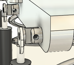
To activate the slider joint, first select the face of the part that will slide inside another component. Then choose the face of the part that will encompass or guide the sliding motion. For example, in the image below, the drill bit can move up and down because it is connected with a slider joint, while the surrounding block holds and stabilizes the sliding part.

Rigid joint
Rigid Joint in Fusion 360 keeps two parts together with no movement of one relative to the other. Permanent joining is achieved by it, effectively treating the two parts as one rigid body. To make a part with a rigid joint, select the J key or Joint from the command bar and select Rigid from the command bar of motion. Now select the faces or points of such parts to be joined together and affirm the joint.
For example, if the drill bit and the base surrounding it (as shown below) were connected using a Rigid Joint, the drill bit would be fixed in place and unable to move at all.

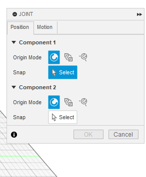
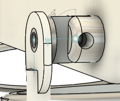
Revolute mate
The Revolute Joint allows two components to rotate relative to each other around a single axis, much like a hinge. It restricts movement to angular rotation while preventing translation along the axis. To create a revolute joint, press the J key or select Joint from the toolbar, then choose Revolute from the motion dropdown. Finally, select the faces or edges you want to connect and confirm the joint.
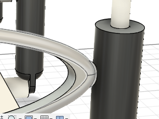
For example, the mounts shown here are connected along the Z-axis and cannot move linearly in that direction, but they can still rotate or move in angular, circular motions.
Middle
To create a rectangle (or any shape) centered on the middle of a side, start by drawing the shape—in this case, a rectangle. Then, from the dropdown next to the rectangle tool, select the “Point” tool if you are manually aligning. Place a point on the side of the rectangle where the alignment will occur. Next, create another point on the side of the shape where you want the new feature to be centered. Use these points to ensure that the new rectangle or shape is placed exactly in the middle of the side.

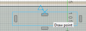

Then, go to the Constraints menu and select the Horizontal/Vertical constraint. Click on both points to align them horizontally or vertically, depending on the orientation of the line. This ensures the shape is centered along that edge. Repeat this process for the line perpendicular to the first one to center the shape in both directions, placing it exactly in the middle of the face.


Initial Designs for “Sunmill”
The “Sunmill” is a name that seems appropriate for a mechanism that operates both on wind and solar energy. The Sunmill Prototype, however, came with a lot of issues. The design for the sunmill stems from sunflowers and their ability to track and follow the sun continuously to optimize their full ability to harness the sun's energy.

An image from a study on why sunflowers follow the sun
Source: UC Berkeley Research
So the idea is for the solar panels to use a hydraulic mechanism with sensors and controllers to sense the direction of the sun. The idea of a windmill should be incorporated within the design. But creating these in two different parts is very costly, so the ideas of a windmill and a solar panel have to be reimagined in order to create a part that provides the highest return on investment.

Initial Drawing for the Sunmill
However, peer review indicated that this design appeared bulky and impractical, particularly due to the oversized fan depicted in the drawing. Additionally, the current layout does not clearly demonstrate how the hydraulic system functions within the overall mechanism.
1.The Solar Panel
The solar panel was created with the thought of modular housing, so the 40 by 75-inch dimensions can fit on each module of the house to maximize the amount of solar and wind energy that is taken in by the Sunmill. By doing this, the owner can adjust the number of solar panels that they want, creating an opportunity for people to save money if they can’t afford the Sunmill despite its benefits.

After this design, the solar panels were extruded by 2.5inches, to show the height of the solar panels the height of the solar panels.
The mounts were designed to attach the hydraulic system to the solar panel. This full-beam design enhances structural integrity by distributing pressure evenly; if each hydraulic unit had its own mount, the increased stress could cause bending and potentially damage the panel. A central slit in the mount allows the piston rod to connect directly.


By extruding the mounts and adding a one-inch hole, the solar panel can pivot side to side, allowing it to continuously face the sun. This hole also enables the piston rod mount to attach directly to the panel. The same mounts must then be duplicated on the opposite side.

With that final hole, the top solar panel is ready for the piston rod mount to be attached. The additional side mounts allow the panel to move freely from side to side without creating excess tension.

Finally, light detectors should be installed on three sides of the system: the north, west, and east sides. These three positions are sufficient to detect the sun’s movement from east to west as well as its position in the north. By sensing the intensity and direction of sunlight, the system can automatically orient itself toward the south, where the sun generally remains highest during the day.
Some might argue that a pre-programmed tracking system would be more effective than using physical light sensors. However, when the sun is obscured by clouds, sunlight is scattered and diffused, making it difficult for purely program-based trackers to accurately follow its position. In contrast, light sensors can detect scattered light beams even under cloudy conditions, enabling more reliable real-time tracking without relying on blind programmed movements.
2. Piston rod mounts(PRM)
To create the base for the piston rod mounts, the exact placement must first be carefully sketched before it is extruded. This base serves as the critical connection point between the piston rod and the solar panel, ensuring stability and proper alignment for smooth movement and reliable operation.

After completing the sketch for the base of the mount, the component that fits into the holder of the solar panel mount must be designed and then extruded by three inches to ensure a secure and stable fit.

Then, the entire base must be extruded symmetrically by 0.5inches to form the section that connects directly to the piston rod, ensuring balanced support and proper alignment.
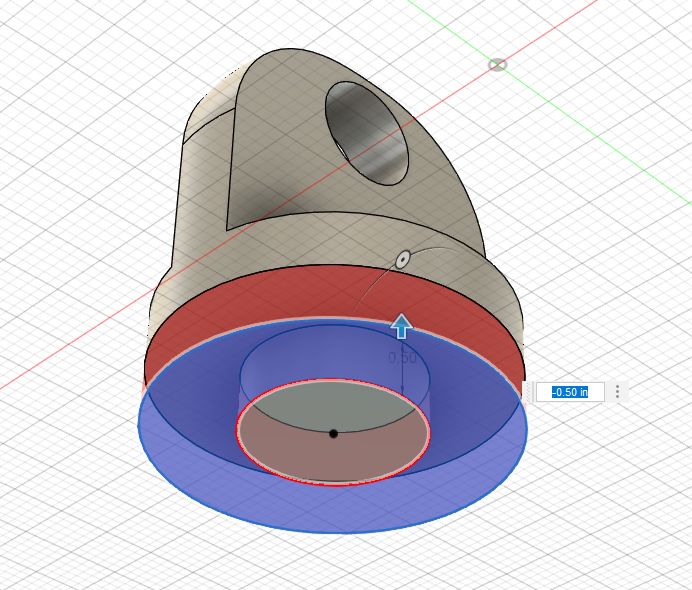
Then, the top part of the piston rod mount (PRM) should be filleted with a 5-inch radius. Next, a sketch should be created on the top surface: it should include a circle with a 1-inch diameter, positioned so that its center is 0.6 inches from the edge, aligned vertically with the midpoint of the PRM’s top.

After that, the hole should be cut through the PRM so that it passes completely to the other side.

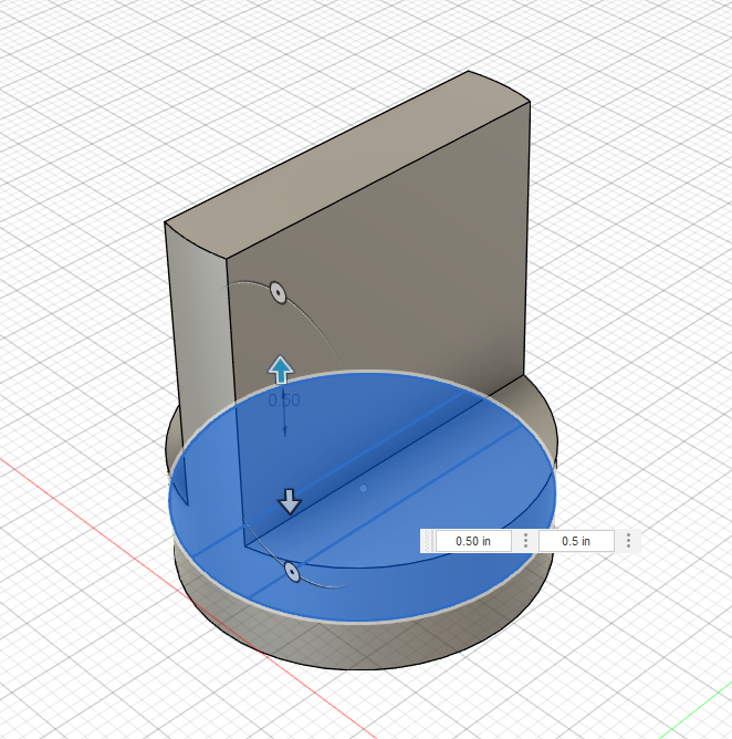
Then, sketch a 1-inch-diameter circle at the center of the PRM’s bottom face. Cut 0.5 inches deep around the outer edge of this sketch. This cut allows the piston rod to connect securely to the mount, which in turn attaches to the solar panel.
Sketch a smaller circle within the existing 1-inch circle, with a diameter of 0.75 inches to create a screw hole. This inner circle will serve as the point where a fastener can secure the piston rod to the mount. Once sketched, cut the hole to a depth of 0.8 inches to ensure sufficient threading or clearance for the screw, providing a stable and durable connection.

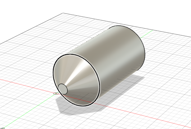
3. Piston cylinder
The piston cylinder serves as the carrier for the piston rod, making it a crucial component in the overall design and operation of the system. Its primary function is to guide and support the piston rod as it moves, ensuring smooth and precise motion. The diameter of the initial extrusion of the cylinder is 4 inches, which provides the necessary strength and stability to withstand the forces involved while maintaining durability and reliability over time.
The inside diameter of the cylinder is 1.5 inches, allowing enough clearance for the piston rod to move freely while minimizing any unnecessary play or wobble that could affect performance. This balance between outer strength and inner clearance is essential for efficient and long-lasting operation. After you create this circle at the top of the cylinder, you cut the cylinder down 14 inches.

To create the bottom mount of the cylinder, start by sketching a circle. Within this circle, add two parallel lines spaced 0.8 inches apart, ensuring they are equal in length and properly aligned. This design will help form the base structure for securely mounting the cylinder.

After that, keep the central rectangular section of the sketch intact, and cut away the exterior parts to a depth of 2 inches. This process shapes the bottom mount and forms the cylinder’s base structure, making it ready for mounting.

Then, sketch a 1-inch-diameter circle at the center of the PRM’s bottom face. Cut 0.5 inches deep around the outer edge of this sketch. This cut allows the piston rod to connect securely to the mount, which in turn attaches to the base.

Finally, for the wing mount, the cylinder base must include a hole to accommodate the fan for wind energy. A one-inch diameter hole should be created approximately 4 inches from the top of the cylinder to allow proper attachment and functionality of the fan.

4. Piston Rod
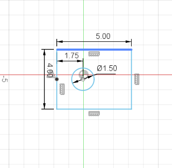
The piston rod is an essential part that is made to fit perfectly within the piston cylinder and is the core of the mechanical function in the system. It is meant to smoothly transmit force and motion within the cylinder for accurate and effective movement. Engineered to be compatible with the internal dimensions of the cylinder, the piston rod provides maximum alignment and stability while ensuring endurance with ongoing usage. The head of the cylindrical tube needs to connect securely to the solar panel mounts. According to the sketch, there should be a 1.5-inch-spaced hole aligned at the center, positioned 1.75 inches from the side. Additionally, a boundary rectangle measuring 5 inches by 4 inches should be included to define the mounting area. Then everything but the circle is extruded 0.5 inches and filleted by 0.2 inches.
For the rod portion of the piston rod, a sketch of a 1.5-inch diameter circle should be created at the center of the head, with its center positioned 0.25 inches from the edge. This sketch is then extruded outward 16 inches in length and inward 1.4 inches to form the rod section.

5. Base
The base of the Sun Mill is the most important component because it houses all the electronics, controllers, and valves necessary for its operation. The base has the same dimensions as the top solar panel, measuring 75 by 45 inches, and features a 5-inch radius fillet around the edges.

After that, the bottom mounts come into play. The sketch must include a central circle with a 3-inch diameter and an inner circle measuring 1 inch that is directly in the center of the rectangle. Then you create two other circles, which you set equal to the central circle and then set apart from the central circle by 30 inches.

6. connections
To ensure the Sunmill can be positioned regardless of the house’s orientation, the design incorporates mounts that allow full directional flexibility. While the optimal alignment is east to west, the hydraulic system enables the solar panel to adjust up to 45 degrees toward the east, west, south, or north. In the referenced design, revolute mates connect the mounts, allowing the panel to tilt and rotate smoothly for maximum sunlight exposure.

The mounts are attached to the hydraulics by screw on the top and bottom panels. The screw on the bottom and the top allow the Sunmill to lean even other than the 45 degrees provided by the top mounts on the side east and west. The cylinder is connected to the base by a revolution, while the piston rod and the cylinder are connected by slider mates.


The hydraulic cylinder itself is composed of aluminum since aluminum can be used for low-pressure scenarios, and the Force required is around 150–300 N (30–70 lbs). Along with that, aluminum is comparably cheaper than other alternatives. But the piston rod has to be composed of a denser material because the pressure on a piston rod is greater than a cylinder that focuses the pressure. So the piston rods can be made from linear motion rods that CNC machines use.
The cylinder barrel has a hole in the side of it so it can fit the fan to harness wind energy. Although not seen, the fan has a bearing that prevents friction, while the cylinder barrel is sealed with epoxy, which prevents liquid from getting out of the cylinder.
7. Fans
While most modern wind turbines use a three-blade design, recent studies suggest that alternative shapes and configurations may be more efficient and cost-effective. The traditional tri-blade structure is expensive to manufacture and maintain due to its size and complexity. In contrast, designs like vertical-axis turbines can be cheaper to produce, easier to install, and potentially more suitable for a wider range of locations. Although wind energy is a cleaner alternative to fossil fuels, its overall costs remain significant. To make wind energy accessible on a large scale, compromises may be necessary—whether in terms of design, materials, or infrastructure—to balance efficiency with affordability.
Source: Power
So, in changing the wind component of the Sunmill, the blades had to be uniquely designed to accentuate the lightness of the wind and enable it to reach its full potential. Their oval shape allows the Sunmill to capture wind from any direction effectively. In regard to the wind component of the Sunmill, the blades are uniquely designed to accentuate the lightness of the wind and enable it to reach its full potential. Their oval shape allows the Sunmill to capture wind from any direction effectively. Also, with the oval shape of the wing, it becomes easier to implement the wing into the overall design of the Sunmill.

Redesign of the overall shape of the fan.
The fan is then extruded symmetrically along with the studs or ends. The studs connect the cylindrical chamber of the cylindrical component to the mount for the fans. After the blades and studs are extruded, they are then filleted so that the studs create a circular shape to help the blades rotate, and the blades are filleted so that they are more aerodynamic and move smoothly through the air, which eventually helps the blades harvest wind energy, which is harvested by dynamos.

After the extrusion and fillet on the outside, the inside can be cambered by 0.5 inches with a 45-degree tilt so that the fan has a pocket in which the air can be caught and moved around in.

Sunmill
The solar system applied for the roof is a hydraulic tracking solar system with 21 panels that enable one day of maximum solar power production. It does not require fixed panel configurations like fixed panel configurations. It constantly changes the inclinations of panels concerning the sun's path so that optimum incidence angles for vertical as well as horizontal axes are attained.

The centerpiece of the system is a Siemens S7-1200 programmable logic controller (PLC), serving as a control unit. In combination with real-time sensor data from 63 sensors spread over each of the three panels that quantify the direction and intensity of sunlight, the PLC and sophisticated PID control algorithms compute accurate positional adjustments to be made to keep the panels in their optimal position relative to the sun.

This image shows the necessary components for a Hydraulic System
The system features hydraulic actuation powered by a small 12V DC hydraulic pump pulling from a closed reservoir through an inline filter to exclude contaminants. Pressurized fluid is routed through solenoid valves to hydraulic cylinders to smoothly and precisely transition solar panel rotation and tilt. Hydraulic actuation does have some ruggedness and force strengths inherent in it compared with electric motors, which make it highly compatible with rooftop installations' weather and structural loads. Year-round dual-axis tracking ability provides optimum energy returns by about 30 to 40 percent more than fixed panel systems.
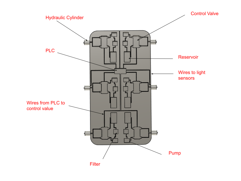
A picture showing the control system at the core of the Sunmill
Greater solar irradiation translates to more electricity generation with quick cash return, combined with further long-term cost savings in energy. Safety features also belong to the control system that will automatically move the panels at night or in unfavorable weather conditions for protection. The total system's approximate cost of roughly $670 is a reasonable investment relative to the energy conservation amounts saved. Economies result from the common use of hydraulic components—i.e., pump, valves, and reservoir—by all 21 panels, thus reducing both initial-cost capital investment and future maintenance. In addition to this, it is also a sustainable and dependable system. The hydraulic system provides robustness and durability, and the PLC provides remote monitoring and diagnostic facilities for the identification of any faulty state at an early stage with rapid rectification. Overall, this solar tracking hydraulic system is a cost-effective and efficient way to achieve maximum solar power output from a home's roof. With built-in precise sensing, smart control, and long-life hydraulic actuation, it delivers continuity of maximum alignment towards the source of solar radiation for increased energy yield along with maximum economic benefit for the lifetime of the system.

A rendered image of the SunMill
Combining wind and solar power generation using a hydraulic system enables round-the-clock and efficient power generation while optimizing return on investment (ROI) by minimizing downtime, material costs, and complexity of operations. Solar panels harness daytime energy, while wind turbines generate output during cloudy or nighttime periods, for a more stable supply. Excess mechanical energy from wind can be stored as pressurized hydraulic fluid to be used later for adjusting the angle of solar panels for optimal sun exposure or augmenting auxiliary functions without further electrical demand. By coupling two sources of renewable energy into one structure with shared foundations, controls, and maintenance regimes, the design reduces capital expenditure while generating greater energy output per square foot, for a shorter payback period and greater.
The Design
The House
Modular houses are a great answer to the problems of affordability, sustainability, and infrastructure in rural and urban areas. Modular houses are built in components off-site and installed quickly, in contrast to conventional building methods. Modularity saves labor costs, reduces waste, and construction time. This allows governments or families to make investments in smaller but essential living spaces, e.g., a bedroom, bathroom, and kitchen, and still have room to include living rooms like the ones above if needs or budgets increase. This step-by-step approach is especially useful in societies like Senegal, where most houses are left unfinished because of a lack of finances, and in cities like Charlotte, where homelessness is a worldwide condition.
In addition to being cheaper, modular homes are also socially and environmentally sustainable in the long run. They can be designed to be responsive to the local climate conditions, such as sandy or clay soil, and can utilize solar and wind energy for sustainability. We already see it happening in places such as Bethsheba, Senegal, where cities exist on renewable energy and afforestation. Modular building also creates local jobs and encourages individuals to stay in their hometowns and invest locally instead of immigrating to overcrowded cities. Modular housing as a whole is an expandable, flexible, and sustainable way of building better communities.
The modular design also allows costs to be lower based on family size. For example, a single person or a couple can live comfortably in just the base module, while a family of three or four can use the base plus the second module. Larger families with more than two but fewer than ten children can happily live in the full house, which includes the base, second, and third modules.
Soundation
While foundations in general are used for the majority of house construction scenarios, they don't fit each scenario in all kinds of environments. For example, houses built by the beach have elevated floors to prevent flooding and storm surges. Conversely, houses built on plateaus typically rest on solid concrete foundations because such areas are less susceptible to natural disasters such as floods. There are Maldivian houses on stilts above the water because the ground beneath them is very shallow. But the issue gets aggravated for houses in regions prone to monsoons, which involve heavy rain and potential flooding. Subsistence farmers form the majority of the population in most such regions, as is the case in most African countries and India. These farmers are often under economic strain as a result of the government policies, crop losses, and the sacrifices that are incurred through agriculture. The use of high housing systems that are similar to stilts or beach houses cannot be feasible or economically possible for these communities with their tight budgets and the specific environmental conditions that they have to endure. Here, other methods unique to their economic and environmental realities are required to build permanent housing that offers shelter during monsoon seasons.
House foundations typically are 3 to 4 feet deep, but they only need to be 1.5 to 3.5 feet deep in Senegal. During monsoons, the soil beneath a house and mushy ground, and thus the foundation would have to be considerably deeper than this suggested length to give strength. is unstable
The Soundation
Since the soil type varies from region to region all over the world, it is extremely important to design a solution that is effective as well as cost-cutting. The Soundation does just the same. The Soundation would be similar to an individualized drill that will penetrate the ground and strike the bedrock layer, ensuring houses are built on a solid and firm foundation.
The internal assembly of the Soundation is a term applied from the robotics community to convert axles. Four rubber wheels rotate a single drill to drill in, and all four wheels are connected by axles that connect to each other using timing belts. This allows customization of the drill itself.
The column was drilled by drawing a circle and then extruding a coil and cutting the coil into the column.

The most superior functions of the foundation are the axles and motor, by which the motor drives the axles to create the movement needed. There are also attachments that are designed to securely hold the foundation against the house to create a secure connection and proper alignment while moving. All of these combined transfer power mechanically while creating a firm, stable connection between the foundation and structure.

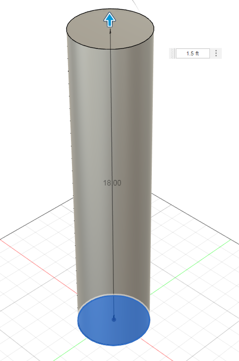
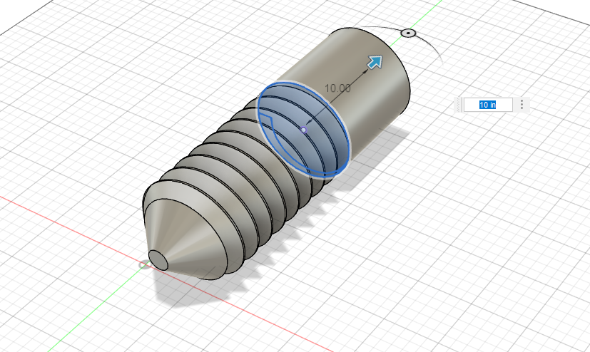
The drill is made by sketching a 10-inch diameter circle and extruding it 20 inches, creating a strong cylindrical body that provides both stability and sufficient length for effective operation.

The other end of the drill bit is chamfered 4 inches at a 45-degree angle, creating a beveled edge that improves durability, reduces stress on the bit, and allows smoother penetration during operation.
Although the drill may appear fixed, key parameters such as screw length, thread spacing, and thread depth can be adjusted to suit different soil types. Using the coil function, the cylinder can be modified to create customized screw threads, optimizing performance based on local soil conditions.
e.

Then, extrude the other end of the drill bit as a smooth, thread-free section. This part acts as an automatic stopper, preventing the drill from going too deep while allowing the threaded section to dig into the ground effectively. This design helps control drilling depth and protects the structure during installation.
Following the method of using Senegal's soil type map as a guide, a ground-drilling foundation system like helical or screw anchors would bring great improvement in housing stability by penetrating weak surface soils and anchoring deeper into denser layers. The majority of regions, including the Groundnut Basin and ferruginous zones, have sandy or sandy-clay soils that move, and floodplains and coastal zones with hydromorphic or salt-containing soils are prone to waterlogging and erosion, and thus shallow foundations are not dependable. By installing deep, corrosion-resistant screw piles or similar drill-in support systems, homes can be able to resist settlement, remain stable during seasonal inundations, and be safe against soil erosion, ensuring a stronger and more durable solution for a broad range of Senegal's different soil conditions.

Soil types across Senegal
Source: Research Gate
A 20-inch screw in Mecklenburg County soil would extend beyond the loose surface layer into the dense Bt clay horizon. This clay’s firm, cohesive nature provides strong lateral resistance, allowing the screw to achieve excellent holding capacity. Once it engages that compact layer, movement and loosening are minimized, making it highly suitable for stable modular housing foundations.
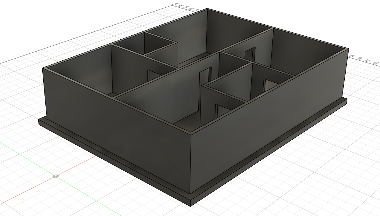
First Module
Base Model
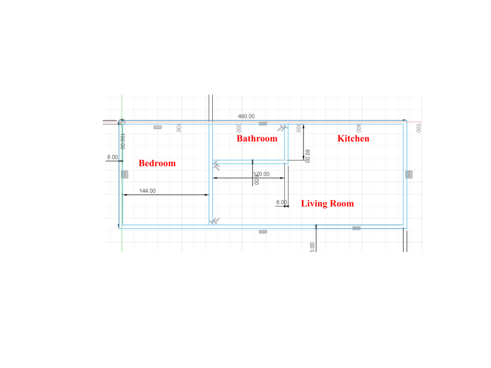
The base model consists of one bedroom, a living area, a bathroom, and a kitchen with the dimensions listed below. This design creates a compact yet affordable space without sacrificing essential features. The base version of the tri‑modular structure is suitable for one to two people but not for a larger family. Its footprint measures 480 inches by 60 inches, which equals 200 square feet. The walls are placed with a thickness of six inches, which is considered optimal. The bathroom includes a compact shower and toilet, while the bedroom is sized between a master and a guest bedroom. The kitchen is relatively large, and the living area is compact but functional.
Having established the plan, the walls are extruded 9 feet high to establish the vertical shape of the model. With the walls in place, a subsequent extrusion of 1 foot is performed at the base to establish the floor plate. The operation establishes the structural stability, creates a clear separation between the foundation and the occupiable space, and develops the support for interior finishes and services.

Next, the doors for each room are created, with standard dimensions of 3 feet in width by 7 feet in height. These measurements provide comfortable access while maintaining the compact design of the structure. With the bathroom door being 12 inches from the right side and bedroom door being directly in the middle and connecting to the ground.


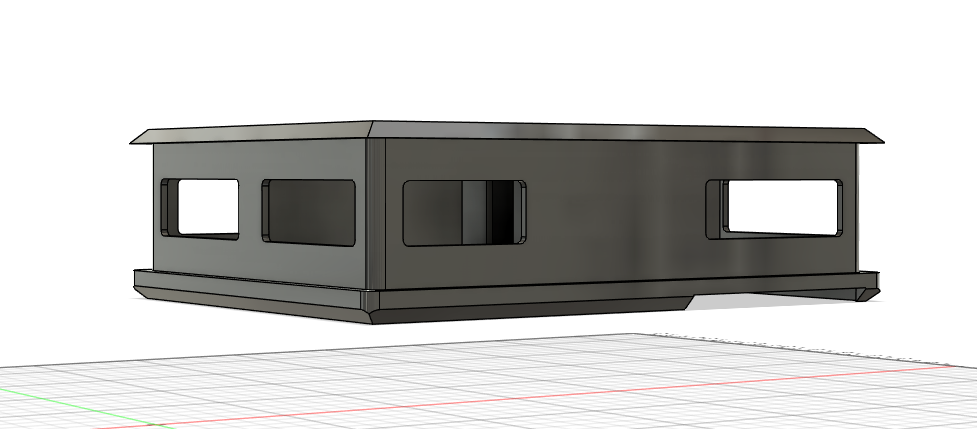
After that, windows are added to each side of the base. Each window maintains uniform dimensions of 47 inches in height and 100 inches in length, with a 5‑inch fillet applied to the corners to create smooth, rounded edges. The windows also improve natural lighting in the house that help the homeless handle energy bills better.

On the front side, include one window frame with the same dimensions as the previous windows, positioned horizontally in line with the center of the base and placed 24 inches away. Next to it, add a larger window designed to facilitate the connection between the base and the second module. This larger window spans the full length of the wall and integrates with the glass panels, emphasizing a modern aesthetic while improving natural light within the base module. However, for the window located at the far right, its opening must extend completely through to the opposite side of the base module to ensure proper alignment and functionality.

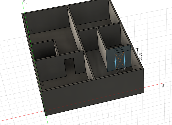
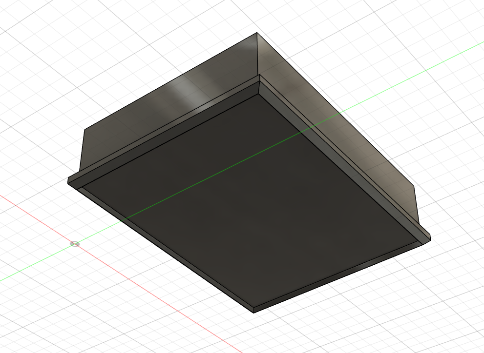
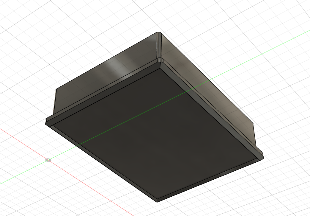
Extrude the base module’s top surface by one inch to create the roof, then add a 72-inch diameter circular opening for a space-saving spiral stairway leading down to the kitchen. Position the circle so its center is horizontally aligned midway between the purple line and the bathroom’s far right wall, ensuring it fits without obstructing walls or fixtures.

Afterward, fillet the edges with a 10-inch radius. Then, add mounts for the foundation that are 3 inches in diameter, positioned 11 inches from the nearest edge and 6 inches above the ground. Repeat the same step on the opposite side, mirrored.

Second Module
Module two:
Upon the flexible build of the base module, Module Two provides additional living space for growing families. By adding this second module, three- and four-member families have additional rooms and functionality at a fraction of the cost of an entire house. This offers the flexibility needed to maintain costs while adapting to changing needs, and therefore is an ideal step up for those requiring additional space but not ready for the whole three-module home.
In a separate document, insert the base module for reference. This allows you to create the second module without needing exact measurements from scratch. The purpose of this step is to construct the first wall of the second module while also creating an opening for the large window or stud.
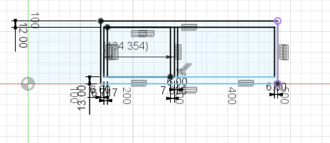
After extruding the back and side walls by __ inches, also extrude the large window stud and the surrounding window panel studs by the same amount. This ensures a secure interlocking connection with the base module, providing structural stability and proper alignment between the modules. By extending these studs, the second module will fit snugly onto the base, minimizing gaps and reinforcing the overall integrity of the modular assembly.
The second module features a bedroom along with an extended living area, providing additional space and comfort for growing families while seamlessly integrating with the base module.
Then, create two windows using the same dimensions as the previous windows. Align them horizontally so they are centered on either the right or left side of the designated section (sketch area). One window on the west wall and one on the north wall.
After the final wall of the second module is constructed, the opening to the house can be decided. Begin by creating two vertical glass walls, one on each side of the centrally positioned door, to give it natural light without making it asymmetrical. Across the door, fit a wider horizontal panel of glass that spans the door width, adding more visual openness and extra daylight to the interior. Together with this, this combination presents an appealing entrance and adds to the overall aesthetic and lighting of the second module.

While Module 2 and the base module are ultimately connected using rigid joints during final assembly, it is essential to design these joints to ensure both structural stability and ease of alignment. The joints should provide a secure fit that prevents lateral movement and maintains a tight seal between the two modules. At the same time, their configuration should allow for efficient installation, minimizing the need for extensive on-site adjustments. Properly engineered rigid connections not only enhance durability but also help the modules function as a single cohesive structure once assembled.
Third Module
Final Building:
The third module completes the full home design, making it suitable for larger families with more than two but fewer than ten children. Building upon the base and second modules, this addition provides expanded living areas, additional bedrooms, and increased functionality, transforming the structure from a compact home into a spacious multi-room residence while maintaining the modular system’s cost efficiency and flexibility.
The second floor, which serves as the third module of the modular house, includes two bathrooms, three bedrooms, and a designated area for the staircase. Additionally, it features a loft space designed for relaxation or multipurpose use, adding comfort and functionality to the overall home layout. With dimensions for every room below in a labeled order.

After the walls are extruded by one foot, begin positioning the doors. Each door maintains the same dimensions as before: 7 feet in height and 3 feet in width, with the bottom edge aligned to the floor and centered on the wall panel where it is placed. All doors share the same design, except for two cases: the second bathroom door and the north-side doors. The north-side doors are positioned so that their centerlines are exactly 4 feet away from the nearest wall. The second bathroom features a Jack-and-Jill door configuration, which saves space and allows Bedrooms 4 and 5 to share access to the same bathroom efficiently.

After the main floor walls and the doors the next part is the attachment to the seocnd module and the main module so a rectangle must be created that is a foot out on all sides and then extruded by 13 in down.
After that, another sketch is created in order to cut the bottom mount and make space for the base and the second module. The rectangle that is used to cut is 485 inches in width, and the height is 373 inches which is then cut out from the extrude. After that, there is a chafer on the four corners of the rectangle by 11in at an equal distance. Then all the sides are filleted by 10 inches.
The fundamental measurements for the windows remain consistent with those used in previous modules to maintain uniformity across the entire house design. However, the windows in individual bedrooms require slight adjustments to accommodate the specific dimensions and layout of each room or labeled “Room”. These windows are typically positioned approximately 1 to 2 feet from each adjacent wall, allowing for balanced spacing, improved natural light distribution, and sufficient wall area for furniture placement or additional design elements. This placement strategy ensures that the windows are functional while maintaining aesthetic consistency and structural integrity throughout the modular design. After all the windows are created filet the windows by 5in.


After completing this step, cut the roof edges at a 45-degree angle, removing 12 inches from each side to create beveled corners. Next, add a rectangular cutout measuring 16 inches by 186 inches. This opening ensures that the entrance structure can fit properly within the roof design, maintaining both accessibility and alignment with the module’s overall layout.

Finally, for the window detailing, create a rectangular sketch that extends 6 inches beyond the window opening on all sides. Extrude this sketch by 4 inches to form the outer frame. Once extruded, apply a 5-inch fillet to the edges to achieve smooth, rounded corners, enhancing both the structural finish and the overall appearance.

Entrance
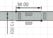
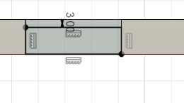
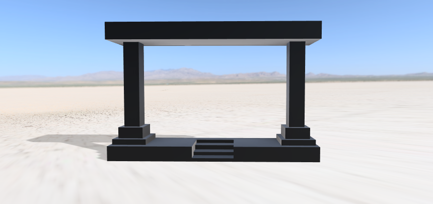
First, create the base of the structure using a rectangle with dimensions 13 by 184 inches, and extrude it by 40 inches. Next, sketch the first base for the beam by drawing a square (30by 30 inches) positioned in the middle of the base but offset from the edge by 2 inches and extrude by 5 inches. Sketch the second base for the beam by drawing a square (26 by 26 inches ) positioned in the middle of the base and extrude by 10 inches. Then, create the vertical column with dimensions 26 by 26 inches, and extrude it by 77inches. Repeat these steps on the opposite side of the base to create the second column. Finally, create a roof for the entrance that is identical in size to the base and sits across the two columns.


Then, create a rectangle with dimensions 36 by 13 inches in the center of the north side of the base. Cut this rectangle all the way through the base to form an opening. Next, create additional rectangles of the same size attached to each side of the cutout, with dimensions 10 by 36 inches (reduce height 3 inches with every step, there should be 4 steps), and extrude them by 10 inches. Repeat this step for every level or segment where this detail is needed.

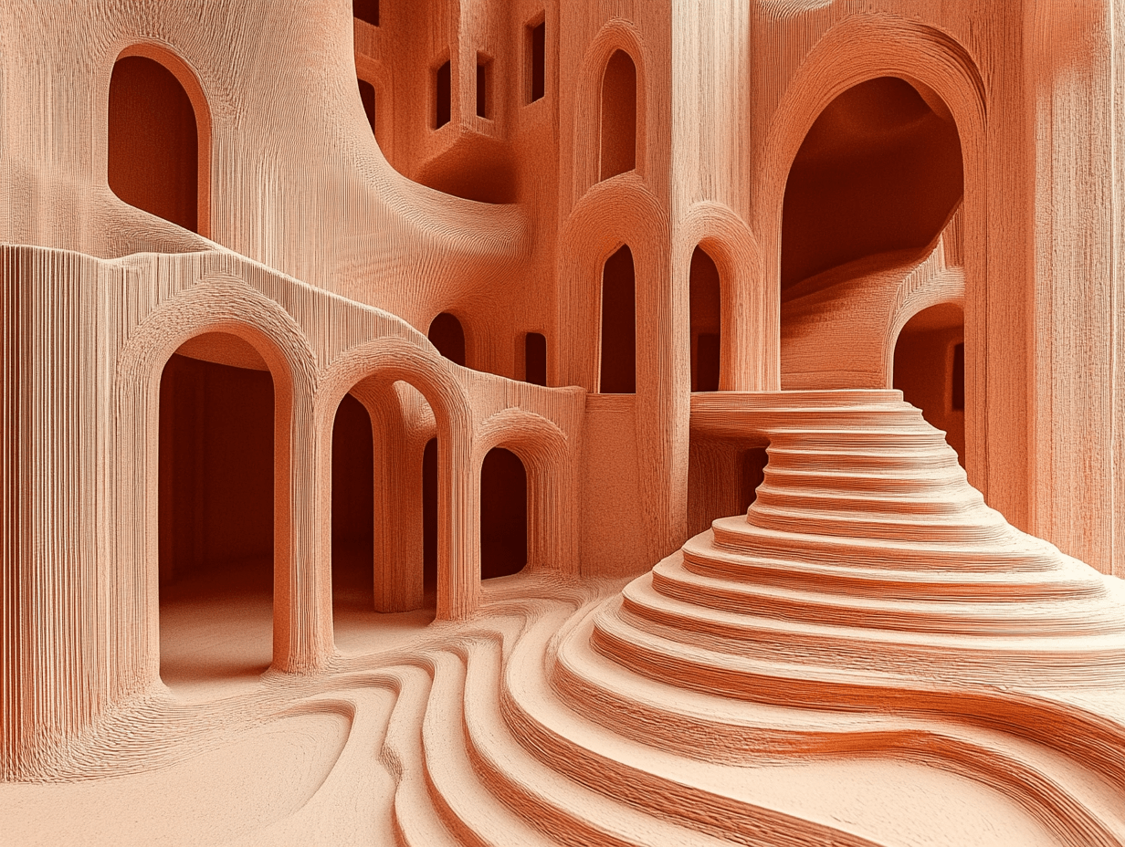
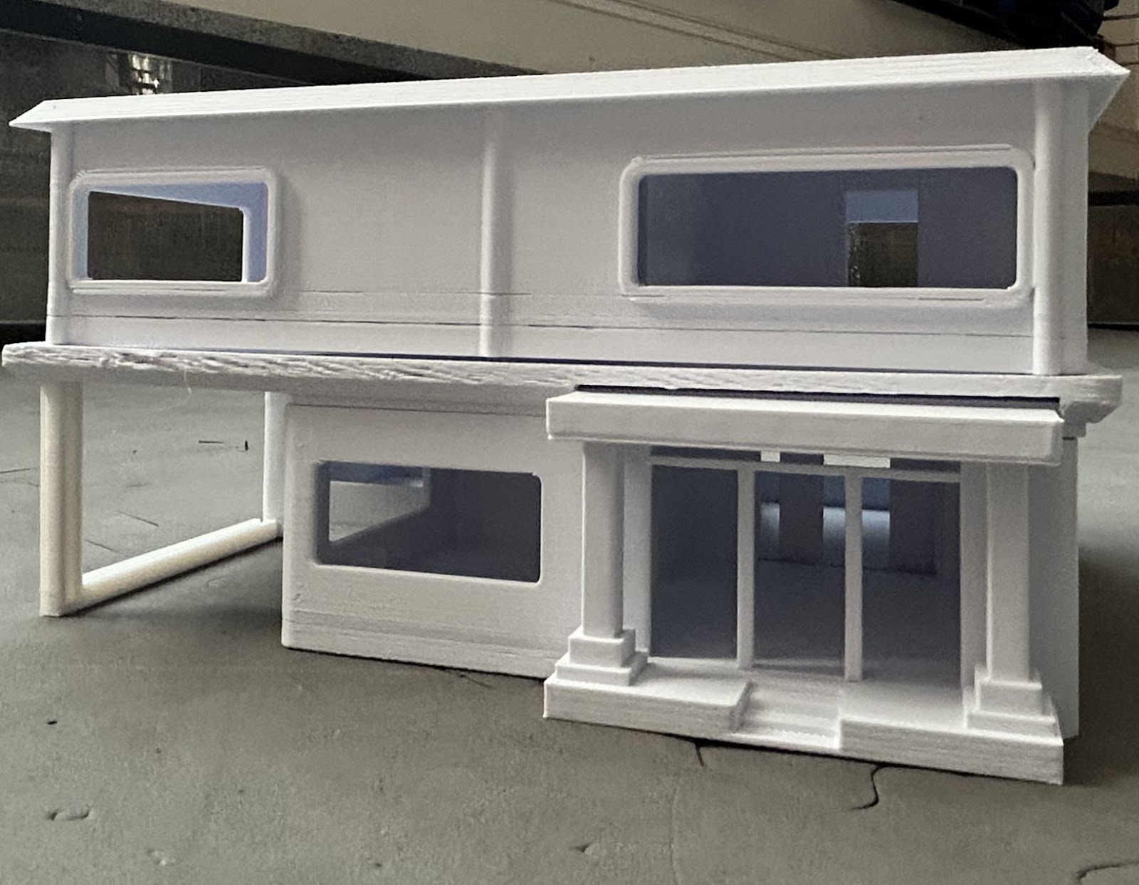
Rendering
All of these parts are connected by rigid joints that bring all the components together in a different tab in order to look like the image below.

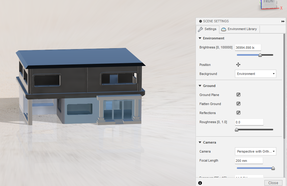
Then you can render the whole house after adding in the sound and the sunmills by selecting a background, adjusting the lens, and the lighting.
Add the solar panels and the foundation.

Materials
Within this modular housing scheme, the choice of material is key to how the scheme will be affordable, environmentally friendly, and well-designed. The newest method could potentially be onsite 3D printing using soil composites that are able to print structural elements and walls directly from on-site materials. This eliminates transport costs by far, decreases carbon footprint, and makes it possible to build on a large scale in inaccessible or resource-poor areas. Drawing from what is available in the environment, the process provides a closed-loop system in line with long-term sustainability objectives.
An image of the world's first onsite global 3d printed house with organic material harvested from site.
Source: CPT Worldwide
Senegal's soils contain sand with sufficient clay that can be blended together with water and natural materials like straw or any other plant reinforcement to produce a printable, hard compound. The blends can be molded into dense load-bearing walls that tend to modulate indoor temperatures naturally by cooling the inside during the day and warming it during the night. This passive temperature response lowers mechanical cooling and heating needs, conserving energy demand.

Source: USDA
Charlotte’s soils contain very high clay content that can be stabilized using lime or other additives to make them hard and water-resistant. The top layer, known as the AP horizon, is an 8-inch-deep plowed surface horizon, but is quite brittle. Below this is the Bt1 horizon, found between 8 and 17 inches deep, characterized by yellowish-red clay, indicating a higher clay content. The Bt2 horizon follows, similar to Bt1 but more compact and brownish in color. Beneath that lies the BC horizon, from 25 to 36 inches deep, containing less clay than the Bt horizons. Finally, the C horizon, extending from 36 to 60 inches, consists of highly weathered, brittle rock.
In North Carolina, clay extracted from the Bt1, Bt2, and BC horizons (up to a maximum depth of 36 inches) can be used to produce clay suitable for 3D printing prefabricated houses. This printing technology adapts to different soil mixes, making the appearance regionally appropriate while maintaining structural integrity. Additionally, this method allows for training local workers to produce building materials directly from the ground, supporting the local economy and building community skill resilience.
Budget
This housing complex offers an extremely low-cost solution to homelessness, the whole unit priced at $148,870. Because it is module-built, units can be deployed in flexible arrangements. Module 1 (bath, kitchen, 1 bedroom) for $18,000, Module 2 (additional bedroom) for $12,000, and Module 3 (4 beds, 2 baths, 2nd floor) for $66,000.
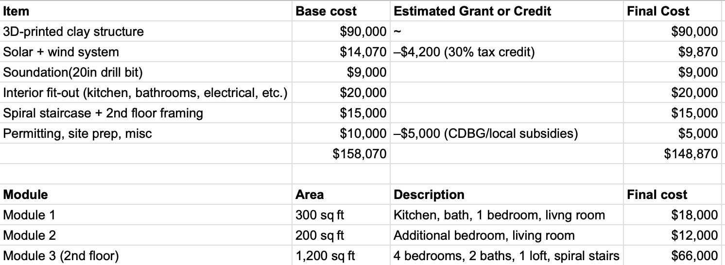
A major factor in this affordability is the way grants are utilized and cost-cutting practices specified in the budget. The solar + wind system, which costs $14,070 at baseline, is really reduced to $9,870 following a 30% tax credit of $4,200. Far more significant to homelessness programs, the permit, site preparation, and miscellaneous costs of $10,000 are reduced by half to $5,000 because of an estimated $5,000 from CDBG/local subsidies. These grants are particularly to be used in the support of community development and affordable housing for those in need, directly going toward efforts to house the homeless. Through the use of these grants and efficient construction methods, along with the flexible modular pricing, the project significantly eliminates the cost barrier to providing stable, sustainable shelter.
3D Soil Printing
- Prepare the Clay: Collect local clay, remove impurities, dry it, and grind it into a fine, consistent powder.
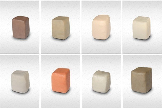
Source: Eazao
While preparing the clay for 3D printing, always look for a less sticky one that has a good texture and dries quickly. Also, while using a screw print head for printing, do not use anything that is too rough to avoid the screws be wearing out soon. The clay used for printing must be soft to be injected into the machine. Make sure to choose a clay that absorbs water but is not too saturated.
- Mix and Extrude: Combine the clay powder with binders, fillers, and water to create a printable composite, then extrude this mixture into filament using a specialized extruder.

Source: ScienceDirect
There are two kinds of materials used in 3D soil clay printing (powder and binder) in which binder is usually a liquid form material and acts as an adhesive to support bonding the powder layer at very low temperatures. These can then be used as clay filaments to print parts that are heated to around 2000°C, followed by curing, to cure the binder and improve the strength.
- 3D Print the Structure: Load the clay-based filament into a compatible 3D printer and build the house layer by layer, followed by curing or drying to harden the printed structure.
Source: Illustrarch
3D Printing
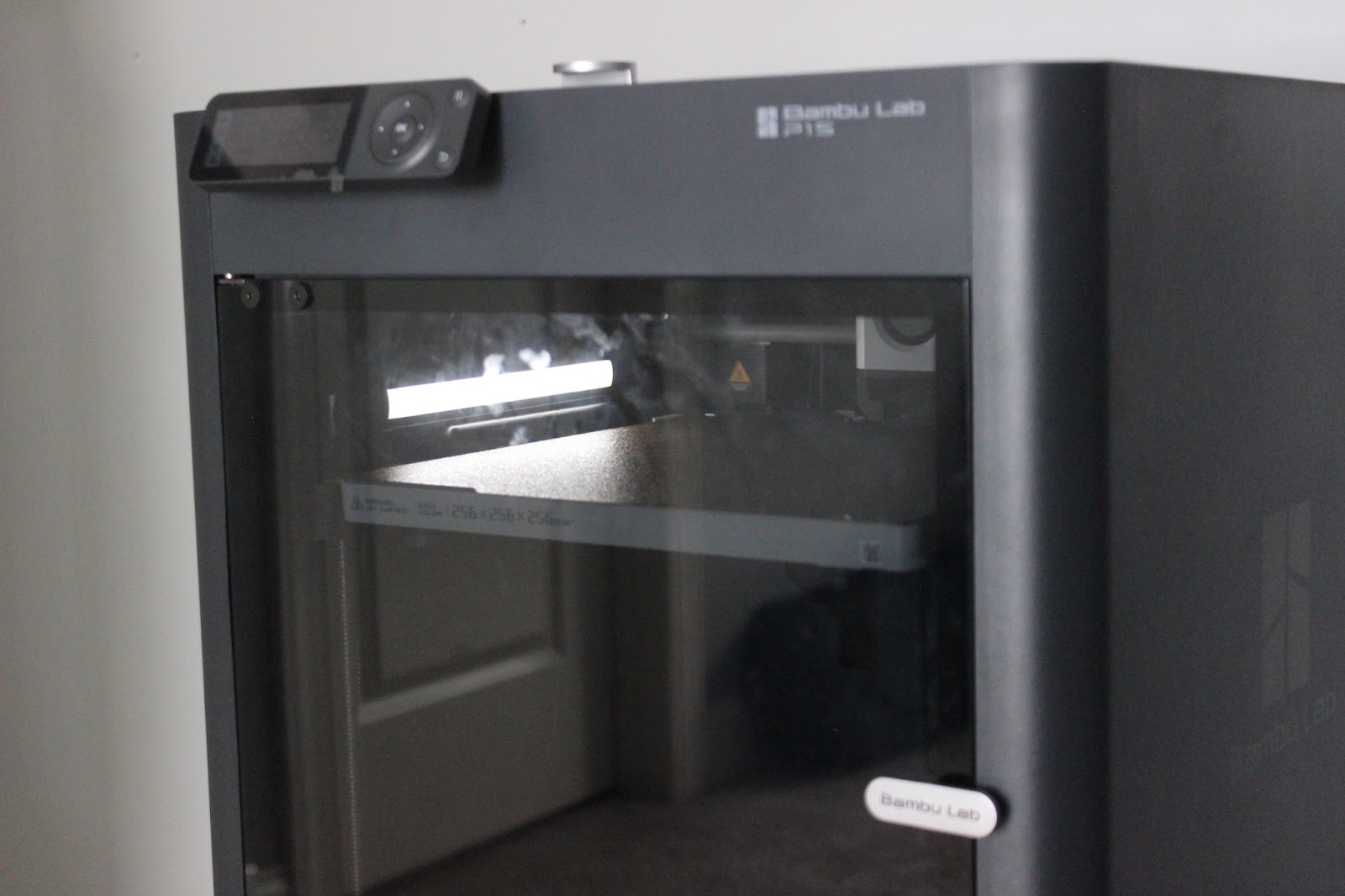
In order to manufacture the parts needed for testing the physical model, a 3D printer was required to execute the designs. I used our robotics team’s 3D printer, the Bambu Lab P1S, to fabricate these components. This process not only allowed me to create the necessary test pieces but also provided insight into the layer lines that would appear in construction if a full-scale version of the model were produced. The Bambu Lab P1S has a print volume of 10 × 10 × 10 inches, which makes it possible to produce a scaled-down version of the design. For this project, the model was printed at approximately 1.5% of the original structure’s size, allowing for manageable fabrication while still capturing key details of the full-scale concept.

Slicer:
Depending on the specific 3D printer being used, you need to download the appropriate software to prepare—or “slice”—the parts and components for printing. For example, my team uses a Bambu Lab printer, so we export the models from Fusion and then process them using Bambu Studio to generate the necessary print files.

After you download your slicing software, create a new project.
Preparing
Then, import the part into the slicer by clicking “Add” and selecting the desired file.
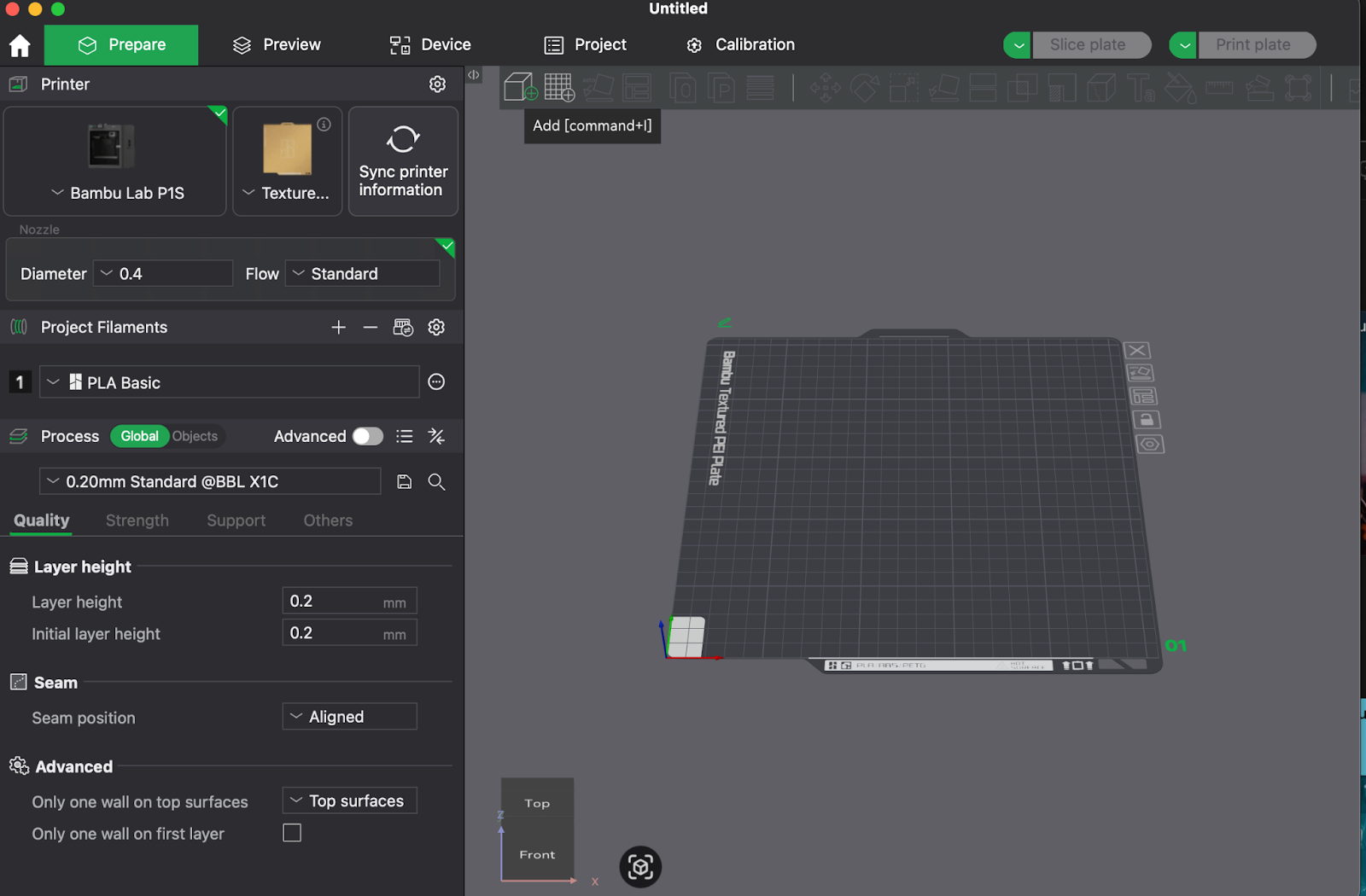

Then, use the slicer’s auto-rotate function and enable supports to prevent deformation during printing. Set the arrangement option to “0” so the software automatically positions all objects for optimal layout.


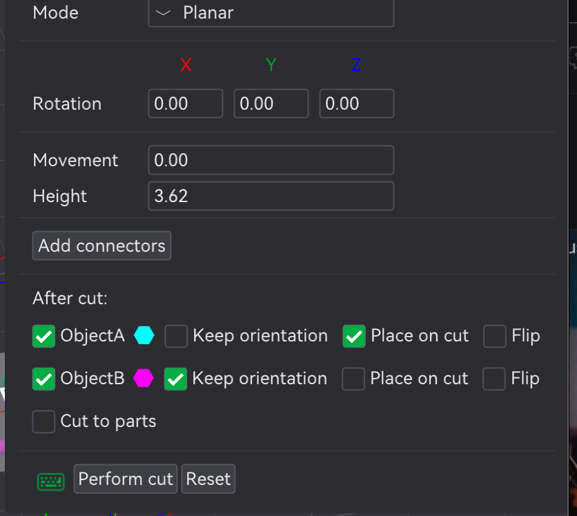
For all of the modules use the perform cut module to cut off the roof and print separately in order to save time and support.
Slicing
After this, select “Slice Plate” so the software can generate the G-code, which essentially provides the printer with detailed layer-by-layer instructions. Once slicing is complete, connect to your printer and send the files over for printing.

Printing
After completing calibration and pre-print checks, the printer begins the job. The progress can be monitored in real time through the software, which provides live updates and access to the built-in camera feed. This allows you to watch each layer being printed, verify adhesion, and ensure there are no issues such as warping or failed supports. If necessary, you can pause or stop the print remotely to prevent wasted material or time.
Onsite Assembly
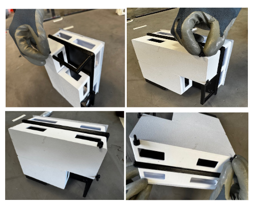
Step 1: Prepare and Sand the Module Components
Prepare the components of the first module of the three-module home by carefully sanding the edges and contact surfaces of both the base and roof to remove any rough edges to ensure a precise, snug fit when the roof is placed on the base to reduce gaps and increase stability. See the diagram below for reference.

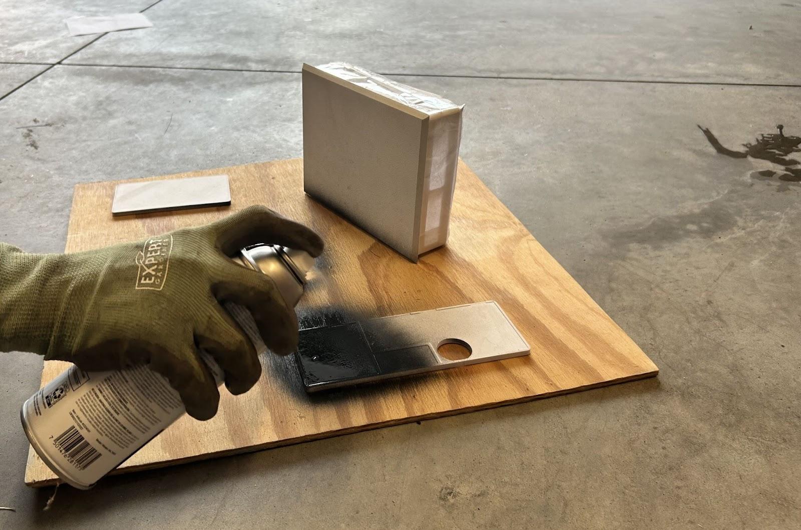
Step 2: Paint the Roof Black for Solar Efficiency
Once sanding is complete, apply a black coat to the roof of the first module (from Step 1) and paint it black. This allows the roof to absorb the sun’s rays because black absorbs light rays to maximize the amount of solar energy captured, enhancing the efficiency and energy production installed on top.
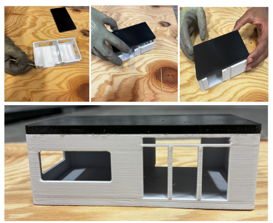
Step 3: Prepare Module 1
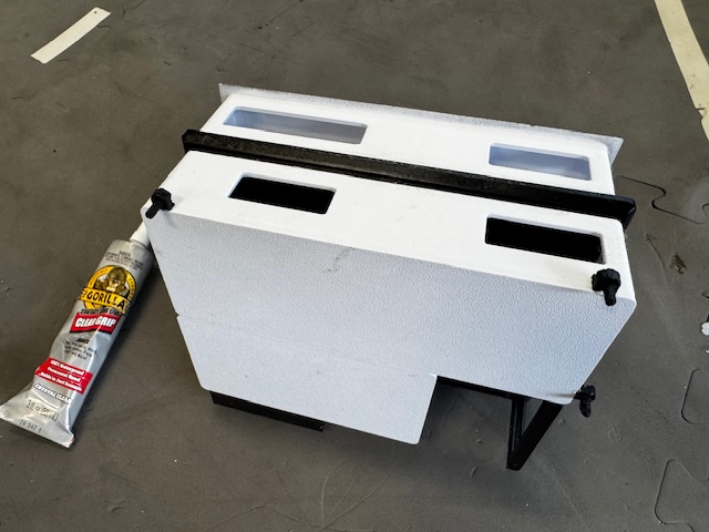
Attach the roof and the base of the first module to complete the first full module. The roof and the base were printed separately in order to reduce the print time.
This is done by applying a thin layer of strong glue along the edges of the base by using a toothpick to carefully spread the glue, keeping it within the bonding surface to prevent overflow. Once glue is applied, gently lower the roof onto the base, making sure edges line up precisely, and apply light, even pressure around the perimeter to ensure full contact.
Finally, inspect the edges to make sure that no glue seeps out, wipe away with a tissue paper before it sets, and allow the module to cure to give enough drying time to complete the first module.

Step 4: Prepare Module 2
Prepare the second module by following the same instructions from Step 3 by applying a thin layer of strong glue along the edges of the base using a toothpick to carefully spread the glue, keeping it within the bonding surface to prevent overflow.
Once glue is applied, gently lower the roof onto the base, making sure edges line up precisely and apply light, even pressure around the perimeter to ensure full contact.
Step 5: Attach Module 1 & Module 2
Module 1 & Module 2 were created separately but with perfect precision to fit each other with edges aligned but in tangent ways, as you can see below, with one complementing the other.
Apply glue on one of the edges of Module 2 as shown in the figures below and let it dry for a few minutes to secure both modules.

Step 6: Prepare Module 3
Module 3 was carefully planned and split into two: the First part being the floor, and the second part being the walls and the roof.
The first part is painted in black underneath to align with the overall house color.
Apply glue to the edges of the roof and secure Module 1 and Module 2, let them dry for a few minutes.
Bring both Module 1 and Module 2 under the roof and secure them precisely, and apply light, even pressure around the perimeter to ensure full contact.
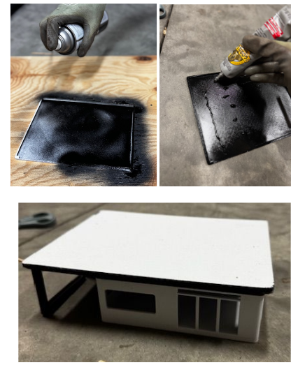
For the second part, first secure the sides with paper to ensure the black paint doesn’t spill over, as given in the pictures below.
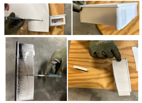
For the second part, safely apply glue over the roof to secure Module 3 to fit with Module 1 & Module 2. This was done with a segmented approach to ensure each Module serves its own purpose and can be integrated/disintegrated based on the family's needs.
A pillar is also added to give extra support to the structure (refer to the 2nd figure below)


Sunmill
Step 7: Prepare the Soundation
For the final step to prepare the soundation, glue the 3 corners and secure it tightly as shown in the pictures below.
Scale model:
The online scale model in Fusion 360 is scaled down from 100:1.5.
Location
While testing construction in Senegal may currently face challenges due to untested conditions, similar circumstances can be effectively modeled and tested in Charlotte. Specifically, Mecklenburg County in North Carolina offers a suitable environment for this, as many areas have soils high in clay content, making it a viable choice for building these homes.
For optimal use of space, these houses should be constructed on plots of at least 1,500 square feet, allowing for comfortable living areas. Additionally, spacing between homes and roadways requires approximately 600 square feet more to ensure accessibility and proper infrastructure.
Furthermore, given that over 20% of homeless adults in the region are either unemployed or actively seeking work, it is crucial that these housing developments are located near cities or public transportation hubs. Easy access to transit options will support residents in reaching employment opportunities, promoting greater social and economic stability within the community.
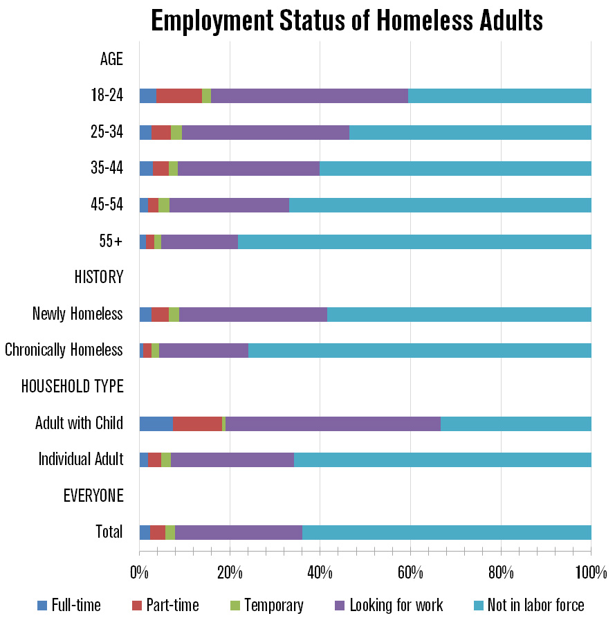
This graph shows that over 20% of the adults who are homeless are looking for work or working.
Source: Economic Roundtable
After extensive searching, we found a 6.1-acre plot of land capable of accommodating approximately 126 houses. Given that each house requires about 1,500 square feet of living space plus an additional 600 square feet for roads and spacing, the total space needed per house is roughly 2,100 square feet. With 6.1 acres equaling 265,716 square feet, this land offers ample room to develop a well-planned community that balances comfortable living areas with necessary infrastructure, making it a promising site to address local housing needs.
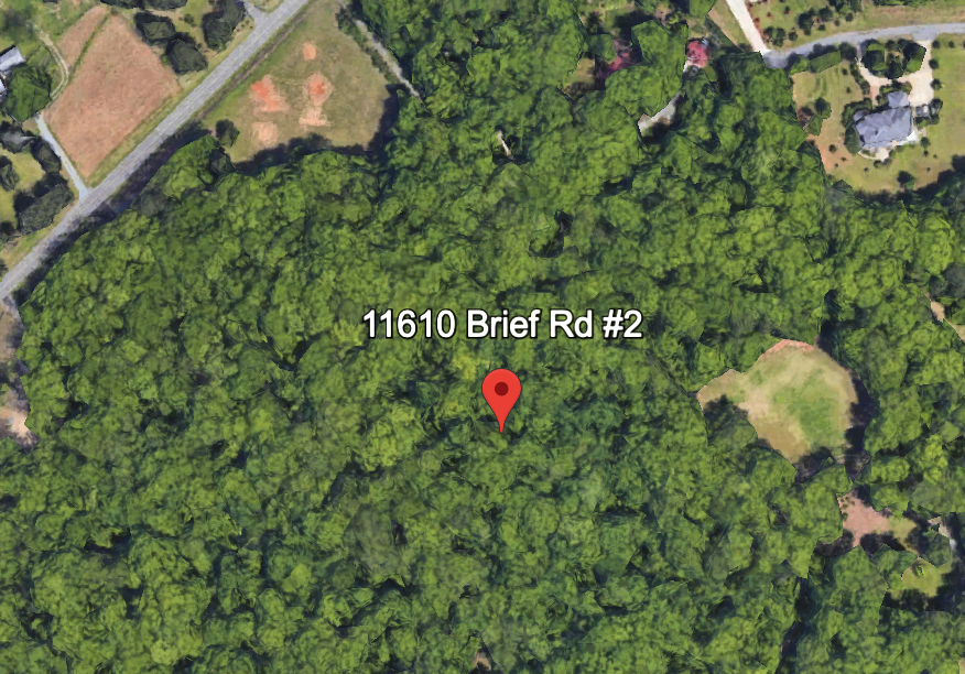
Source: Google Earth
Now, addressing the economic needs related to the land, the location offers significant advantages for homeless individuals seeking stability and employment. The plot is conveniently close to major transportation routes, including Interstate 485 and Interstate 77, which provide easy access to surrounding areas and key job centers. Uptown Charlotte, a major employment hub, is just a 30-minute commute away, making it feasible for residents to secure and maintain stable jobs. This accessibility to public transportation and major highways not only enhances mobility but also opens up a wider range of employment opportunities, which is essential for helping homeless individuals transition into self-sufficiency. By situating housing near these transport links, the community supports residents in overcoming barriers to employment, fostering economic resilience, and long-term stability.

Source: Google Earth
Testing Location
Testing Location
When testing for sand in Senegal, I needed a site with naturally exposed sand. I identified a spot that my parents and I often visit during our hikes and walks. This area has large sections of open sand, making it an ideal and easily accessible location for gathering samples and conducting tests.

While finding clay in Charlotte might seem easy, locating an area where the clay is already exposed is actually more difficult. Most of the ground is covered by topsoil, grass, or other surface materials. If found an area that was near the sandy section of the four-mile creek that had clay with sand on top.
Testing
At the first testing location, we encountered a sandy slope that closely resembled the natural terrain found in many parts of Senegal. To prepare the site, we used a piece of cardboard to level the surface, flattening the loose sand as much as possible to simulate a stable building ground. Once the surface was prepared, we carefully placed the house model on top and performed a basic stability test by gently shaking the ground around it. To our satisfaction, the model remained firmly in place, showing no signs of tipping or sliding — an encouraging sign for how it might perform on similar terrain in real-world conditions.

In addition to the successful test, the location itself provided a beautiful setting. A nearby stream added to the natural landscape, allowing us to capture a number of scenic photos that not only documented the process but also highlighted the kind of environment this structure is meant to withstand. The experience helped us better understand how natural terrain affects foundation stability and gave us valuable insight.

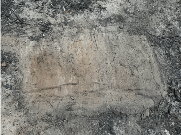
At the second test site, we discovered a sandy area that at first felt soft but had a hard base. By digging in a bit, we encountered a compacted clay layer, which was the same as the dense, clay-type soil that is common in Charlotte. This rendered this area ideal for replicating how the foundation would engage with common Charlotte soil.

We placed the model house on top of this composite surface and applied downward pressure to mimic the weight of an actual building. Not unexpectedly, the foundation settled into the sandy layer until it hit the clay below, where it was solid. Then we performed another round of shaking and motion tests around the perimeter. The model was stable and firmly in place, with no sign of shifting or tilting.

This experiment confirmed the effectiveness of the foundation design, which can yield and set down solidly even on uneven terrain with mixed soil. It also distinguished the manner in which layered soil structure — e.g., sand over clay — has a tendency to self-stabilize light modular structures naturally.

Reflection
I have always served in my church since I was young, and through that involvement, I began volunteering at Roof Above in Charlotte, NC, where we serve breakfast to an average of 150 homeless individuals each week. Some guests come with their children, and seeing that has deeply moved me. I often ask myself, why can’t the county provide more housing for those in need? That's the question that sparked the idea for Project Senegal - a vision where homeless and low-income individuals can one day afford a home of their own.
This dream was further shaped by a mission trip to Senegal, West Africa, where I had the opportunity to connect with street boys and orphans who struggle daily to find shelter, and their next meal. Though they had very little, they carried a deep sense of joy and resilience that inspired me. It made me realize the importance of creating opportunities for future generations to achieve housing stability, even with limited resources. I hope this project will one day become a reality for affordable housing. I've also gained some key skills while working on this project:
First-Hand Experience with Fusion 360
Before beginning this project, I had no experience with Fusion 360. This journey gave me valuable, hands-on exposure to CAD modeling, enabling me to turn my ideas into tangible, mechanical prototypes. I'm incredibly thankful to Autodesk and Instructables for offering a platform that cultivates intellectual curiosity and empowers students like me to think creatively and build with purpose.
Growth Through Rendering Studio
One of the most rewarding parts of the project was working with Rendering Studio. The software ignited my creativity, allowing me to produce photorealistic images from my 3D models—something I never imagined I could do. More than that, it helped me strengthen my presentation and communication skills, areas I’ve always struggled with. I now feel much more confident in sharing my work and collaborating with fellow designers.
Key Lessons Learned
Throughout this experience, I’ve learned that planning and time management are critical when balancing different parts of a complex project. From sketching and CAD modeling to rendering and prototyping, staying organized helped me stay on track and bring my vision to life.
Acknowlegdments
I would like to sincerely thank the following people who supported me throughout this journey:
Thank you to my parents for being an incredible support system—driving me to places, encouraging me, and caring for me through many long nights.
Thank you to my uncle, a materials scientist at Micron, for guiding me through material selection and helping me rethink critical aspects of my design.
Thank you to Ajith or AJ for mentoring me throughout the submission process and helping me navigate the details with clarity and confidence in Instructables.
Thank you to Calvary Church for providing me the opportunity to travel to Senegal—an experience that truly changed my perspective and inspired this entire project.
And utmost thanks to the Autodesk team for making your products available to students, and I will for sure be using Fusion 360 to design our FTC team's Robot next Season.
I hope you all learned something from this project, and I will do my best to respond to any questions that might arise.