Prototype Suitcase
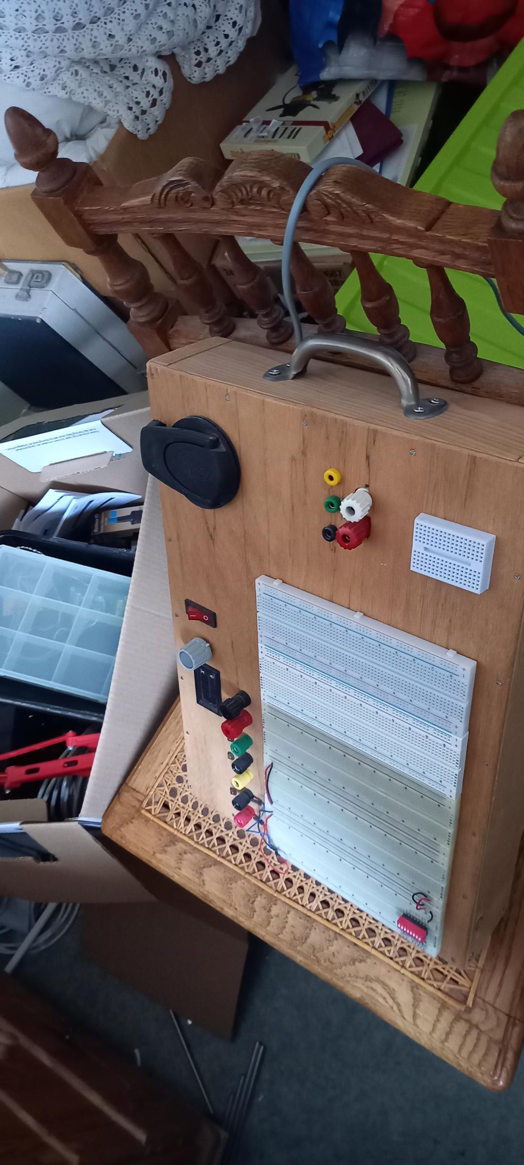
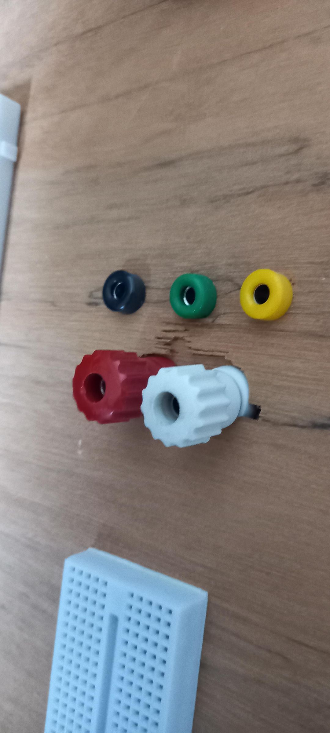
A looooong time ago, I built a prototype suitcase — basically a wooden box with a portable power supply inside and breadboards mounted on top. Plus a handful of other fun little gimmicks. I had a great time with it, and it served me well.
Until the day I dropped it 🫣. The sound it made when it hit the floor… let’s just say it didn’t promise anything good. When I opened it, everything inside had snapped loose, and the outside had a few cracks too. So I stripped it completely and decided to start fresh.
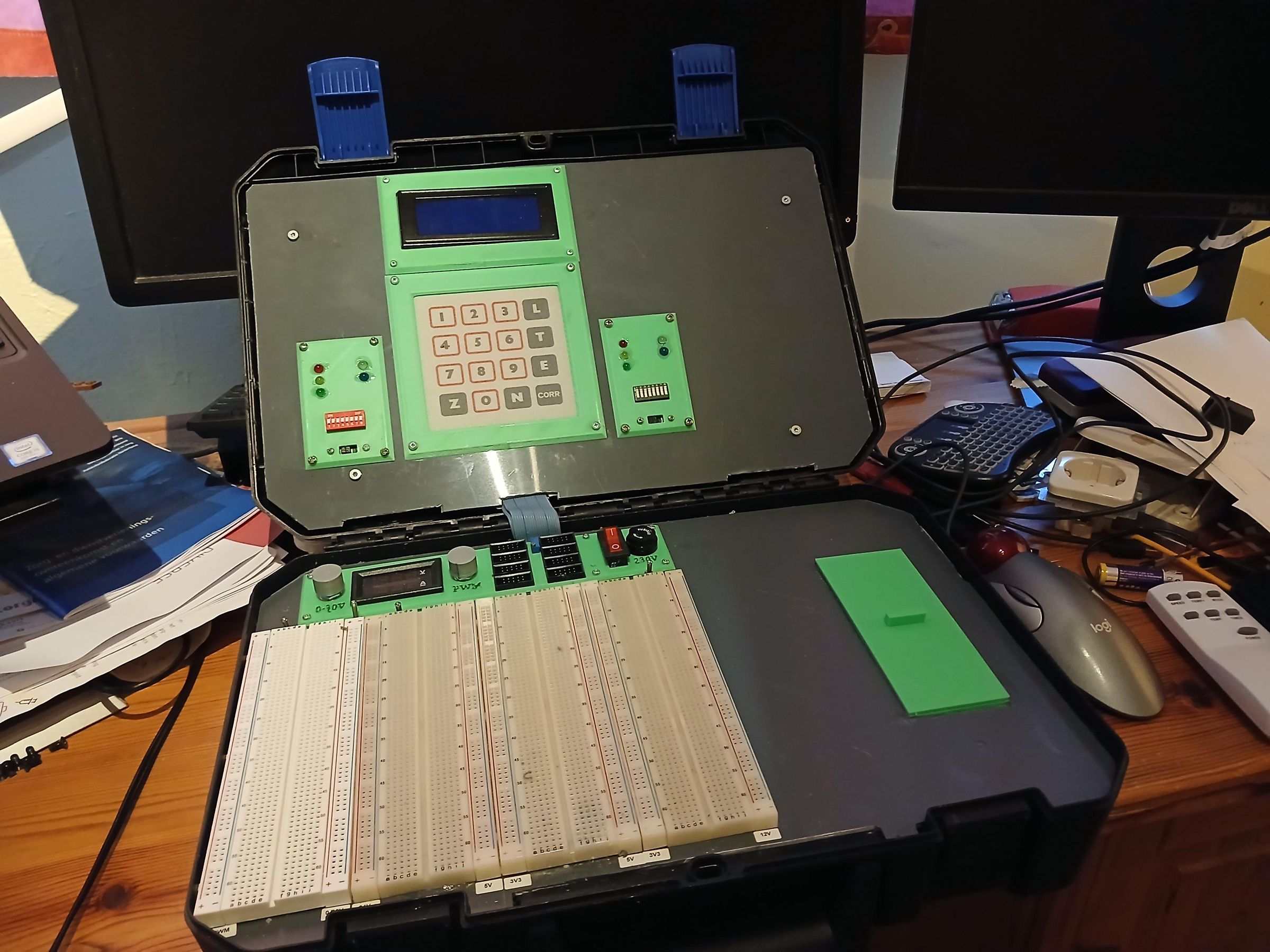
I had an old Dremel suitcase lying around — one that was basically waiting to be thrown out — and I thought: “Well… why not use this instead?” And so the Dremel prototype suitcase was born!
Supplies
From the broken prototype Suitcase I reused the following:
- 1pc VDC/ADC measuring display
- 1pc main switch with light
- 4pc breadboards
- 1pc dip-switch (8-fold)
- 1pc diode bridge type RS402
The rest I stored for later use
From my own stock:
- 1pc safety transformer 230/15V 100Va
- 1pc safety transformer 230/24V 80Va
- several JST-XH 2/3/4 Pins & Connectors
- 4pc change-over toggle switch
- 5pc 3mm LED orange with a flat head
- 1pc potentiometer 10k with knob
- 1pc potentiometer 500k with knob
- several electronic components (see schematic later on)
- 1pc 230V 2pole connector Euro type c8
- 1pc power cord Euro type C
- 1pc Dremel suitcase
- several types of circuit boards
- PVC plate 3mm thick
- 1pc dip-switch (8-fold)
- 2pc 5mm LED red
- 2pc 5mm LED yellow
- 2pc 5mm LED Green
- 2pc 5mm LED white
- 2pc 5mm LED blue
- 1pc 16x4 character LCD display
- 1pc 4x4 foil keyboard
- PLA 1,75mm wire
Used tools:
- chisel
- side & head wire cutter
- box cutter
- file
- soldering iron
- crimp tool for JST-XH connectors
- 3D printer
- jig saw
- Patience (lots off it)
Prepare the Dremel Suitcase
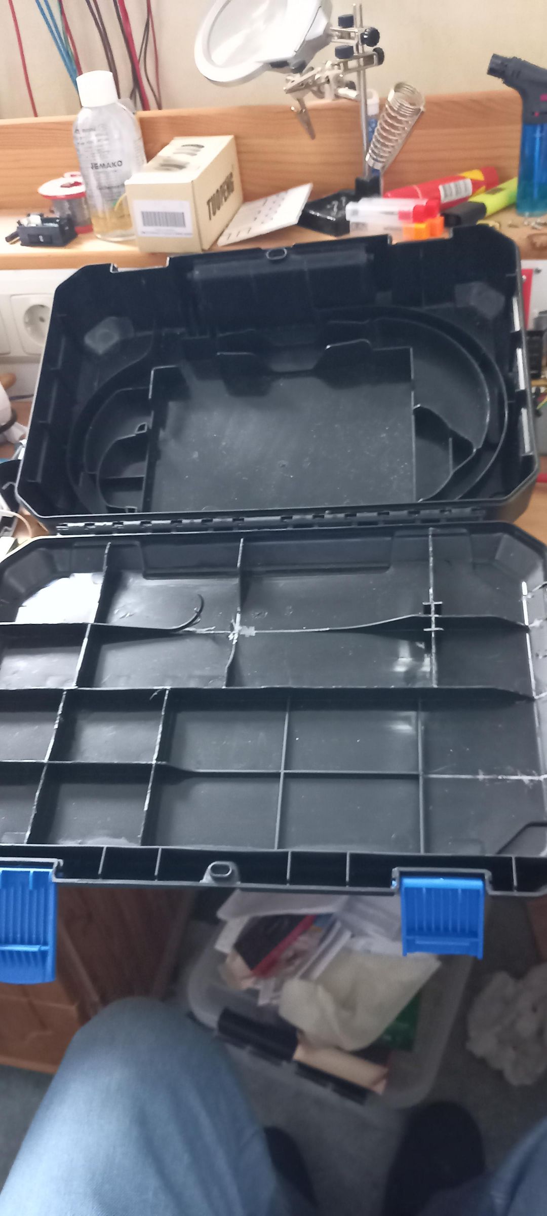
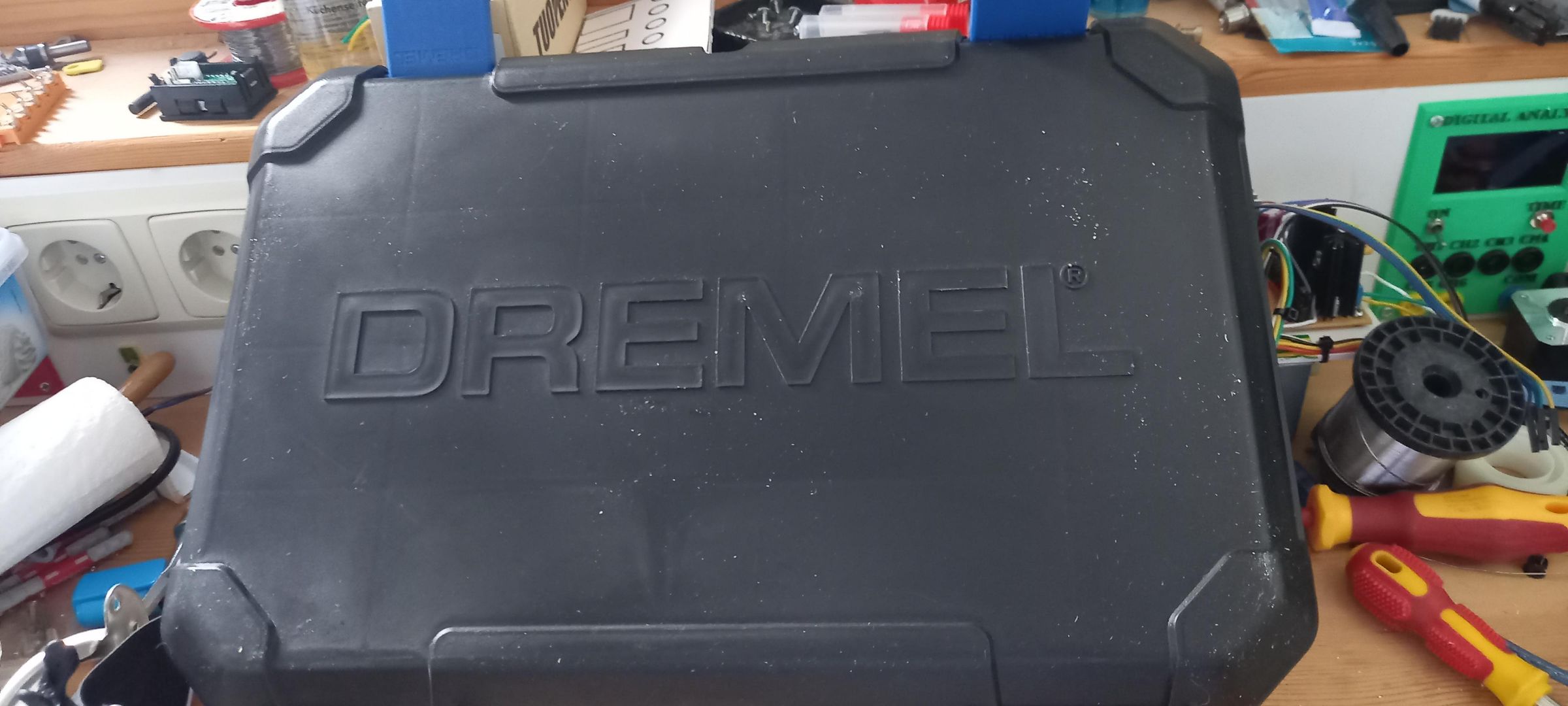
The Dremel suitcase originally had a lot of special supports inside — all shaped to hold the Dremel tools. Those needed to be removed to make space for the new build. I took out everything from the bottom except the side supports, and everything from the lid except the reinforcements near the closing latches.
To remove the supports, I used both a head wire cutter and a side wire cutter. After cutting them out, I smoothed the remaining stubs with a chisel. It sounds simple, but it took quite a bit of time to get everything clean and flat.
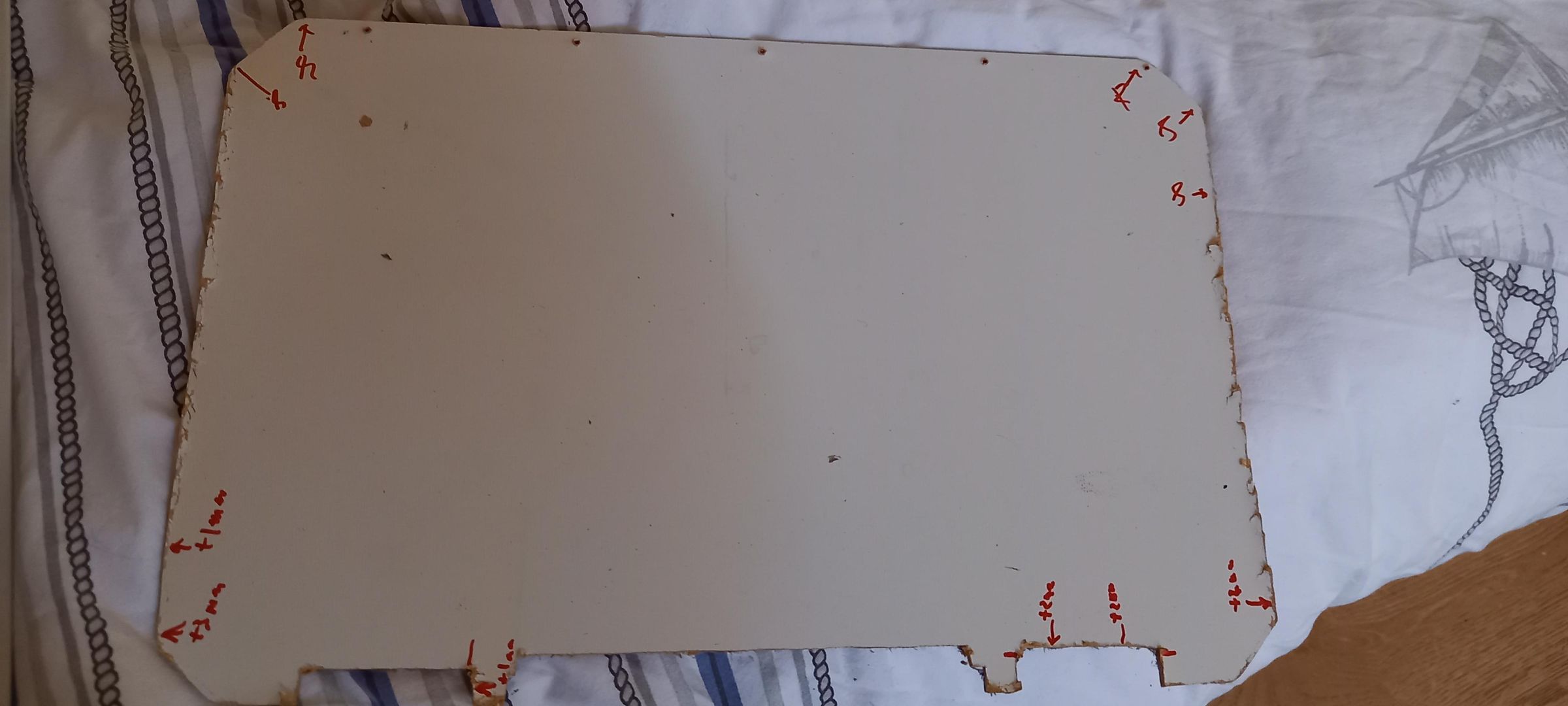
The old bottom plate from my previous prototype suitcase became my sawing template. It was a 2 mm sheet of compressed wood pulp. I carefully trimmed it to fit inside the new suitcase, marking the sides and corners to note where it fit perfectly — and where I had accidentally cut off a bit too much.
I transferred the template onto a PVC plate and cut it out with a jigsaw. To make it fit purrfectly (yes,I am still a cat person 😸), it only needed some filing along a few edges. I repeated the same process for the lid, but I forgot to take a picture of that part.
The Breadboards
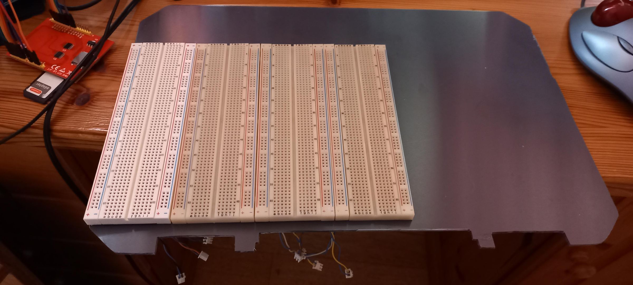
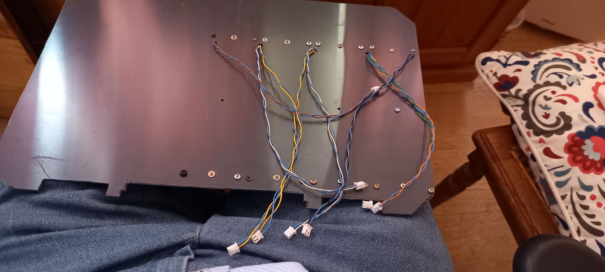
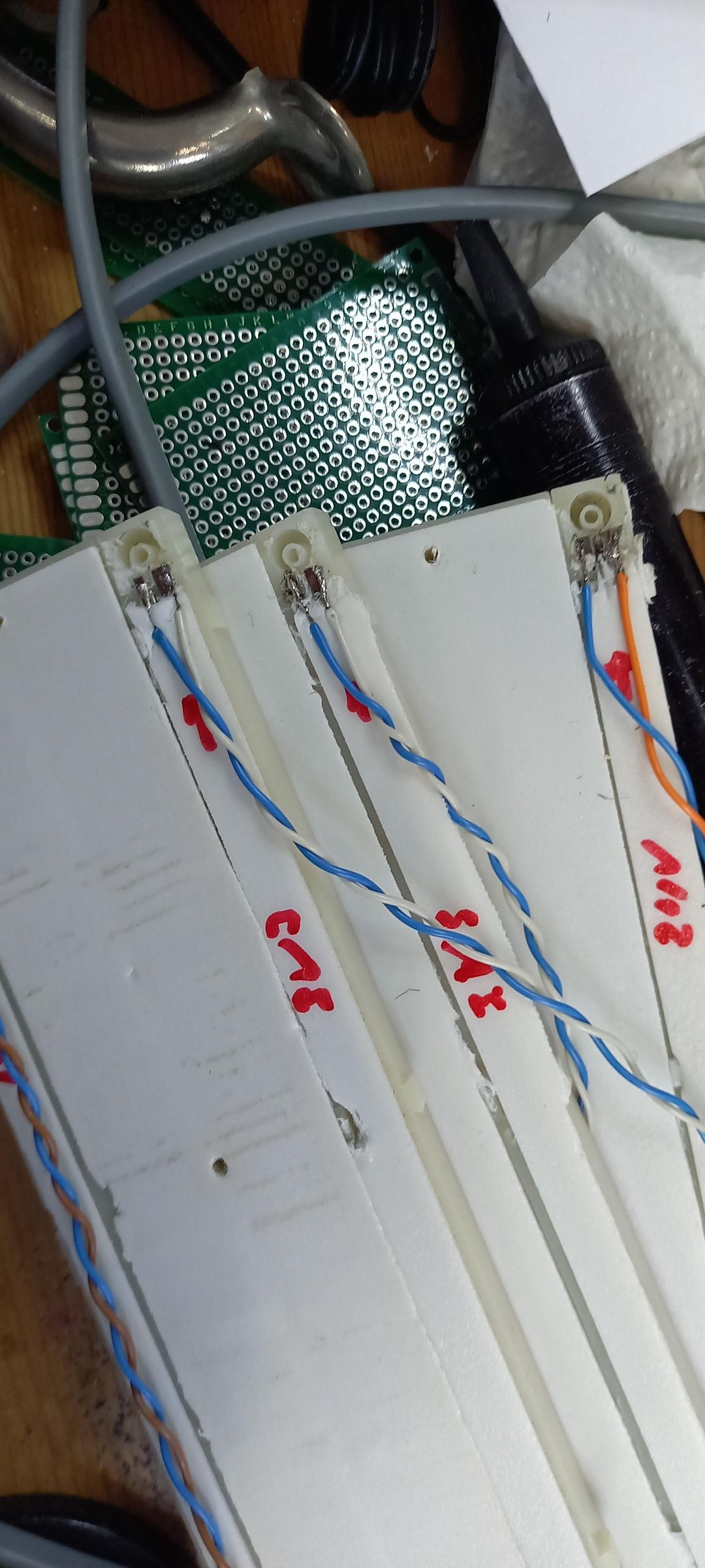
To optimize the supply connection I had the idea to connect the supplies directly to the supply part of the breadboards.
I wanted the most used supplies:
- 2x 3,3V
- 2x 5V
- 1x 12V
- 1x 24V
and for signal use:
- 1x 0-30V
- 1x PWM
It turned out that the bars inside the breadboard are made of stainless steel, at least the types that I had.
That's quite hard to solder! But I got it done.
I had two Different types of breadboards.
It turned out that the mounting holes were on different places for each brand, so I had to make a custom drilling plan. But at the end they were tightly placed on the PVC plate.
If you make this, check your mounting holes. Different brands have different drill patterns!
Supply Print
Safety first
Before I start talking about the PCB, let’s talk safety first!
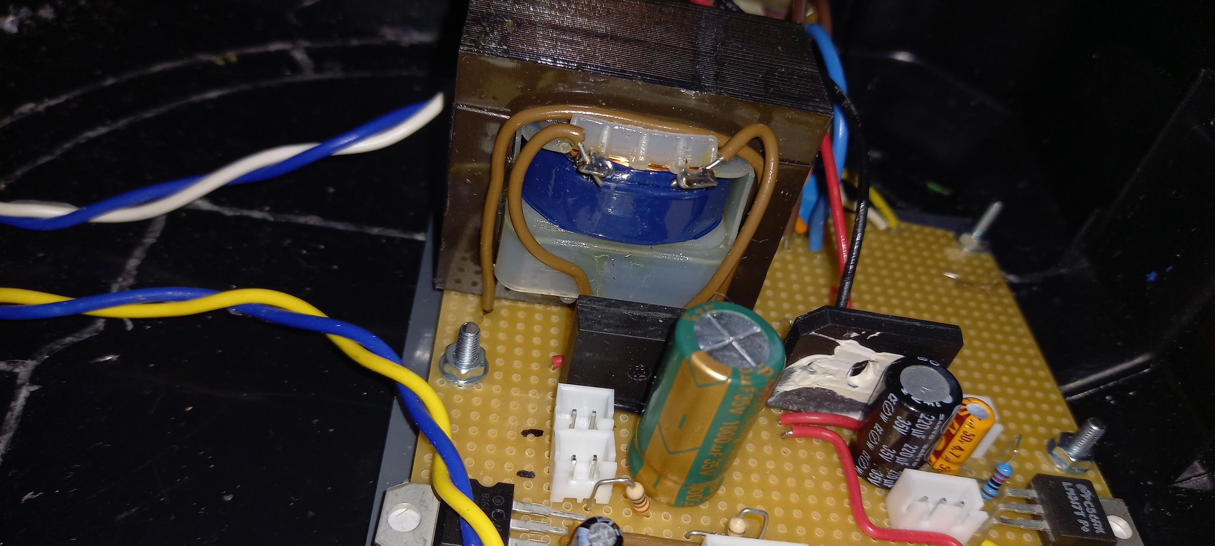
I use safety transformers, which are different from normal transformers. In a standard transformer, the primary and secondary windings are stacked on top of each other with only a foil insulation between them. If one winding fails, it can damage the other — and there is a real risk that line voltage may pass to the secondary side.
With small transformers this risk is even greater due to lower insulation class and higher overheating potential.
Safety transformers, however, have completely separated windings with high‑grade insulation between them and the core. If one winding fails, the other remains unaffected. This means the secondary side stays safely isolated from line voltage at all times.
The PCB
I separated the supplies into two circuits:
- The common 5 V, 3.3 V, and PWM (5 V) run on the 15 V secondary transformer.
- The other supplies run on the 30 V secondary transformer.
The bridge rectifiers are oversized, but that’s simply what I had available. Each circuit has a buffer capacitor, and I chose to use a common neutral.
Most circuits I build are digital, so the 5 V and 3.3 V rails are used most often. The other supplies are used less frequently, so I made them switchable.
For the 5 V, 12 V, and 24 V rails I used the L78xx series, each with a 10 nF ceramic capacitor for noise reduction and a 4.7 µF buffer capacitor.
For the 3.3 V supply I hesitated between using an SMD regulator or a LM317. Since I have no experience with SMD, I chose the LM317 with a resistor network set to 3.37 V, again with 10 nF and 4.7 µF capacitors.
The 0–30 V supply is a standard LM317 circuit with a 10 k potentiometer.
PWM circuit
The PWM circuit is built around a NE555 and a 500 k potentiometer, powered from the 5 V rail. I boosted the NE555 output with a transistor to get a bit more power. I also wasn’t sure whether I might need a higher‑voltage PWM in the future, so I reserved space on the PCB to modify this later. The transistor can switch up to 24 V, which is a nice bonus.
Each circuit has a 3 mm orange LED as an indicator.
I mounted the PCB on a separate PVC plate and glued it into the bottom of the suitcase.
Power ,Switches, Indicators and Connectors


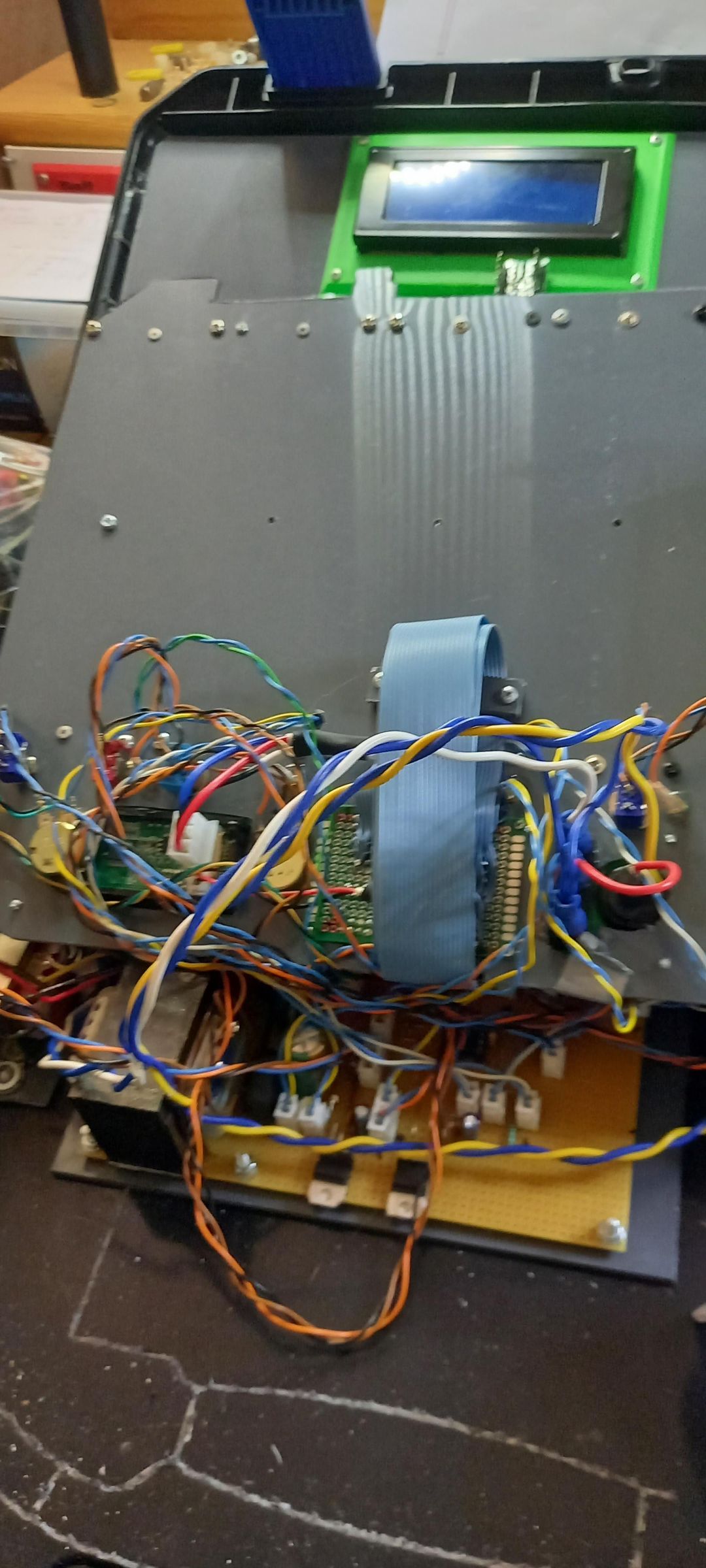
I started with the switches for the 12 V, 24 V, 0–30 V and PWM, along with all the LED indicators from the control PCB. I first tried making a cover with all the required text, but it looked awful, so I decided to mount everything directly into the PVC plate. I glued the indicator LEDs in place using UV resin.
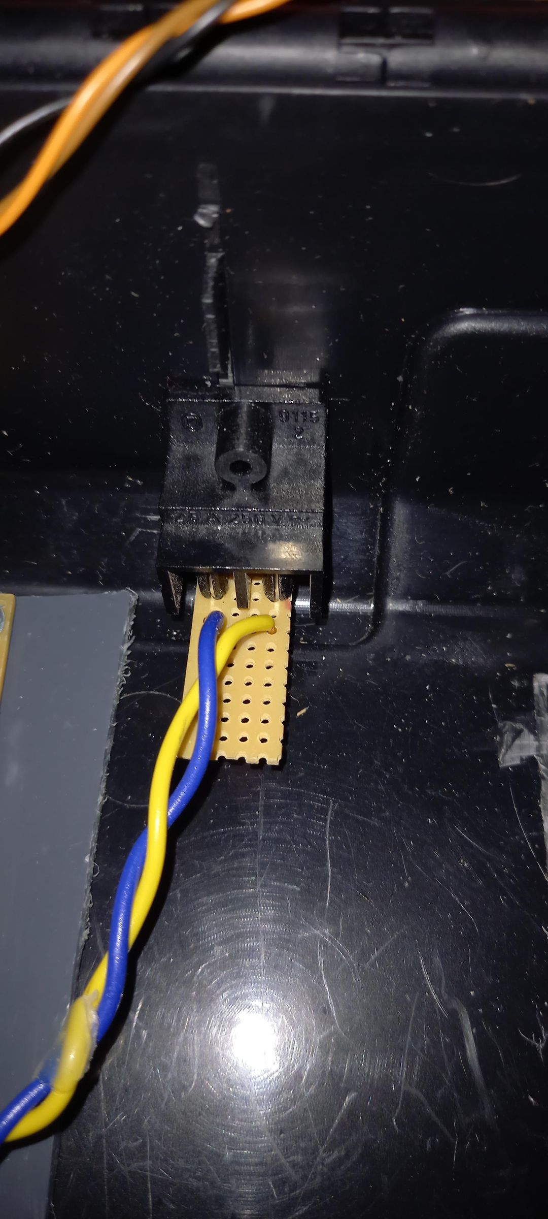
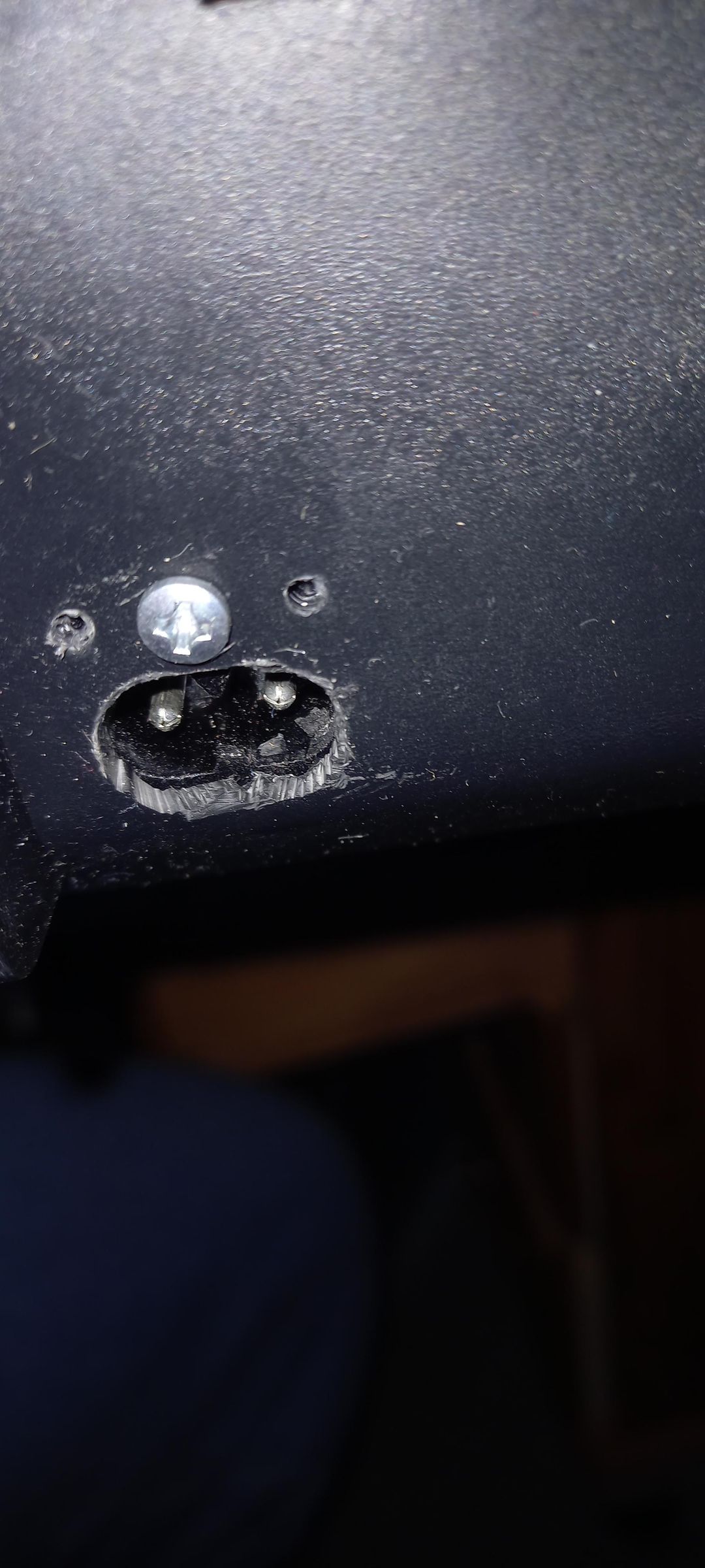
The C8 power connector was installed at the back of the suitcase. It is mounted with a single screw and has two retaining pins beside the screw hole. The screw is fully isolated from anything inside, so there is no safety risk.
Next, I made a plate for the potentiometers, the V&A meter, the connectors, and the power switch with fuse. I cut out the holes, mounted all components, and attached the plate to the PVC base.
After that, I wired everything using the correct connectors.
I also added eight 10‑pin male connectors: six for items that will be mounted in the lid’s PVC plate, and two spares for future expansions. I used ribbon cable to connect them — a very patience‑testing task.
Once everything was hooked up to the PCB and the power connector, I realized I had made a mistake 🫣 There wasn’t enough clearance between the signal switches and one of the transformers on the PCB.
Fortunately, I could remove the transformer and place it next to the PCB. I also made a small container for breadboard wires and connectors and mounted it in the PVC plate.
With that, the bottom section is finished!
The Lid
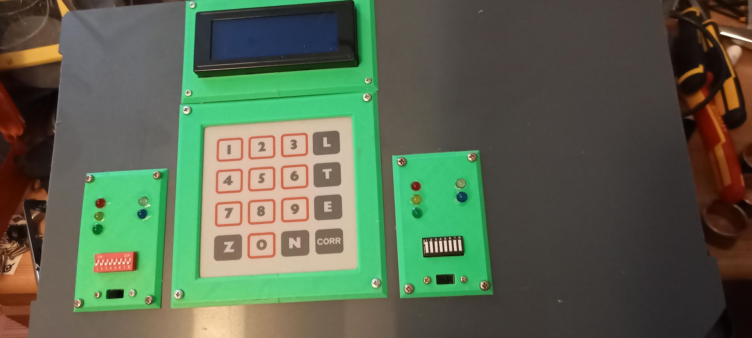
I wanted some switches and LED's in the lid for HMI. I also had lying around for ages a 4x4 foil keyboard and from an old 3D printer a 16x4 character LCD display, I decided to incorporate that to.
With Tinkercad, I designed some frames and plates for the items. Two plates for 5x LED's, dip-switch and a double pole change-over switch.
The LED-print and display had some irregular shapes, so cutting holes for it proved to be challenging, but I got them reasonably aligned.
It proved to be very challenging to solder those wires, it took me a long time to do so.
I added some supports with threaded inserts (M3) and glued them on the bottom (after I Aligned them up with the screws).
When I closed the lid for the first time I realized that the knobs for the Potentiometers were too high, and I clamped the display between the lid and the decorative frame. It was too high to. So I made new knobs with my 3D printer and put the display behind the lid, problem solved.
I wanted some switches and LEDs in the lid for HMI. I also had a 4×4 foil keyboard lying around for ages, and a 16×4 character LCD display from an old 3D printer. I decided to incorporate both.
Using Tinkercad, I designed frames and plates for the components: two plates for 5 LEDs each, a dip switch, and a double‑pole change‑over switch.
The LED PCB and the display had irregular shapes, so cutting the openings for them was quite challenging, but I managed to get everything reasonably aligned.
Soldering all the wires proved to be very time‑consuming — it took me quite a while to get it all done.
I added supports with threaded M3 inserts and glued them to the underside of the lid (after aligning them with the screw positions).
Final Toughts
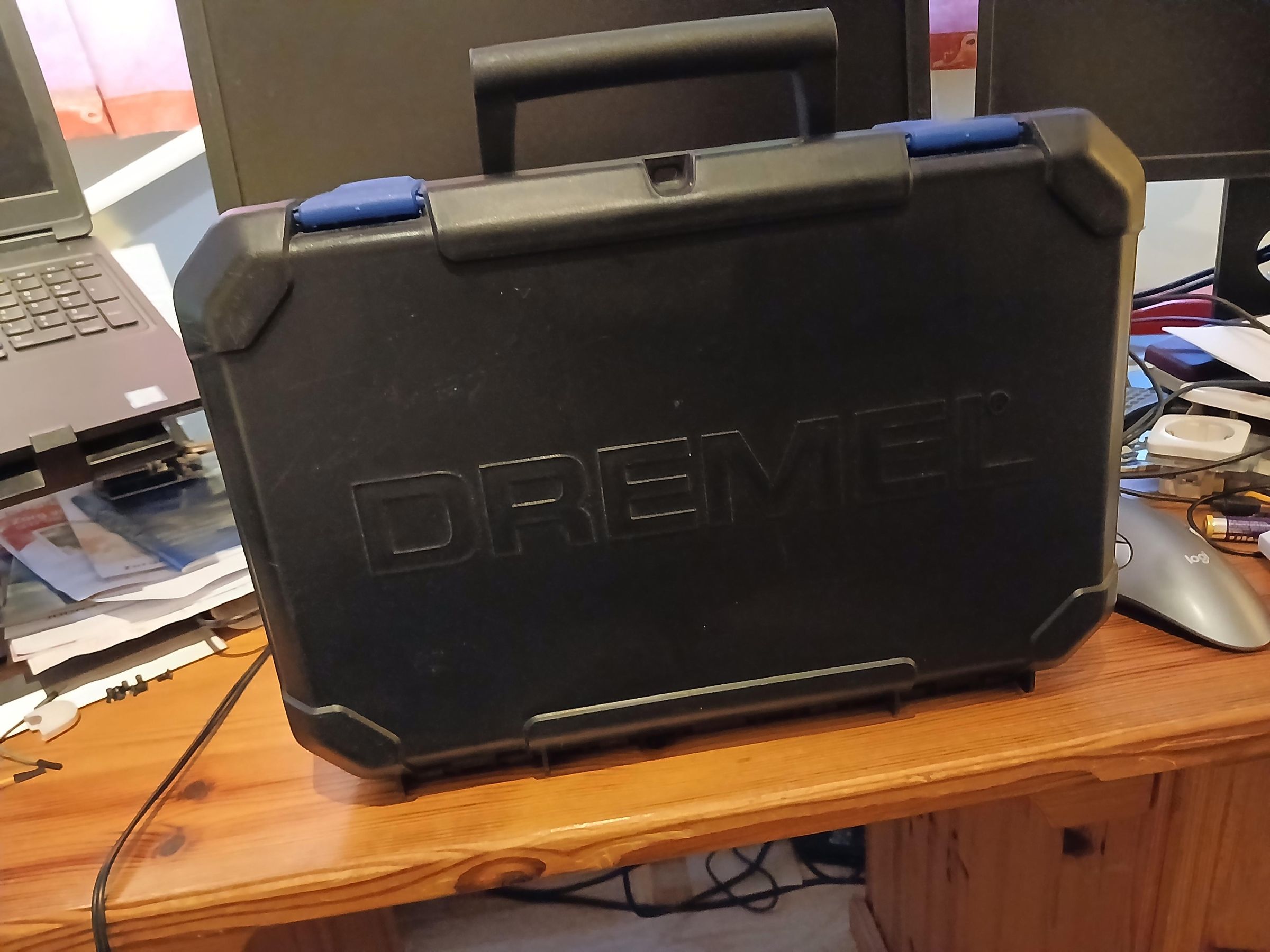
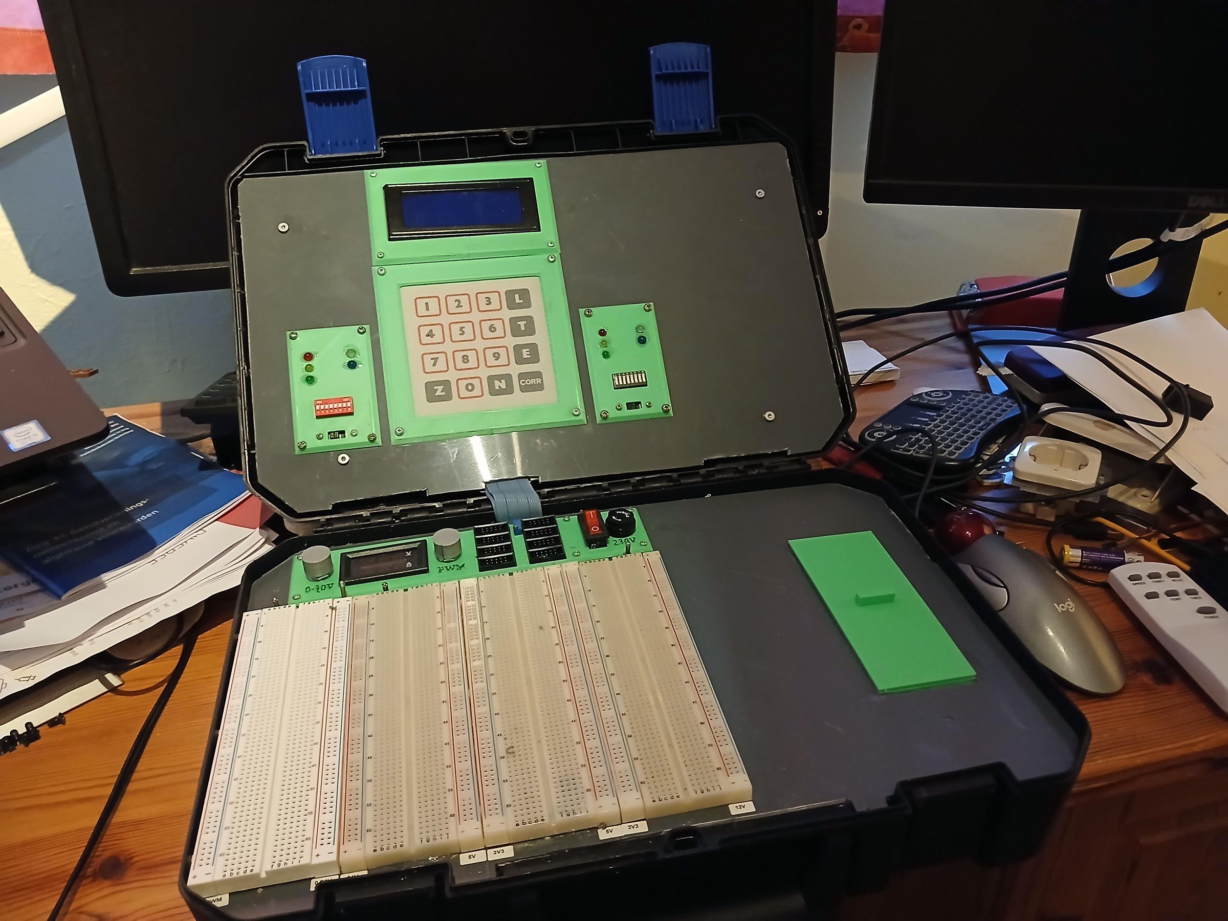
This project really challenged me, but I’m glad I was able to re‑use so many old materials. There’s still room for future expansions if I ever need them.
I’m genuinely happy with the end result, and I hope I’ll have just as much fun with this suitcase as I had with the old one.