Prototyping a Guitar Effects Pedal Using 1940s Design Conventions
by Gabriel Mejia-Estrella in Circuits > Audio
8057 Views, 58 Favorites, 0 Comments
Prototyping a Guitar Effects Pedal Using 1940s Design Conventions


This project was generously sponsored by NextPCB, whose PCB Manufacturing services allowed me to take this idea from schematics to reality. NextPCB provides accessible, high-quality circuit board manufacturing and assembly, making it easy for independent builders to prototype, iterate, and share their work with the world. Click here to get a quote today.
Lately, I've been obsessed with the idea of building musical gadgets that have a highly specific aesthetic. This project is no exception: a fuzz pedal in the rugged industrial style of the WWII era.
Why WWII?
Well, it occurred to me that there's a big overlap between the design principles used in WWII military equipment and what guitarists value in a guitar pedal. Guitarists love analogue electronics, rugged design, and vintage aesthetics, and WWII military standards hit those rivets on the head.
This Instructable is a bit technical, yet somehow there are still parts I feel I could have gone in more depth. In an attempt to remedy this problem, I’ve included links throughout the Instructable to further reading, and you’ll also find a list of helpful resources in the last step.
But anyway, let's start with the basics: what is fuzz?
Fuzz: a Brief History
Fuzz as a guitar effect was born in the 1960s at the intersection of technology and culture.
In the 1950s, guitarists had been experimenting with ways to shape the sound of the electric guitar. Link Wray, for example, famously punctured holes in his amplifier speaker to get the distinctive guitar tone on the 1958 track "Rumble.” Despite being an instrumental track, the song was banned from many U.S. radio stations for its aggressive sound and association with juvenile delinquency.
A few years later in 1961, what we now recognize as the first fuzz effect happened during the recording of Marty Robbins’ "Don't Worry.” A transformer either in the recording console or an amplifier malfunctioned, tearing the bass guitar signal into a distorted growl. The song was released with a distorted bass solo and became a number one hit on the country charts.
Seeing the potential of this new sound, the audio engineer behind the session, Glen Snoddy, teamed up with his colleague Revis Hobbs to create a guitar pedal that could produce this distorted sound on demand. They sold the circuit to Gibson and the pedal was released as the Gibson Maestro FZ-1 Fuzz-Tone in 1962.
 Initially, the pedal was a commercial flop, with only a couple of units being sold in the first few years.
Part of the problem was that there was a cultural mismatch between the sound that the pedal represented and the way it was marketed. This new sound was gritty and rebellious and had the potential to capture the spirit of the counterculture movement, but the conservative advertisements of the 1960s painted the pedal as a way to reproduce brass sounds with your guitar.

Fortunately, this kind of marketing did appeal to one guitarist: Keith Richards of the Rolling Stones, who used it on the hit song "I Can’t Get No (Satisfaction)" (1965).
Here I’ll take advantage of the fact that I’m in a Barnes and Noble to look for Richard’s autobiography, where he writes, "In Satisfaction I was imagining horns, trying to imitate their sound to put on the track later when we recorded...But we didn't have horns, and I was only going to lay down a dub. The fuzz tone came in handy so I could give a shape to what the horns were supposed to do. But the Fuzz tone had never been heard before, and that's the sound that captured everybody's imagination."
”Satisfaction” became a number one hit and cemented the fuzz pedal’s place in rock ‘n’ roll history. Soon everyone from Jimi Hendrix to Eric Clapton was using the effect.
In this Instructable, I’ll be showing you how to create a similar effect with a handful of electronics components and a simple circuit.
Materials, Tools, and Files
Here's everything you'll need to build this pedal:
Tools
- Breadboard
- Wire strippers
- Multimeter
- Soldering iron and solder
- CNC Machine
- Woodworking clamps
- Drill Press and 90 degree countersink bit
- Silkscreening kit
- Inkjet Printer
- UV Light source
Materials
Electronics:
- 9 volt battery or power supply
- 1/4" audio jacks
- LEDs (these 5mm LEDs work but are a bit small, you may want to try 10mm LEDs)
- LED mounting bezel
- DC power jack
- Wires
- Mounting screws
- 3PDT footswitch
- Electronics Kit (resistors, capacitors, and transistors)
- Potentiometer kit
- Copper Tape
Enclosure:
- Pine Board (I'd recommend planing the board yourself to get it to an even 1/4" before machining)
- Titebond III Wood glue
- Brass Screws
- Olive Drab Paint
- Photo emulsion
- Screen Printing Ink
Files
Downloads
Prototyping: Basic Fuzz
If you want the finished schematic that I created, you can skip to step three, but I figured I’d lay out for the multiple attempts it took me to get to the finished result. Circuits don’t always behave in the real world the way they do in theory, so expect some trial and error at this stage!
Having some basic knowledge about electronics will make your life easier though. I found this resource to be helpful for learning about breadboards, which we'll use to prototype the circuit. This Instructable by Randofo is super helpful as a primer (or refresher!) of how electricity and different electrical components work. Lastly, here’s an article that teaches you how to read a schematic, which we’ll need as we will be working with a couple of schematics I found online.
We'll start off using this simple schematic from Beavis Audio:
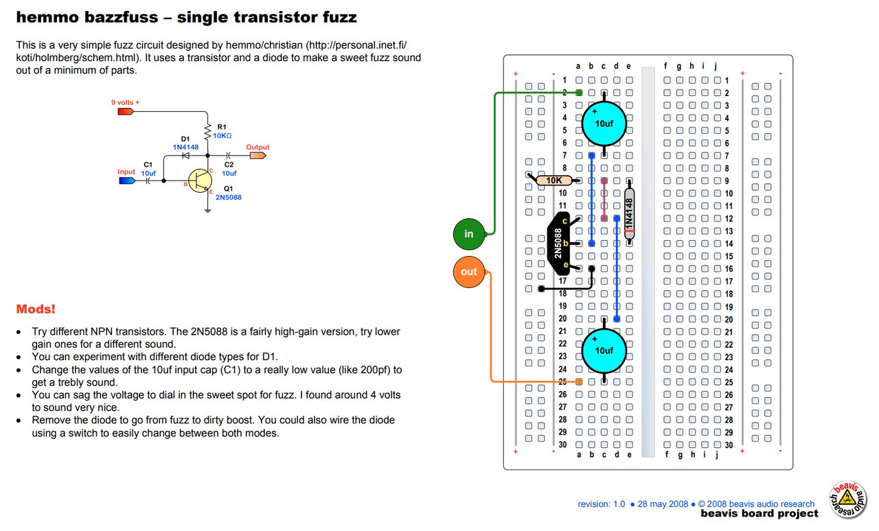 This circuit is great because it's as basic as it gets: just two capacitors, a diode, one transistor and one resistor make up the circuit.
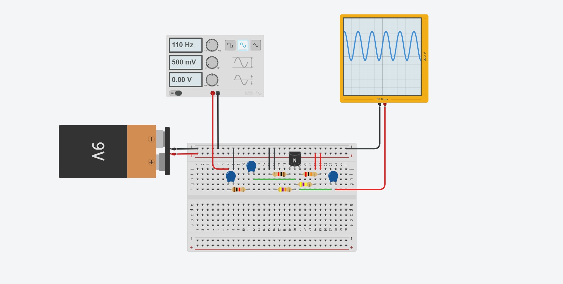
Interactive Simulation:
Electronics can can a little abstract, so to make things easier to visualize I took the schematic above and created a virtual simulation in TinkerCAD. The cool thing about this simulation is that you can see how the circuit affects the incoming signal. The input is a sine wave generator, and the oscilloscope shows you the outgoing signal. You can see in the photo below that the circuit takes our pure sine wave and outputs something more like a square wave.
Click on the photo below to try tweaking different component values, taking out components and adding new ones to see how it affects the incoming signal.

Signal Flow:
I also made a second simulation, and this one shows you exactly how the current flows through the circuit. I’m no electrical engineer, but here’s my understanding of how the circuit works:

Battery:
- The 9 volt battery powers the circuit. The transistor in particular is an active component that requires battery power to work properly.
Transistor:
- The transistor increases the amplitude of the guitar signal. It has three terminals: an Emitter, Base and Collector. Direct current from the battery flows from the collector to the emitter. The guitar signal is applied between the base and emitter.
Resistor:
- The one resistor in the circuit regulates the voltage at the collector of the transistor. If you use too high a resistor value the output of the circuit will be quiet and sputtery. Too low a resistor value leads high gain and noise.
Diode:
- Diode feeds part of the collector signal back to the base, causing nonlinear clipping.
Capacitors:
- The two 10 nF capacitors in the circuit block direct current while allowing the audio signal to pass. If the DC from the battery were to escape to the guitar or the speakers, it would introduce unwanted noise. Each capacitor forms a high-pass filter with the surrounding circuit, so changing the capacitor values can subtly shape the sound of the guitar.
Now to actually put it together on the breadboard! I used mini breadboards in vain thinking that they would fit in the pedal enclosure. They don’t, and they’re a pain to prototype with. But here is what the physical, breadboarded circuit looks like:

How It Sounds (LOWER YOUR VOLUME!! IT’S LOUD!!)

Okay, now to test the circuit!
In the video above, I recorded a short guitar riff then ran the same riff back through my makeshift fuzz circuit. The video shows you a spectrogram, or a visual representation, of the plain guitar signal and fuzzed guitar signal side-by-side. The vertical axis shows you what frequencies are present in the audio (low frequencies at the bottom, higher frequencies on top), and the color shows you how loud those frequencies are, with yellow representing the loudest frequencies.
Comparing them, we can see that the fuzzed guitar signal has added overtones not present in the original audio. These overtones are the result of the circuit hard-clipping our audio signal.
There are a few things that could be improved here. You can hear an insane amount of noise in the background that sounds like static. That’s something to work on.
Something that isn’t super apparent in the video is that this circuit tends to “gate”, or cut out abruptly, especially when your guitar is set to a low volume or when you play higher-pitched notes. This circuit was originally intended to be used for a bass guitar, after all. We’ll fix both these problems in the next step.
But, there’s also a lot of potential here! I like how gritty it sounds. Very 60s counterculture.
And if you wanted to, you could leave the circuit at this! Part of the charm of building your own circuit is that it's imperfect. There's noise, it cuts in and out, and you made it.
Prototype 2: Adding a Preamp
As I was researching different Fuzz circuits, I realized that the gating I was hearing was probably a limitation of using just one transistor. The Maestro FZ-1 and the Dallas Fuzzface both use multiple transistors in their circuits.
So, I decided to see what would happen if I introduced another transistor into the circuit. This transistor will serve as a clean preamp, raising the amplitude of the clean guitar signal before feeding it into the Fuzz circuit. This magical single transistor preamp looks like this:
This is an example of a Class A amplifier. It relies on one transistor to amplify the incoming audio signal, and the four resistors surrounding it carefully regulate the voltage level across the transistor.
On its own, this circuit simply raises the volume of an incoming signal. This is exactly what we need to fix the gating. What I did was mash these two circuits together (the preamp and the fuzz circuit) to create the final schematic I used in the project:

A couple additional things: in my trial and error, I found that adding a resistor in series with the guitar input (R5) significantly reduced unwanted noise. Same with adding a capacitor from input to ground (C6).
I also added a series resistor in between the two circuits (R7), again to help reduce noise. The values of some components (R8, for example) also had to change once I mashed the circuits together. This was mostly a matter of swapping out different component values to find out what sounded best.
Lasty, the schematic shows an LED connected to ground via a resistor. This is a mistake! The LED should connect to +9 Volts. I haven't gotten around to fixing this in the board yet, so you may want to change it. If you order the board as-is it's not the end of the world; you'll just need to hand wire the LED to 9 volts.
A Word From Our Sponsors

I’d like to take a moment here, ladies and gentlemen, to tell you that that this project was generously sponsored by NextPCB, whose help made this marvel of modern electronics possible!
The fine folks at NextPCB are master craftsmen of the printed circuit board (PCB), with over 15 years of manufacturing experience under their belts. When you’re ready to bring your electronics projects to life, NextPCB stands at the ready! Dependable quality! Affordable prices! Incredible service!
Simply upload your Gerber files to their website, place your order, and sit back as your design springs to life in the hands of the finest electrical engineers on the planet. Step right up and take advantage of their special offer here — your circuits deserve nothing less than the best!
Designing the PCB
… And now for our regularly scheduled programming! I started off by drawing up the schematic from the previous step in EasyEDA, a free software for designing circuit boards. Once I drew the schematic, I used their convert-to-PCB feature to lay out the components in the PCB layout editor.
“Convert-to-PCB” doesn’t literally create a finished footprint for you though - the flow of the electronics, the board outline, mounting holes are left to you!
I measured the pedal enclosure that I had already started designing and drew a board outline that I knew would fit inside, in this case 36 x 36 mm. I then placed the components in a way that made sense to me. By convention, guitar pedals have the input jack on the right and the output jack to the left, so I kept that same right-to-left logic when it came to designing the circuit board.
Another important feature of the board is the ground plane, which is the rounded blue rectangle that sits below all the components, as seen in the photo below. This layer of copper means that components have a quick and easy return to ground, minimizing noise. It also acts as a shield against Radio Frequency interference. Here's what the finished footprint looks like in the software:

If you’d like to create this board as is, I’m attaching the Gerber files, the BOM, and the Pick and Place files in "Files" step. NextPCB makes it easy to just upload these files and place your order. When you upload your BOM to their website, their parts inventory will pop up and tell you if any parts are out of stock or need to be shipped in to their factory, with an estimated lead time. As of the time of this writing, all the parts in the BOM are in stock, but double check as these things are subject to change! If you need to swap out a components you can look at the parts library in Easy EDA and corroborate it with NextPCB’s parts inventory.
Here's what the finished board looks like:

Creating the Box
Now that we have the electronics on the way, it’s time to create the enclosure that will house the electronics. As mentioned before, I love the gritty, rugged industrial look of the WWII era, along with the good old-fashioned craftsmanship that went into products of that time period.
I started by digging into the woodworking techniques of the era and found this insanely cool Army technical manual from 1943. It covers a wide range of carpentry techniques that were popular in the 1940s, most of which you won’t need for this project. Regardless, it was an interesting read, and the sections on joints and nail use definitely provided some inspiration for the final design.
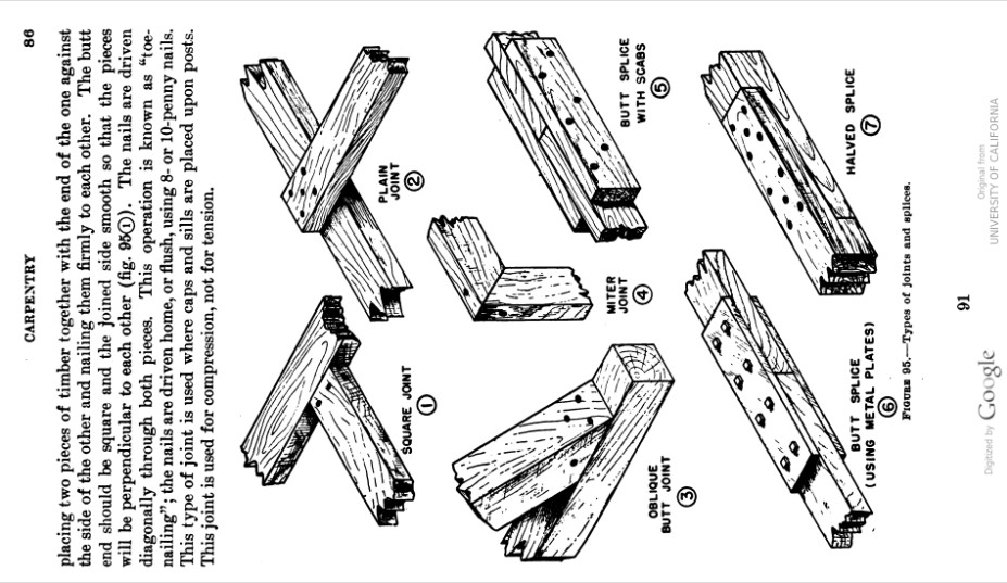
I also just looked around online at vintage products on Etsy. I loved the look of box joints that were popular back then, and definitely took some inspiration from the browning box, which was an ammo box used in WWI and WWII.

I’ll be using the CNC machine at my local MakerSpace to fabricate the pedal enclosure.
The software that my makerspace uses for the CNC machines is called Vcarve. It lets you create designs that you can then machine onto wood. You can tell the CNC machines to cut all the way through the wood, partially through the wood, you can swap out bits for different sections of a project, you can engrave complex designs, etc. here’s a quick and dirty Timelapse of the thing in action:

In this step I’ll be attaching the template for this bad boy. In the end I had to make some slight adjustments to the design. Namely, I had to adjust the tolerances a bit so all the electronics would fit comfortably. I basically had to hammer in the DC power jack to get it to fit in the enclosure.

Once it's been machined, we can assemble it into the box shape we all know and love:

I used Titebond III wood glue to make the joints permanent. You can see I’m not afraid to use clamps to hold the thing together while the glue dries:

Creating the Metal Panels
Similarly, we’ll need to fabricate the metal panels. If you want to replicate what I did, I’ve already drawn the panels and attached them for you to download.
I then exported my drawings as .DXF files and sent them to SendCutSend, a magical online service that lasercuts sheets of metal to your exact specifications. After the initial order, I made some small adjustments to the files. The screw holes and the hole for the LED mount were slightly undersized, so I increased their diameters for good hardware clearance. The files attached reflect these changes.
Here are the finished metal panels in all their beauty:

With the panels cut, the next step is preparing them for mounting to the box. We’ll be attaching these panels to the wood box using some brass screws, and in order for these screws to sit flush with the metal, we’ll need to carefully countersink each of the screw holes. I used a 90 degree countersink bit attached to a drill press and carefully plunged it into each hole.

Once that’s done, I gave all the metal a coat with an olive drab spray paint. If you’re aiming for strict historical accuracy, you can look up specific WWII-era military specification (mil-spec) paint codes used on radio equipment. I went for a slightly more modern version of olive drab, number FS - 33070 for the sake of convenience.

Forging a Fun Forties Font for the Fuzz
I realized at this point that for the labels, I would need a font that matched the aesthetic of the pedal. But my quest to find a suitable font turned up empty. I scoured the internet for hours in search of a font that accurately captured the zeitgeist of 1940s design. I thought all hope was lost. Until....
I stumbled across the AR 850-5, a U.S. Army manual from 1943 that covers vehicle marking standards. I scrolled to the bottom of the document to find these gorgeous letterforms staring back at me:
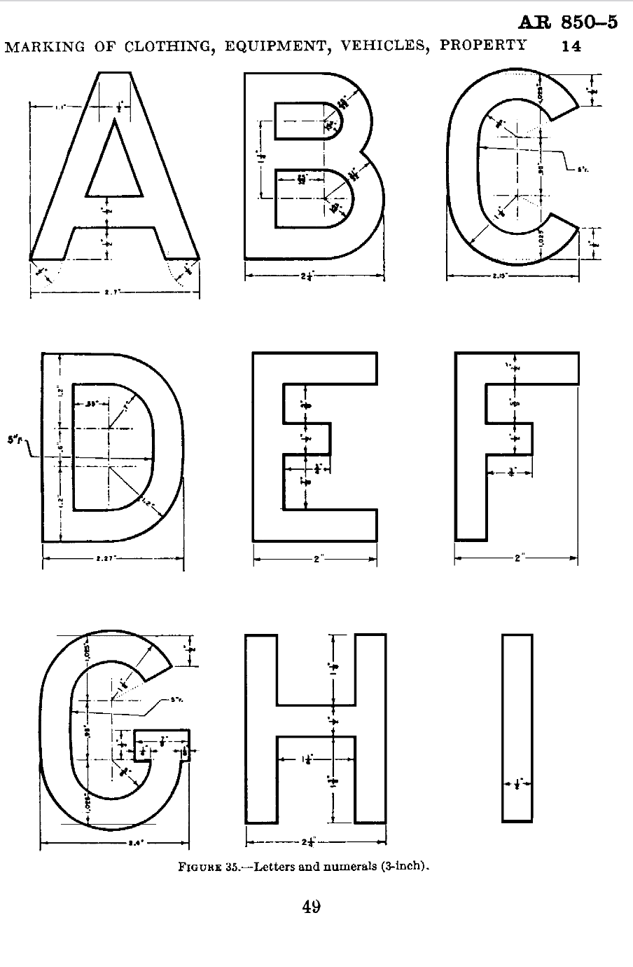
Of course, finding the letterforms was just the beginning of the battle. From here, I'll need to digitize the letterforms and turn them into a font that we can download and type with. This was a long process, so I'll keep it brief:
I took screenshots of the pages with the letterforms and uploaded them to Inkscape, a free vector editing software. Inkscape has a useful tool call "Trace Bitmap," () which traces over what it percieves to be lines in any given image. I applied this tool to the letterforms, then used the node editing tool (F2) to fix any errors the computer made. In some cases the computer traced over the drafting marking which we don't want, so I deleted those. In other cases the computer rounded corners that should be kept sharp.
Once all of the letters were traced, I exported them individually as SVG files and imported them to FontForge, a software specifically designed to let you create fonts from vector images. After messing around with the Spacing between the letters, we now have a working font.

And now you can download the font for free! It's in the Materials, Tools and Files step.
Silkscreening

In order to add labels to the pedal, well use a silk screening kit to transfer our font to the metal panels.

I started by printing my design (attached in the "Files" step) onto inkjet transparency film. I then took a mesh screen from the screen printing kit and covered it in a layer of photo emulsion and let it dry. The photo emulsion hardens when exposed to to UV light, so it can be used to transfer detailed lines from our template onto a silkscreen. Simply place your design onto to silkscreen and place it under a UV bulb for 15 minutes or so. The photo emulsion will harden everywhere that it has been exposed to light, but part covered by the design on the inkjet transparency film will remain uncurled. You can then hose down your silkscreen with water to remove the uncurled emulsion, leaving you with a highly detailed stencil. We can then press this stencil against our metal plate and apply a swipe of silkscreening ink to paint the letters. Ideally you want enamel ink for the best adhesion, but I used acrylic and it works decently well.
Putting It All Together
With all the individual components done, we can now focus on putting them all together.
The metal panels will line up snugly in their respective places. I used a drill press to bore some screw holes and screwed all the panels in place.
The electronics are the tricky part here. There’s a lot of pieces that need to fit in a small space!
The components look like a mess, so here’s a wiring diagram showing how everything should be wired:

Conclusion

This project was a long time in the making, but overall I'm happy with the sound! I actually like it way better than my cheap, store-bought guitar pedal.
A few things I would do differently:
- Use bigger breadboards for prototyping
- I like the single-knob look, but I might experiment with adding a potentiometer with an integrated switch so you can toggle between different sounds.
- Fix the LED connection in the Gerber file - the LED should connect to +9V, not ground
- Try using oak for the enclosure instead of pine for durability
If you liked this project, follow me here on instructables or on instagram @gabriel.mejia.estrella for more interesting, music-related projects : )
Video demo to come soon!
Further Reading
Electronics:
- How Class A amplifiers work: https://www.youtube.com/watch?v=mAr2AzHHepE&t=2s
History of Fuzz:
Deep Dive into the Science of Different Distortion Types:
- Guitarist-oriented article on the science of distortion - https://uveffects.com/tonelab/harmonic-series-guide/
- Book with an interesting chapter on distortion. Covers some math: https://books.google.com/books?id=nNgTAXPHWi4C&q=harmonic+distortion&pg=PA92#v=snippet&q=harmonic%20distortion&f=false
Military Manuals and WWII Manufacturing:
- Manual on Vehicle Markings and Letterforms - http://jeepdraw.com/images/AR-850-5.pdf
- WWII Carpentry Techniques: https://archive.org/details/TM5-226/page/n79/mode/2up
- Fun WWII-era video explaining chapter 3 of the above manual: https://www.youtube.com/watch?v=b_HM8HKiD-c&t=520s