PulpPro


Greetings, everyone, and welcome back, and here's something useful.
The PulpPro is a useful DIY answer for anyone interested in papier-mâché arts. This device, made from a salvaged Vegetable Chopper, streamlines the process of converting paper trimmings into smooth pulp.
Our goal here was to simplify the paper pulp-making process, which involved manually mixing paper with water, which took time to soften the paper, and then manually mixing the solution to make the pulp. This process was extremely time-consuming, and I was going to be working on a paper pulp project in the future, so we created the PulpPro to simplify the process and make the task easier.
We took the jar and blade from a vegetable chopper, removed the mechanical element, and installed a motor to spin the blade. For controlling the motor, we designed a Custom XIAO ESP32 S3-powered Motor Driver Board with an OLED screen that displays the motor's run time.
We designed the body in Fusion360 and even added a handle to allow it to be easily carried around or moved from one location to another.
This device works by connecting a gear motor to the Blade part, which revolves inside the Jar. We power the motor with an onboard battery, and to regulate the motor speed and time, we utilize a microcontroller setup with buttons as input and a display to show the device's run time.
To test this project, we also created a small card out of paper pulp that we prepared inside our PulpPro.
This whole Instructables is about the Build process of this project, so let's get started with the build.
Supplies
These are the materials used in this project:
- Custom PCBs (Provided by Seeed Studio Fusion)
- XIAO ESP32 S3 DEV BOARD
- SSD1306 OLED Screen
- AMS1117 Voltage Regulator 5V
- 10uF Capacitor 1206 Package
- 1uF Capacitor 1206 Package
- 10k Resistor 0805 package
- AO4406 N Channel Mosfet IC SOIC8 Package
- CON7 Female header pin connector x 2
- lever switch
- 12V battery Pack
- 12V Power Source (adaptor/smps)
- DC barrel jack
- Push Buttons
- M2 screws
- M3 Threaded Inserts
- M3 bolts
- 3D printed parts
- Vegetable Chopper
3D DESIGN


We started our project by designing our own blender, using an existing vegetable chopper's jar and blade. Jar and Blade were difficult to 3D print because the blade needed to be created by retrofitting a paper cutter blade, and the jar could be 3D printed but there would be a water leak issue, so we used the jar and blade from the vegetable chopper. We designed the remaining elements, which comprised the base body, which houses the motor and battery pack within, and the lid, which is put over the base body and holds the circuit in place. To keep the motor in place, we designed a motor holder that attaches to the bottom side of the base body.
The whole model was made in Fusion360, and we incorporated industrial design into this project by conducting research on the design of various types of blenders, and then we came up with our own sleek design that mounts on top of the jar and appears to be an extension of the jar rather than something retrofitted.
Also, we divided the Base body into two sections so that we could print them both fast. The entire time for printing the Base body was more than 24 hours, but by splitting the model in two halves, we were able to cut the time to 10 hours for each print.
we created a custom circuit with four mounting holes that are attached to the lid using four screw bosses. On the circuit, we've added an XIAO Microcontroller model, followed by the SSD1306 OLED screen, four buttons, and a barrel DC jack. We will use the dimensions from this Cad file to create the board outline and position components during the PCB editing phase.
To give the 3D printed parts a visually appealing look, we 3D printed the base body in transparent PLA and the remaining components in brown PLA.
XIAO MOTOR DRIVER - CIRCUIT DESIGN
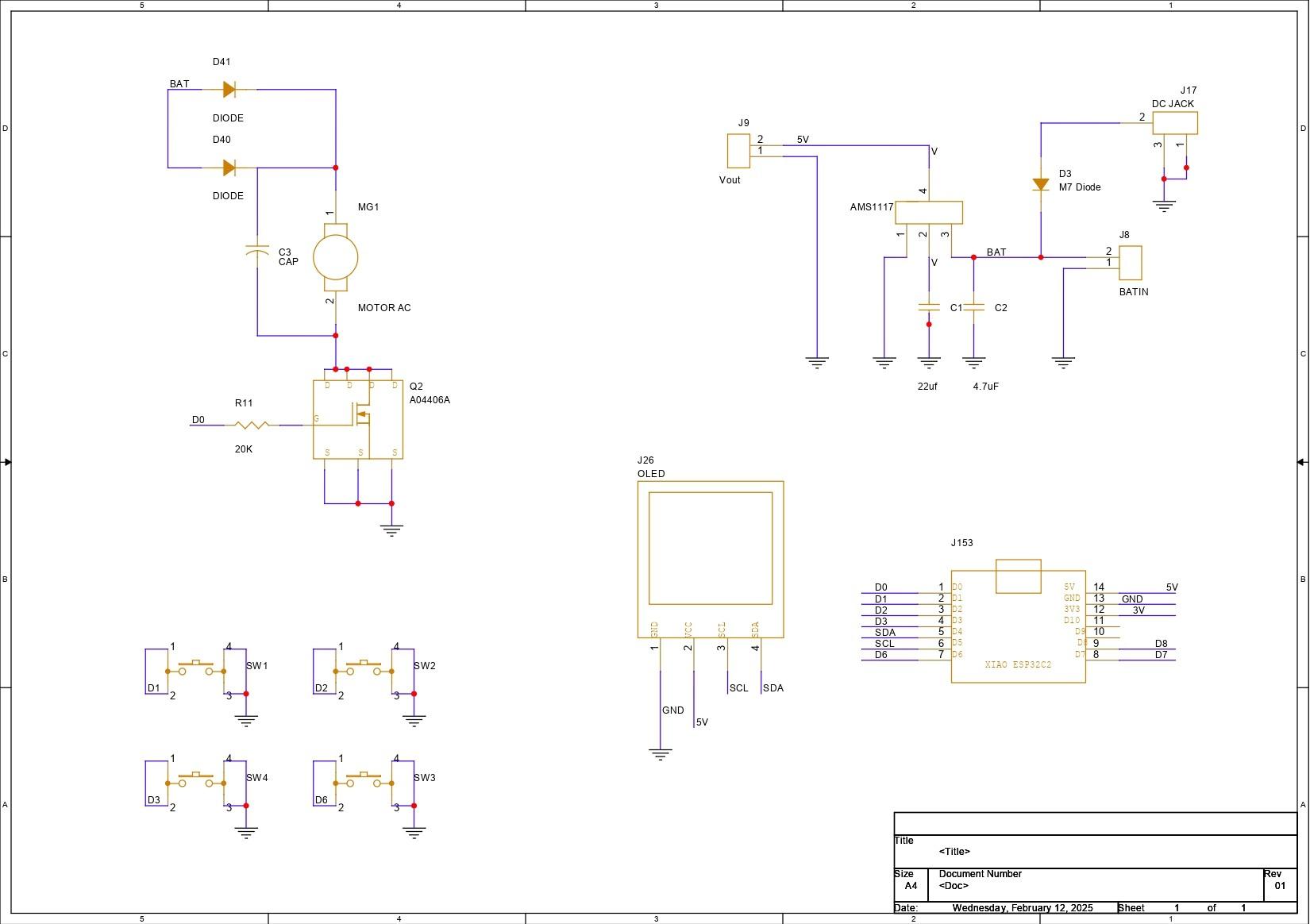

We began the Motor Driver Board design process by constructing a simple schematic that included an XIAO ESP32 S3 microcontroller linked to an AO4406A N Channel Mosfet IC. We are using the Mosfet as a switch setup, with our motor linked to the Mosfet and a 10K resistor connected to the gate of the mosfet via GPIO0 of the XIAO MCU. We can control this mosfet using GPIO0. In addition, we added four buttons with GPIOs 1, 2, 3, and 6.
An OLED display is also used and is connected to XIAO's SDA and SCL pins, which are GPIO4 and GPIO5.
In this arrangement, we're utilizing a 12V battery and a 12V motor, but the XIAO is a 5V device, which means any voltage above 5V would fry the controller. To convert 12V to a stable 5V for XIAO and display operation, we used an AMS1117 voltage regulator configuration, which consists of an AM1117 coupled to two capacitors at the input and output.
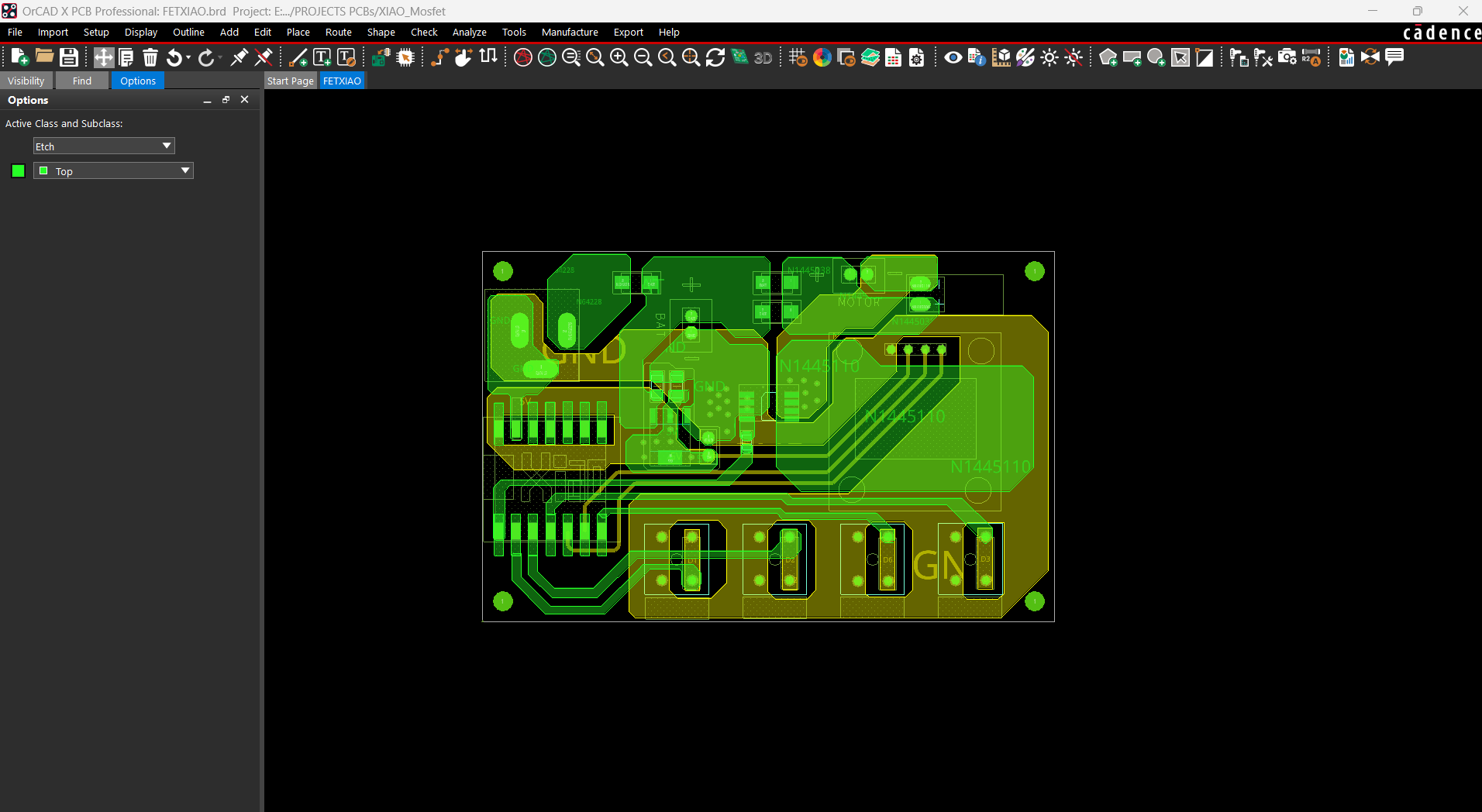
After finalizing the schematic, we prepare the board design for this project by following the board outline from the cad design and arranging all of the components according to the layout.
We complete the PCB design and prepare the Gerber data, which will then be shared with a PCB manufacturer for samples
SEEED FUSION PCB SERVICE


Following the completion of the Gerber data, we uploaded the file to Seeed Fusion's website and placed an order for a RED Solder mask with white silkscreen.
PCBs were received in a week, and their quality was super good considering the rate, which was also pretty low.
Seeed Fusion PCB Service offers one-stop prototyping for PCB manufacture and PCB assembly, and as a result, they produce superior-quality PCBs and fast turnkey PCBAs within 7 working days.
Seeed Studio Fusion PCB Assembly Service takes care of the entire fabrication process, from Seeed Studio Fusion Agile manufacturing and hardware customization to parts sourcing, assembly, and testing services, so you can be sure that they are getting a quality product.
After gauging market interest and verifying a working prototype, Seeed Propagate Service can help you bring the product to market with professional guidance and a strong network of connections.
PCB ASSEMBLY PROCESS


- The PCB assembly process begins by applying solder paste to each SMD component pad one at a time with a solder paste dispensing syringe.
- We then use an ESD Tweezer to pick and install each component in its proper location.
- The PCB is then placed on the reflow hotplate, which heats it from below up to the solder paste melting temperature in order to melt the solder paste and permanently solder all of the SMD component pads.
- We then replaced them with through-hole components such as push buttons, a CON7 header pin for the XIAO Dev board, a DC barrel jack connector, and an OLED display.
- The board is then flipped over, and all through-hole components and pads are soldered to the PCB with a soldering iron.
- Finally, we install the XIAO ESO32 S3 DEV Board over the CON7 Header Pin Connector.
CODE
Now let's have a look at our code and it's a simple one.
lets have a Short Breakdown of the code.
We first start by inclding the nessasary libraries that we are going to use in this project.
OLED Display Setup
OLED_WIDTH and OLED_HEIGHT define the dimensions of the OLED display (128x64 pixels), we also included the I2C address of the OLED which is commonly 0x3C.
Adafruit_SSD1306 display(OLED_WIDTH, OLED_HEIGHT); initializes the OLED display object with its dimensions.
Pin Definitions
We next decalre which Pin is connected to which GPIO.
Variables
motorRunTime: Stores the default timer duration for the motor in milliseconds (60,000 ms = 1 minute).
timeAdjustment: Amount to increase or decrease the motor timer when buttons are pressed (10 seconds = 10,000 ms).
motorRunning: A flag indicating whether the motor is ON (true) or OFF (false)
motorStartTime: Tracks the time when the motor starts, used for countdown logic.
Button State Variables: Track the previous and current states of the buttons for proper press detection.
Setup Function
This section configures the motor and button pins by specifying their modes (OUTPUT for the motor pin and INPUT_PULLUP for the buttons), with the motor switched off by default. To facilitate debugging, the serial transmission is set to a baud rate of 115200. The OLED display is also initialized using the begin() function and the supplied I2C address, and the application terminates if the initialization fails. After ensuring that the display is ready, the screen is cleared and a welcome message, "Paper Mache Maker," is displayed for two seconds to signify that the setup was successful, followed by a call to updateDisplay() to display the initial timer value. Overall, this function sets up the hardware and display for the main program loop.
Loop Function
1. Start/Stop Button Logic
Detects a press-and-release event for the Start/Stop button and Toggles the motor state (ON/OFF) based on button input.
2. Add Time Button Logic:
This Increases the motor timer by timeAdjustment (10 seconds) when the button is pressed and updates the OLED.
3. Subtract Time Button Logic:
This Reduces the motor timer by timeAdjustment if the timer is greater than 10 seconds.
4. Countdown and Motor Off:
Continuously checks if the motor's runtime has expired:
- If expired, turns off the motor and updates the display.
- Otherwise, displays the remaining time in seconds.
Our Code controls the motor with a configurable timer displayed on an OLED. The buttons allows to start/stop the motor, increase or decrease its runtime, and the display updates during operation.
MOTOR TEST


After uploading code to our Motor Driver board, we used a soldering iron to connect a 12V Gear Motor to our Circuit's Motor connector.
A 12V power supply is linked via the onboard Barrel DC connector.
We set the run time using the Timer+ and Time- buttons, which is displayed on the LCD screen, and the motor begins to rotate when we push the Start/Stop button.
This demonstration confirms that our setup is operational, and we can now proceed to the body assembly procedure.
BASE BODY ASSEMBLY


- We begin the body assembly procedure by joining the two main body pieces that were printed separately by placing the upper portion over the bottom part and then permanently securing both of them with superglue.
- We inserted M3 threaded inserts into the two holes on the left and right faces of the base body. We use our soldering iron in conjunction with a Threaded insert holding kit to heat the threaded insert until it slides into its position by melting the plastic surrounding it.
MOTOR HOLDER ASSEMBLY


- We now begin the motor holder assembly by inserting four M3 threaded inserts into the holes we modeled on the part. These threaded inserts will be used to mount the gear DC motor to this part.
- We begin by placing the insert over the hole, then using the soldering iron to press it down. The insert will melt the plastic around it and slide down into position. We do this for four inserts.
- Next, we align the mounting holes on the Gear DC Motor and secure it to the Holder part with four M3 bolts.
BASE BODY-MOTOR HOLDER ASSEMBLY


- The Motor Holder Assembly is now attached to the base body's bottom side, and we utilize Four m2 screws to secure both the base body and the Holder assembly together.
- The Lever Switch is now placed in its proper position and secured with the locking nut that came with it.
- The 12V Lithium Battery Pack is now lowered down inside the Base Body, exactly next to the Gear motor.
- The battery pack's VCC is attached to the switch's NC terminal, and an additional wire is soldered to the switch's NO terminal. We inserted the switch between the battery's VCC and the circuit to disconnect the main power.
- We use hot glue to keep the battery lock in place.
BLADE ADAPTOR


Because the Blade part we're using has a hexagon-shaped mounting slot and the motor we're using has a D shaft, we had to design a part that will work as an adapter to link the motor's D shaft to the Blade's hexagon slot.
This adapter part is first attached to the motor's shaft, and then the blade section is placed on it.
Next, we attached the Jar, which keeps the Blade section locked in place and allows it to only rotate in place.
LID & CIRCUIT ASSEMBLY


- The Lid Part is now positioned over the base body, and all cables, including the battery and motor wires, are routed via the Lid Part's rectangular opening.
- The lid is then secured to the base body with two M2 screws.
- We next used a soldering iron to connect the battery terminals that were positive from the switch and GND to the circuit's battery terminals. We then connected the motor terminals to the circuit's motor terminal.
- All wires are then tucked within, and the circuit board is positioned over the mounting screw bosses. We then use four m2 screws to secure Circuit to the Lid part.
HANDLE ASSEMBLY


Finally, we place the Handle and secure it to the Base Body with two M3 Bolts.
This completes the assembly process, and our device is now ready.
RESULT


This is the end result of this small but useful build, PulpPro, a DIY Paper Mache making machine that converts paper into pulp using a cutting blade powered by a DC Gear motor.
To use this device, we first turn on the Lever switch, which powers the device. Once powered on, we are greeted with a Paper Mache Machine welcoming screen and a timer of 60 seconds is displayed. We have set the Default Run Time to 60 seconds.
The Time + and Time - buttons allow the user to increase or reduce the 60-second default time. After selecting the time parameters, we may start the device by hitting the Start/Stop button, which will start the motor at the specified run time. The timer begins as soon as the device is turned on and the motor begins to rotate.
PAPER MACHE PREP WORK


Now comes the main objective of our project: to create paper pulp with our Pulp Pro. We're using standard notebook paper shredded into small bits to make it easier for Blade to break down.
We added craft white glue to act as a binding agent for the pulp.
Finally, we added lukewarm water, placed the base body assembly on top of the jar, attached the blade to the motor, and set the timer for 1000 seconds.
CONCLUSION


After running the motor for 1000 seconds, we get a Fine-grade pulp in which all of the paper is finely blended to form a paste-like substance that can be used for making handmade paper sheets, paper sculpture, and other creative projects. Using glue helped the pulp bind paper together, and the entire process took 1000 seconds, which is far faster than the usual method of soaking paper in water for half a day and then mixing by hand to produce the same grade pulp mix.
Using this pulp, we first form a ball and remove extra water from it by compressing it in our hands, which removes the majority of the water from the pulp ball.
We then flattened it on a smooth acrylic board and made a naan- or Pizza-like shape that was extremely thin. After letting this dry in the sun for a few hours, we have a sturdy piece of custom-made paper, which is great. We can use this paper to build a little cover for a notepad or get creative and design things like greeting cards, bookmarks, and more.
Our goal of creating an instrument that would make this process much faster and more refined has been achieved, and we will now use this device in an upcoming project that will use cardboard to manufacture little germination pots. More on that in a future article.
Overall, this project is now concluded and requires no further revision.
Leave a comment if you need any help regarding this project. This is it for today, folks.
Thanks to Seeed Studio Fusion for supporting this project.
You guys can check them out if you need great PCB and stencil service for less cost and great quality.
And I'll be back with a new project pretty soon!