RainGlow: Make Your Umbrella Smarter With an LED Rain Alert
by taifur in Circuits > Wireless
1400 Views, 14 Favorites, 0 Comments
RainGlow: Make Your Umbrella Smarter With an LED Rain Alert
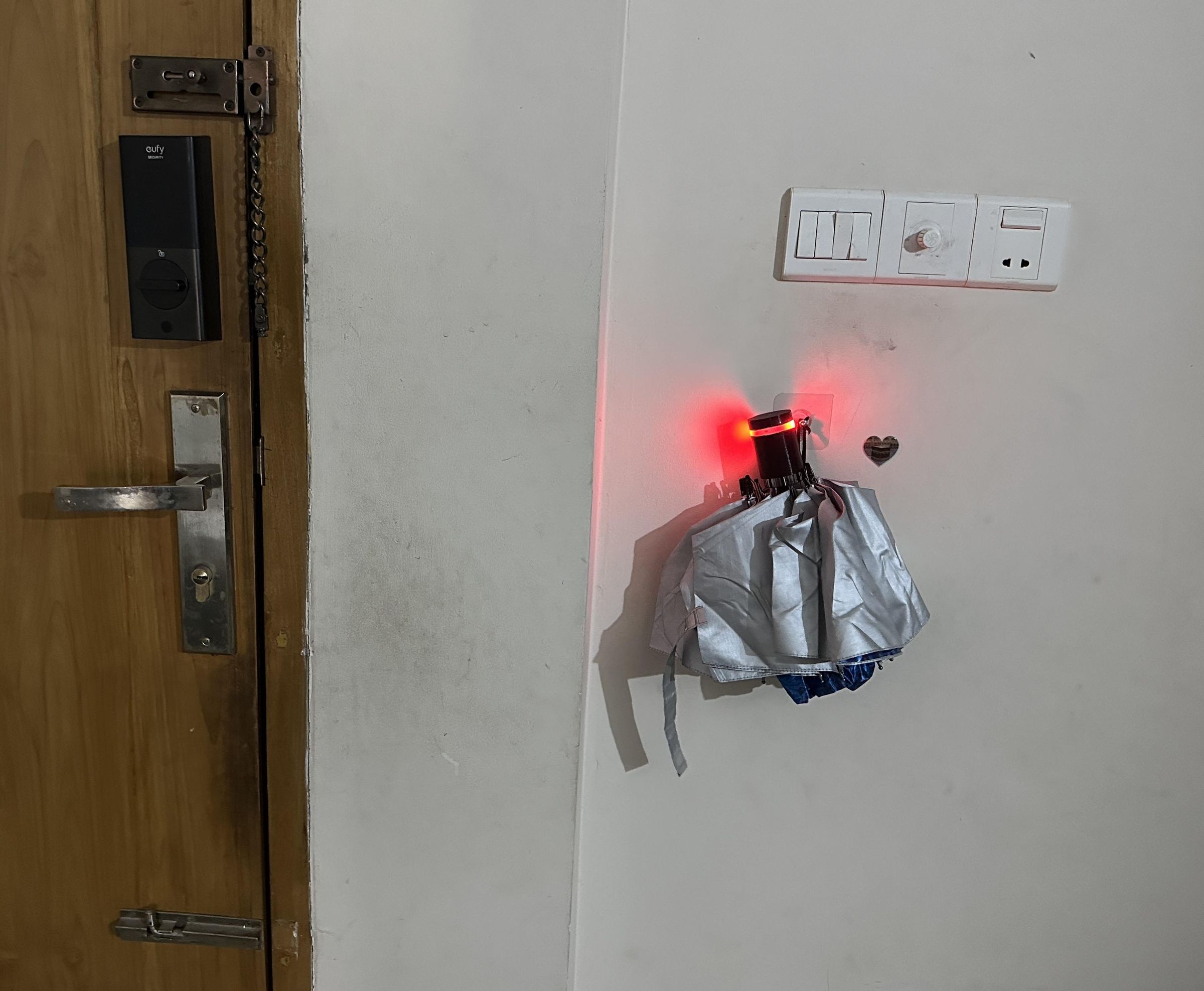
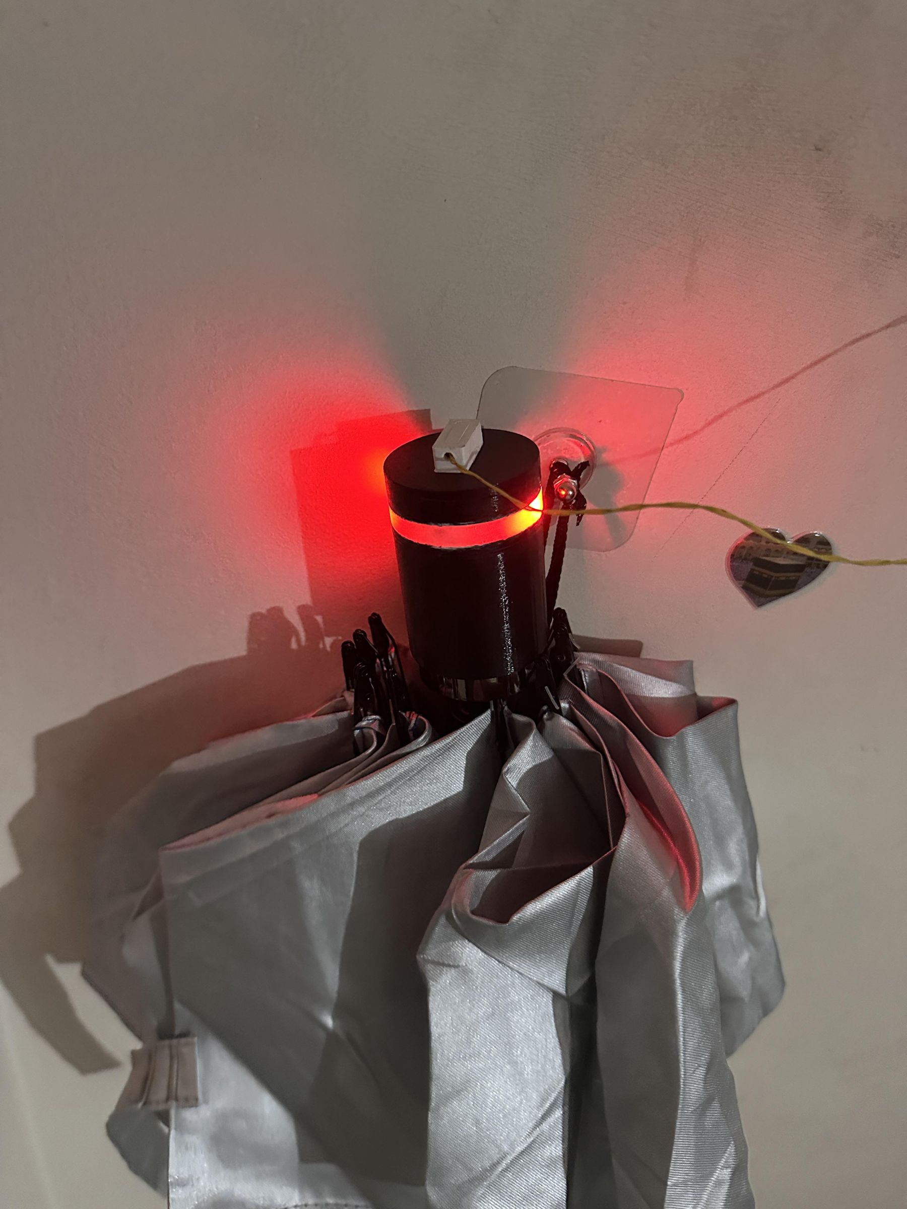
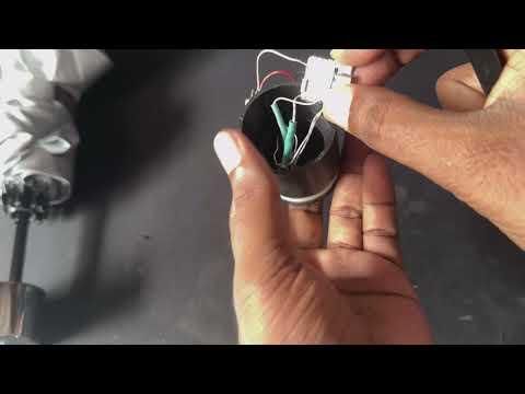
Have you ever left home without an umbrella because the sky looked clear, only to get caught in an unexpected rain shower? RainGlow is a simple, battery-powered smart attachment that fits onto the handle of almost any umbrella and helps solve that problem.
Instead of checking the weather forecast every time you go outside, RainGlow provides a clear LED indication whenever there is a significant chance of rain. Before leaving home, simply look at your umbrella—if the LED lights up, it's a reminder that you may need it today.
The project is designed to be compact, low-power, and easy to build using affordable electronic components. It is also reusable, meaning you can attach it to your favorite umbrella without permanently modifying it. Whether you're a beginner looking for a fun electronics project or a maker interested in practical IoT gadgets, RainGlow is a great weekend build.
In this Instructable, I'll show you how to design, assemble, program, and test RainGlow step by step, so you can build your own smart umbrella companion and never be surprised by the weather again.
Supplies
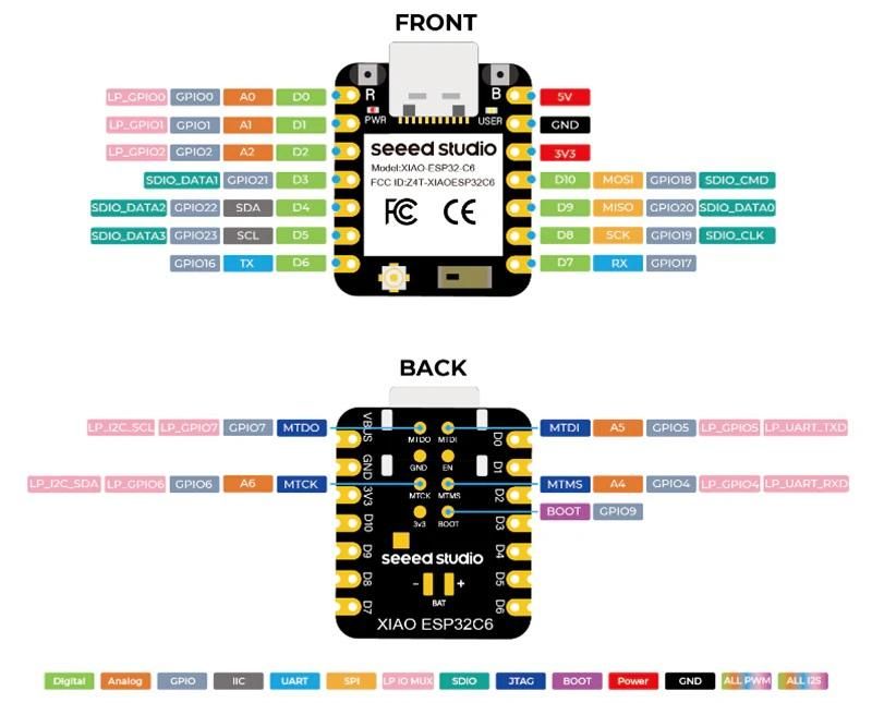
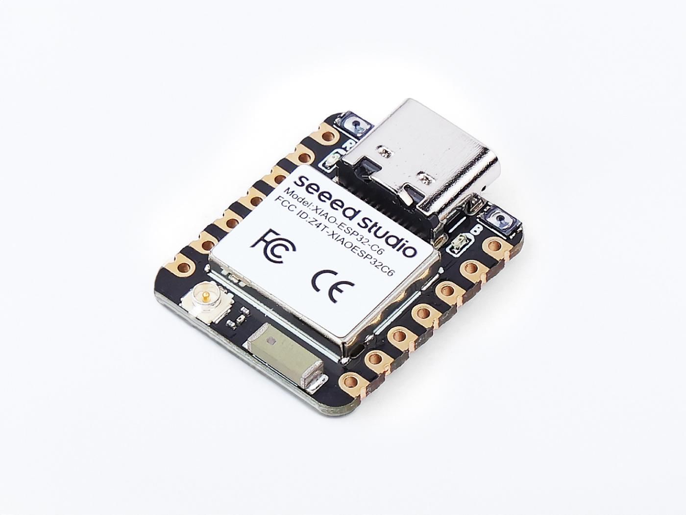
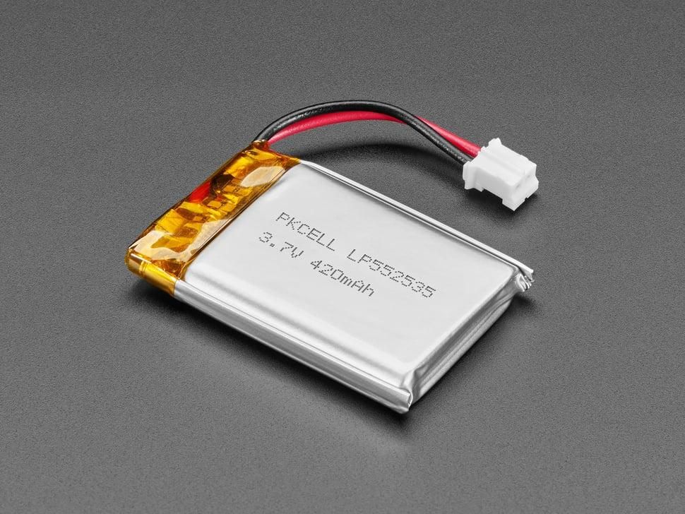

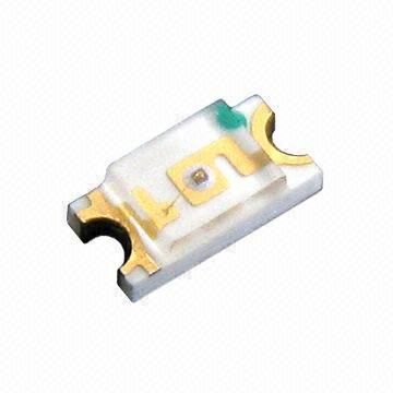
The following hardware components were used in the project:
Hardware Components:
- Seeed Studio XIAO ESP32-C6 (buy from Seeed Studio): XIAO ESP32-C6 is a cost-effective MCU based on Espressif’s ESP32-C6. Designed with the thumb-size footprint and a single-sided mount of the XIAO Series, it's perfect for space-limited projects like an IoT umbrella.
- 1206 SMD LED Red (buy from AliExpress)
- 450mAh Li-ion Battery (buy from AliExpress)
- 2Pin DC Magnetic Pogo Pin Connector male and female (buy from AliExpress)
- Ribbon Cable Wire (buy from AliExpress)
- Clear Epoxy Resin (buy from AliExpress)
Tools:
- Adjustable Soldering Iron 60W (buy one from AliExpress)
- Electronic Diagonal Pliers/Side Cutting Nippers/Wire Cutter (buy one from AliExpress)
- Access to a 3D Printer (buy one from AliExpress)
Disclosure: A few of the product links provided are affiliate links. This means I may receive a small commission if you make a purchase through them, without affecting the price you pay. Your support helps fund future builds and documentation.
3D Design & Printing
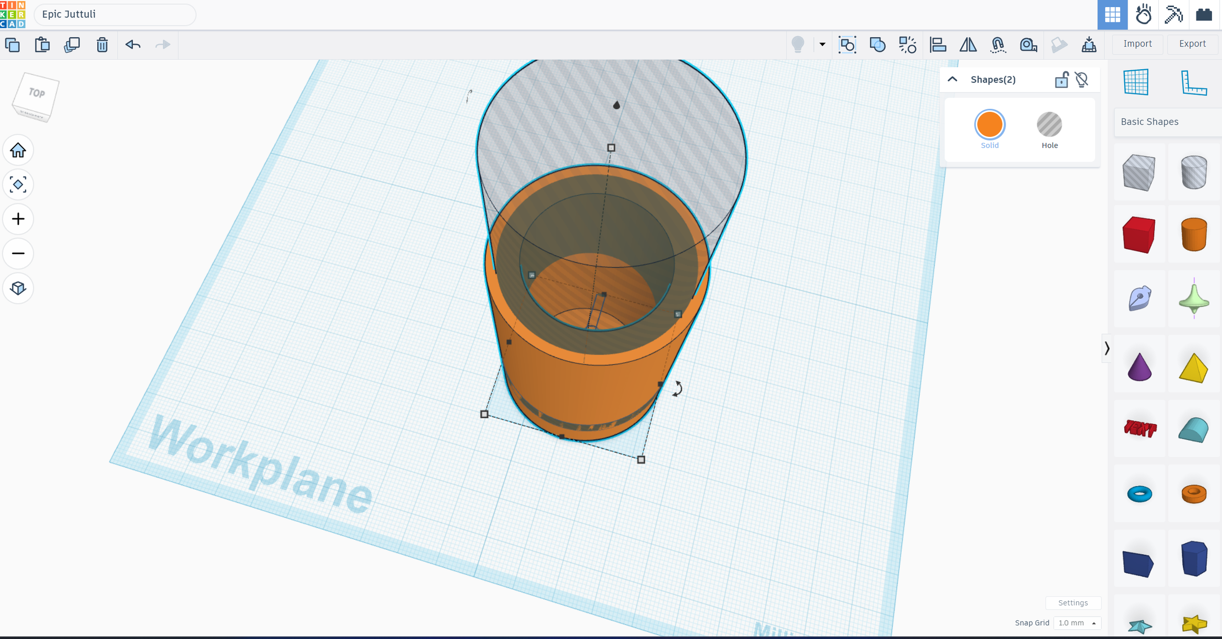
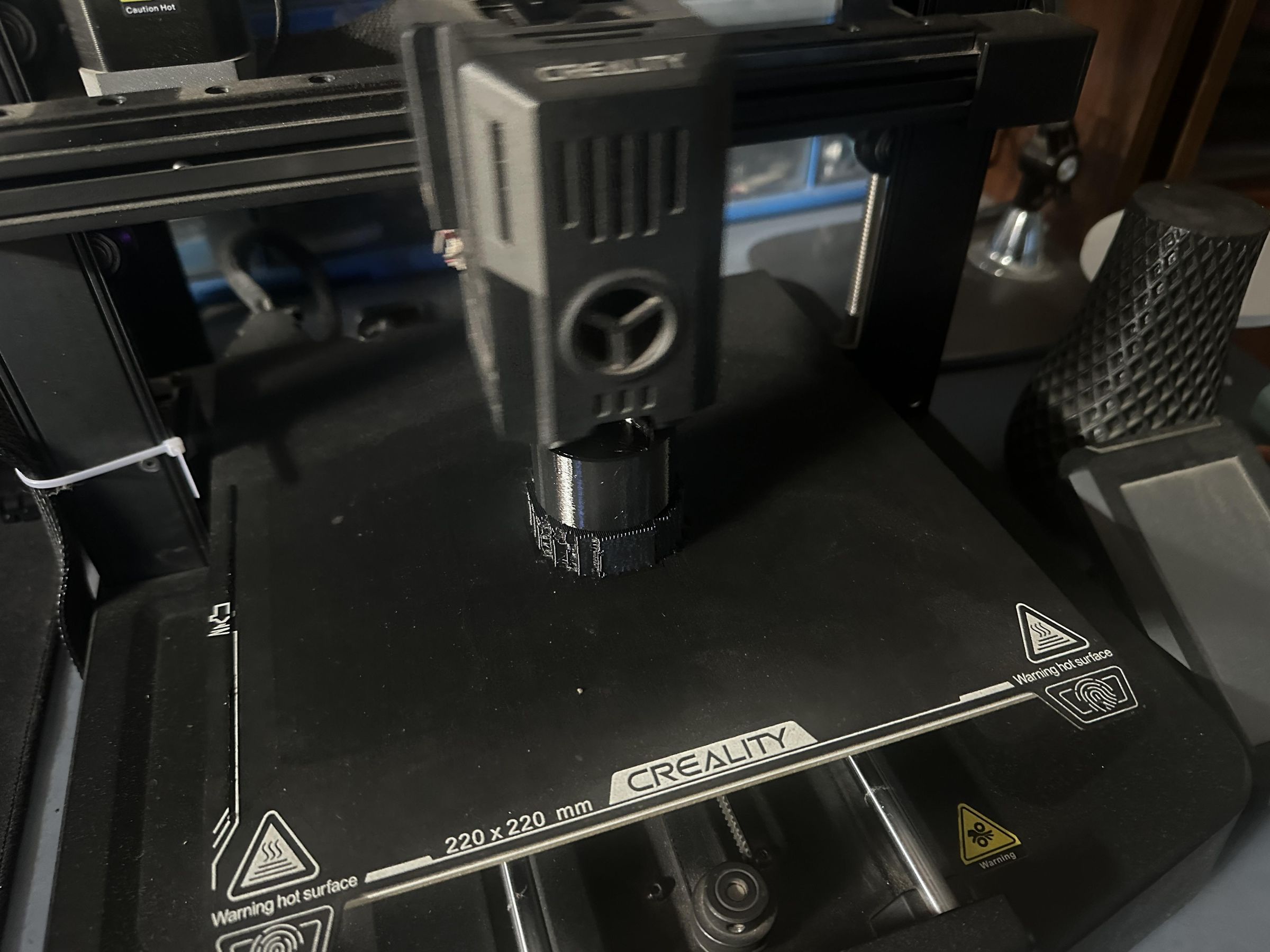
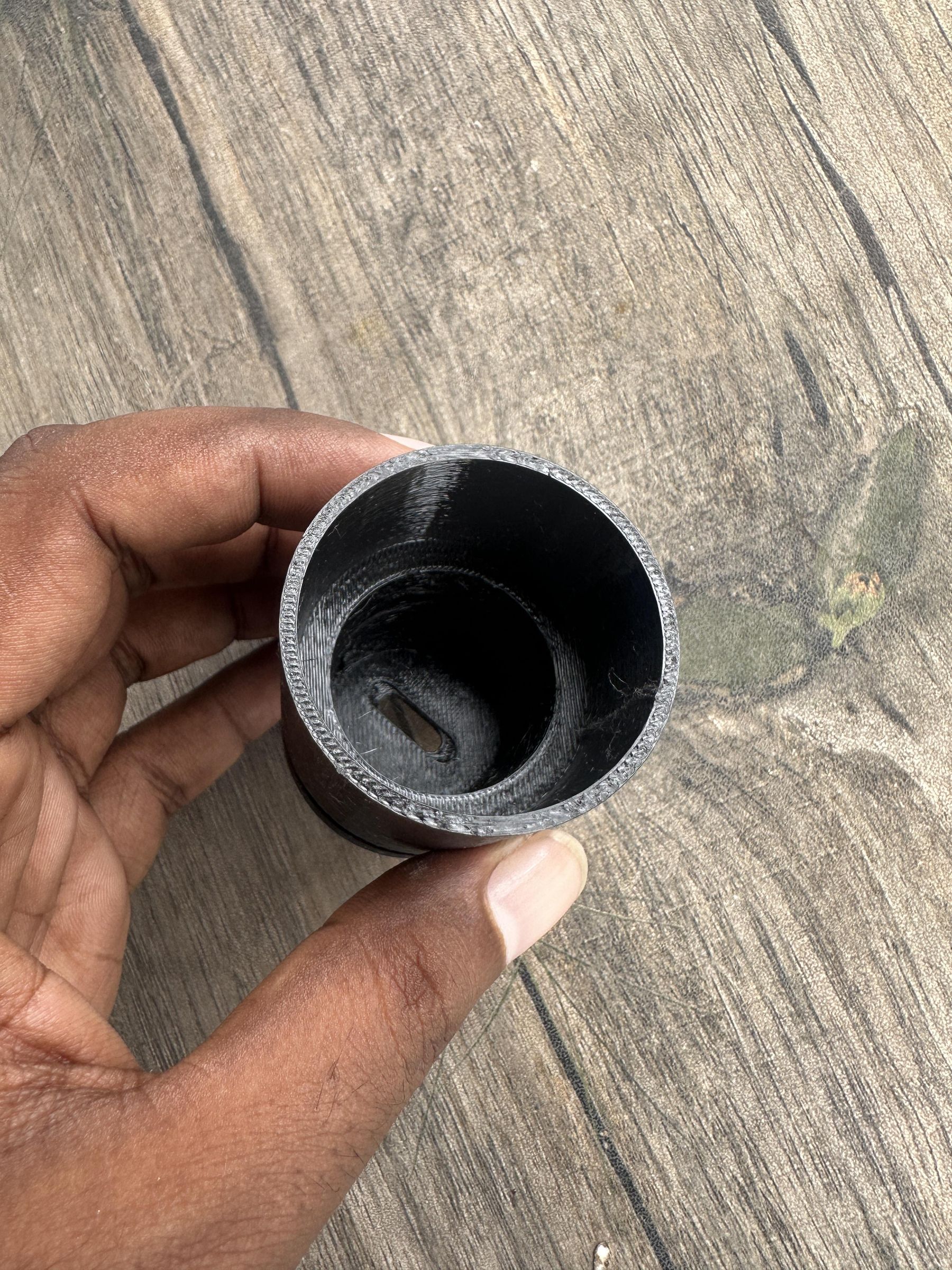
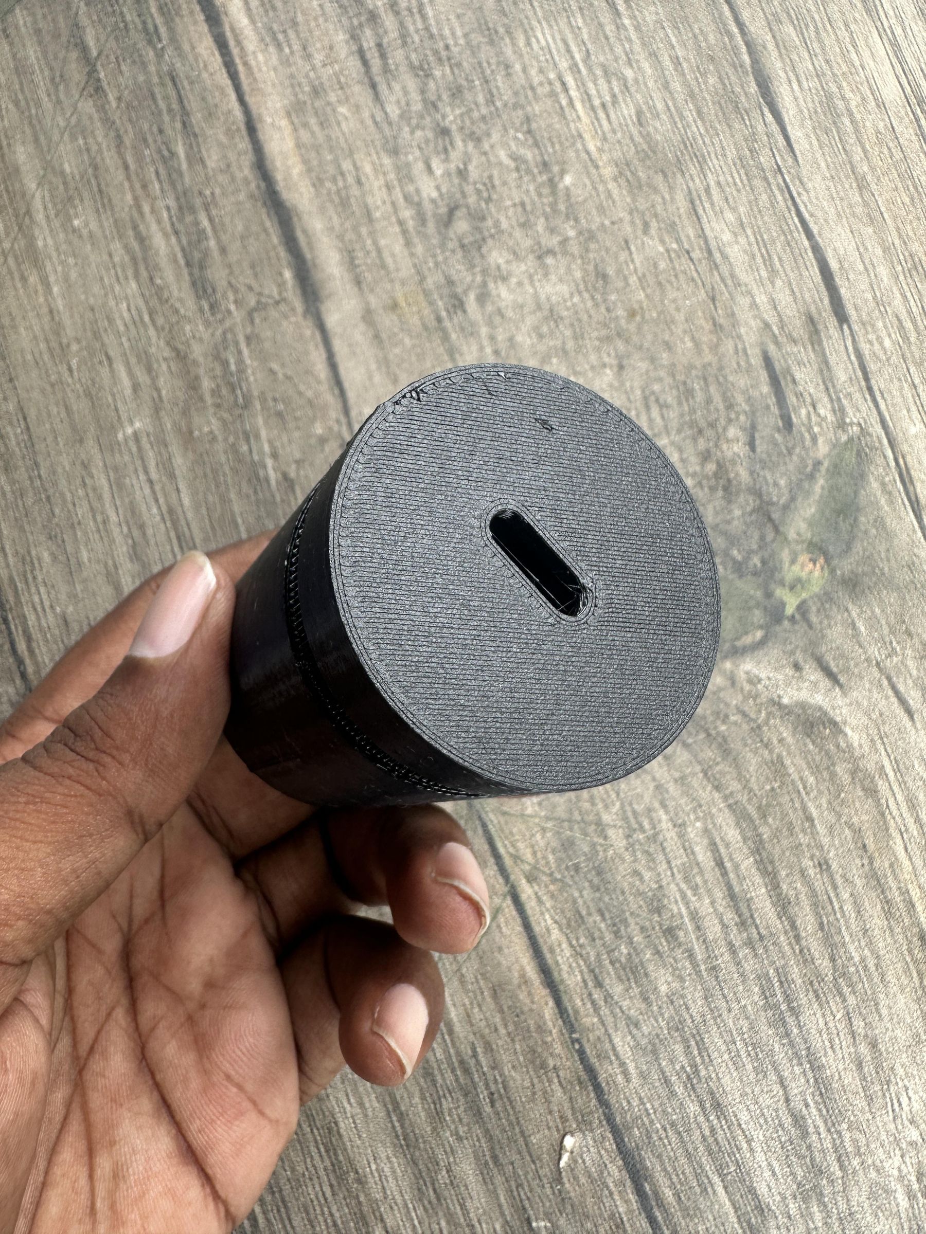
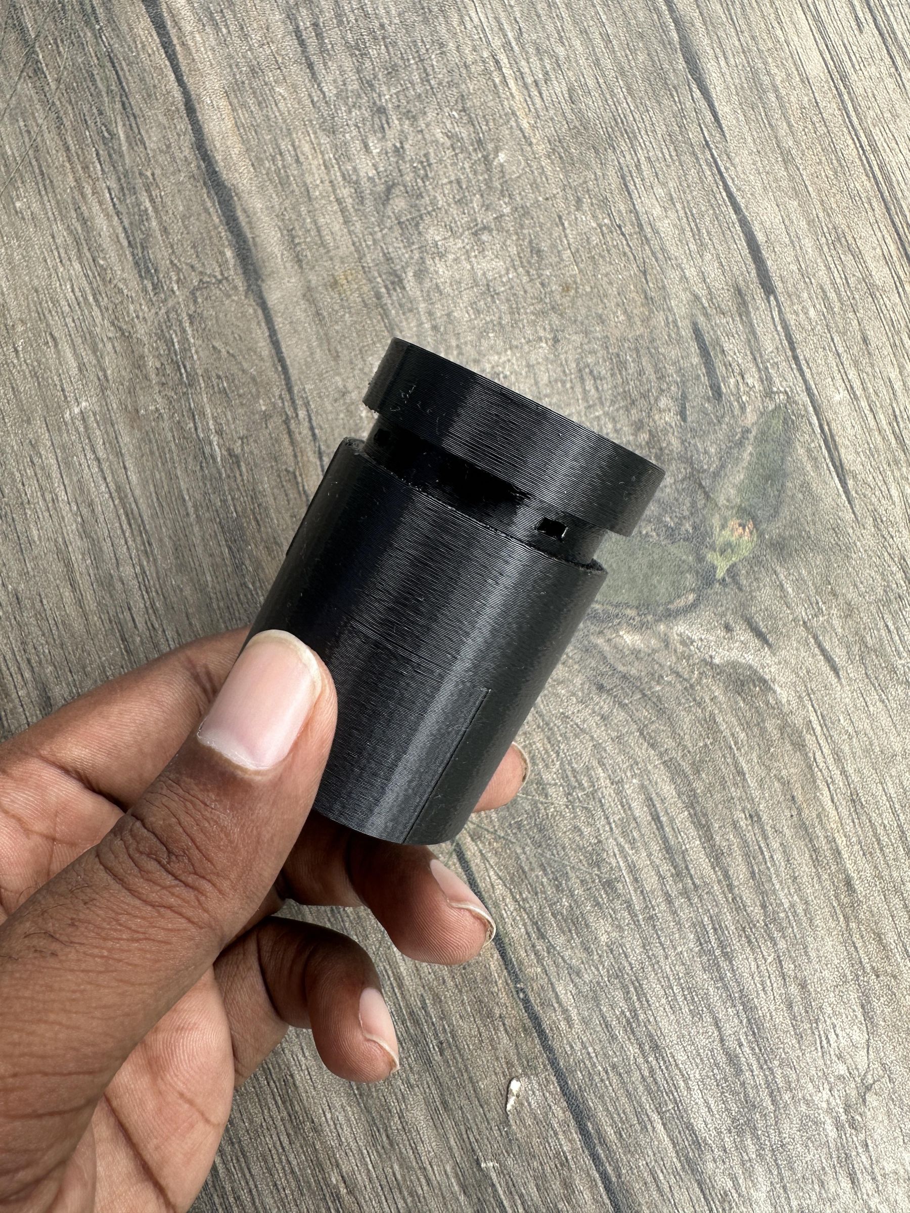
The first step in building RainGlow is designing a custom enclosure that can securely attach to an existing umbrella handle while protecting all of the electronics.
Since every umbrella has a different handle design, I wanted to create an attachment rather than modify the umbrella itself. The enclosure simply slides onto the top of the umbrella handle, making it easy to install or remove without damaging the umbrella.
The enclosure has been designed with several important features:
- Electronics compartment: A dedicated space to house the Seeed Studio XIAO ESP32-C6, battery, LED, switch, and other electronic components.
- Transparent LED window: A circular opening on the front of the enclosure where the status LED is mounted. After assembly, this opening will be filled with clear epoxy resin. The epoxy serves two purposes: it protects the LED from moisture and dust while also diffusing the light, making the rain alert visible from multiple angles.
- Umbrella handle slot: The top of the enclosure is left open so it can slide over the existing umbrella handle, allowing the attachment to fit securely without permanently altering the umbrella.
- Compact and lightweight design: Since the device will be carried every day, I kept the enclosure as small and lightweight as possible while still providing enough room for all the components.
I designed the enclosure using Tinkercad. Although it is a beginner-friendly CAD tool, it is powerful enough for creating simple functional enclosures like this one. The drag-and-drop interface makes it easy to adjust dimensions, add mounting features, and refine the design before printing.
After finalizing the model, I exported it as an STL file and printed it using a standard FDM 3D printer. You can easily modify the dimensions of the design in Tinkercad to fit your own umbrella handle or accommodate different electronic components.
In the next step, we'll prepare the electronic components and assemble the hardware inside the enclosure.
Downloads
Circuit Connection & Testing
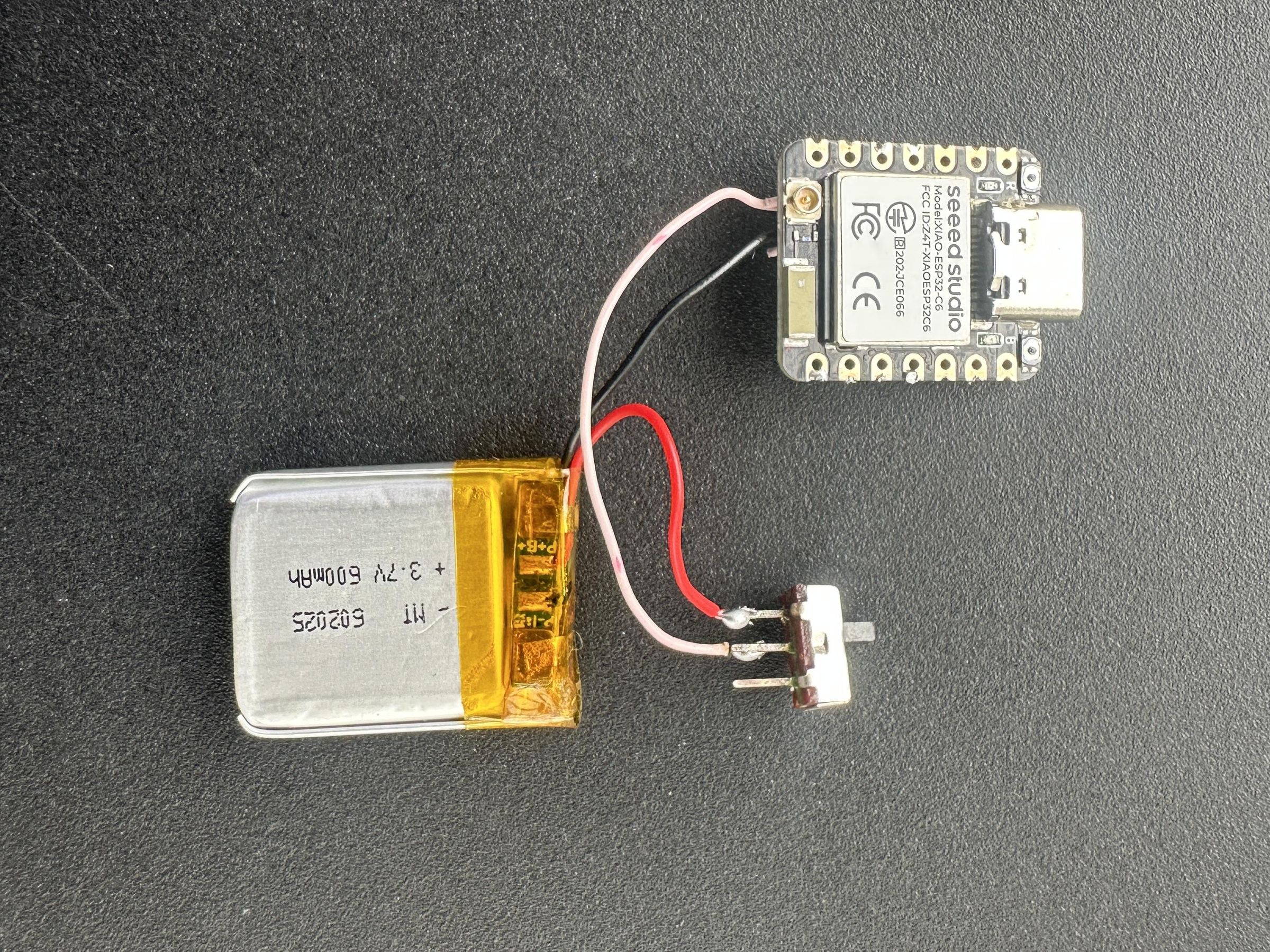
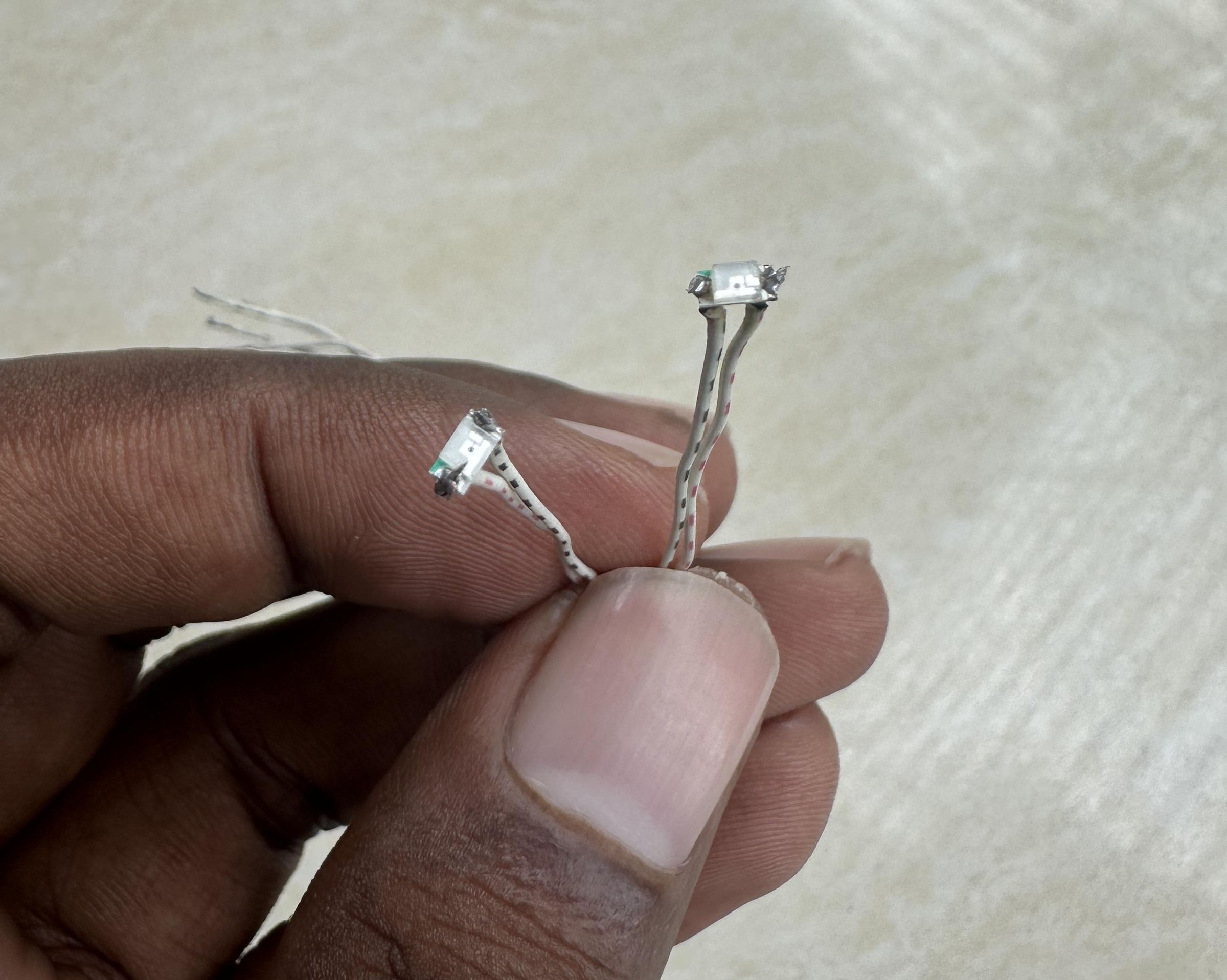
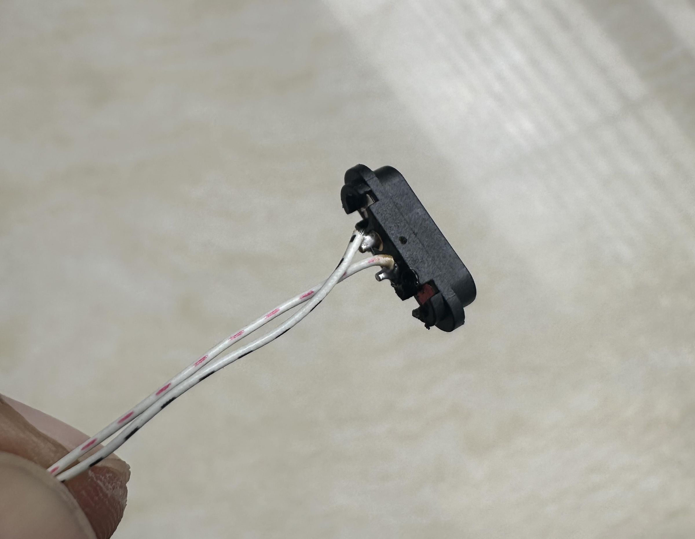
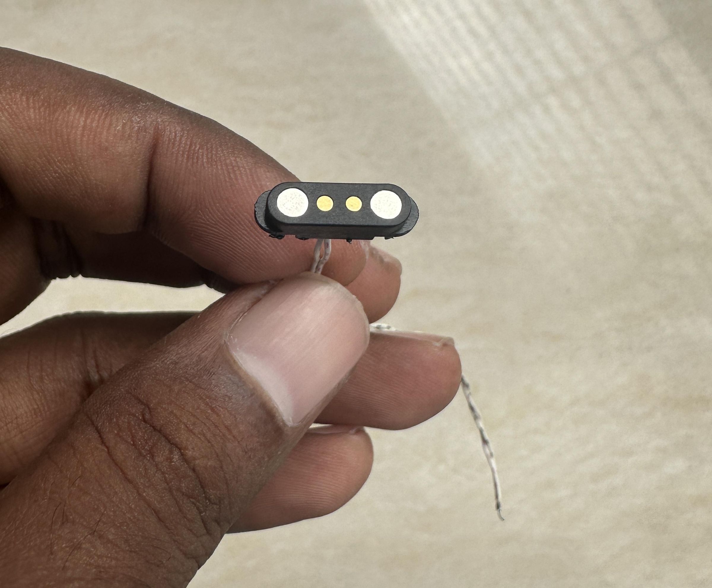
One of the goals of RainGlow was to keep the electronics as simple as possible. Fewer components mean lower power consumption, improved reliability, and an easier assembly process.
Components Used
- Seeed Studio XIAO ESP32-C6
- 2 × LEDs (Rain Status Indicators)
- 2 × 100 Ω resistors
- 3.7 V Li-Po battery
- Mini sliding switch
- Magnetic pogo pin charging connector
- Hook-up wire
LED Connections
The rain indication is provided by just two LEDs, keeping the design simple while minimizing battery consumption.
- LED 1
- Anode → D9 through a 100 Ω resistor
- Cathode → GND
- LED 2
- Anode → D10 through a 100 Ω resistor
- Cathode → GND
Using separate GPIO pins allows different indication patterns to be programmed in the future if desired.
Battery Connection
The Seeed Studio XIAO ESP32-C6 includes a built-in Li-Po battery charging circuit, eliminating the need for an external charging module.
The Li-Po battery is connected to the battery pads on the underside of the XIAO board. A small sliding switch is placed in series with the positive battery lead so the entire device can be powered off when it is not in use.
Battery Positive → Sliding Switch → BAT+ pad on the XIAO
Battery Negative → BAT− pad on the XIAO
This simple arrangement allows the battery to remain connected while providing an easy way to completely disconnect power.
Charging Connector
To avoid opening the enclosure every time the battery needs charging, I added a magnetic pogo pin connector.
The connections are straightforward:
- Pogo Pin Positive → VBUS on the XIAO ESP32-C6
- Pogo Pin Ground → GND
This allows the battery to be recharged externally without removing the electronics from the enclosure. The magnetic connector is also convenient because it automatically aligns during charging and helps maintain the water-resistant design.
Since the XIAO already includes the charging circuitry, supplying 5 V through the VBUS pin is all that's required to recharge the battery safely.
Overall, the entire circuit consists of only a handful of components, making RainGlow compact, power-efficient, and easy to reproduce.
Creating the Glowing LED Ring
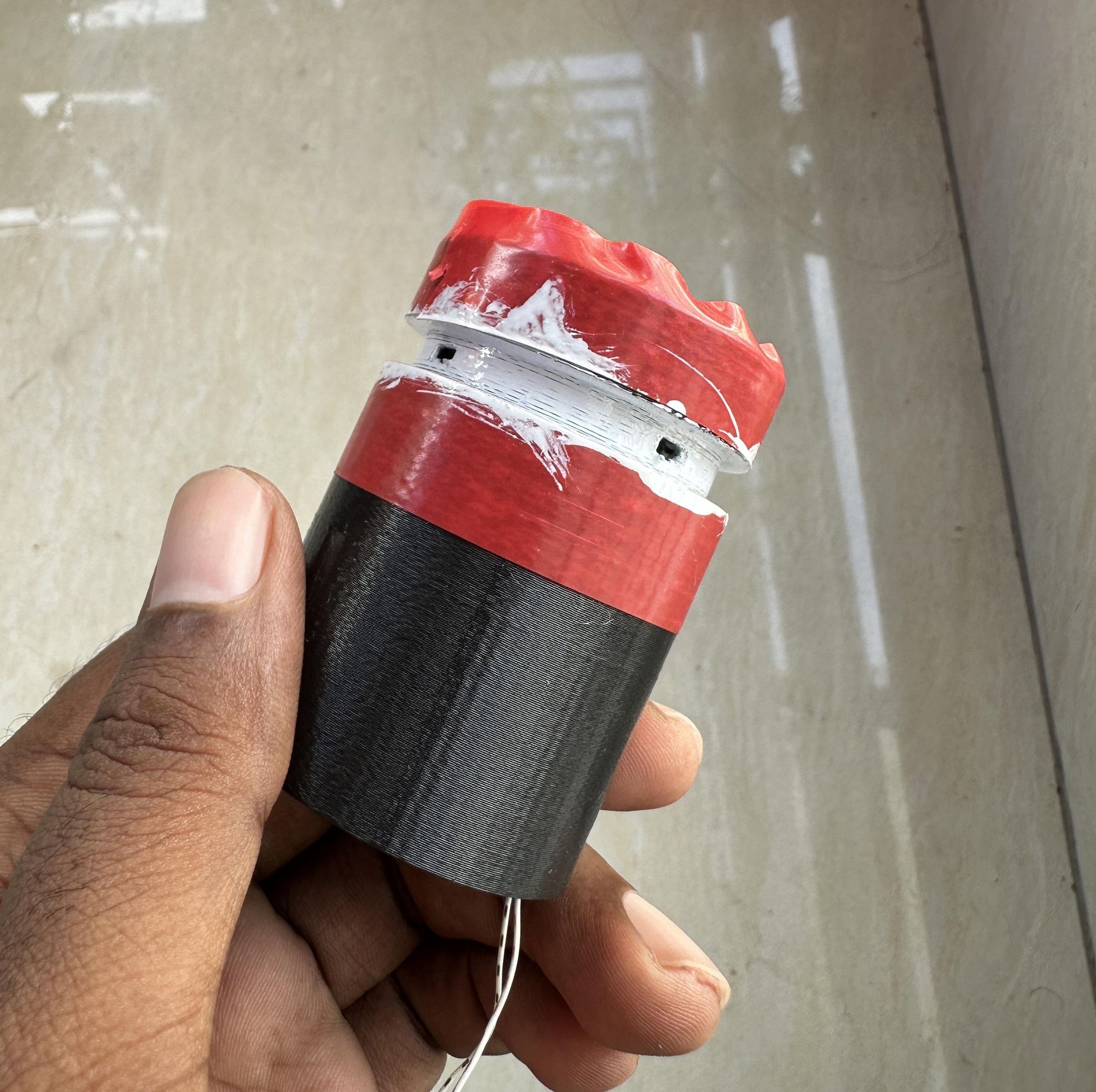
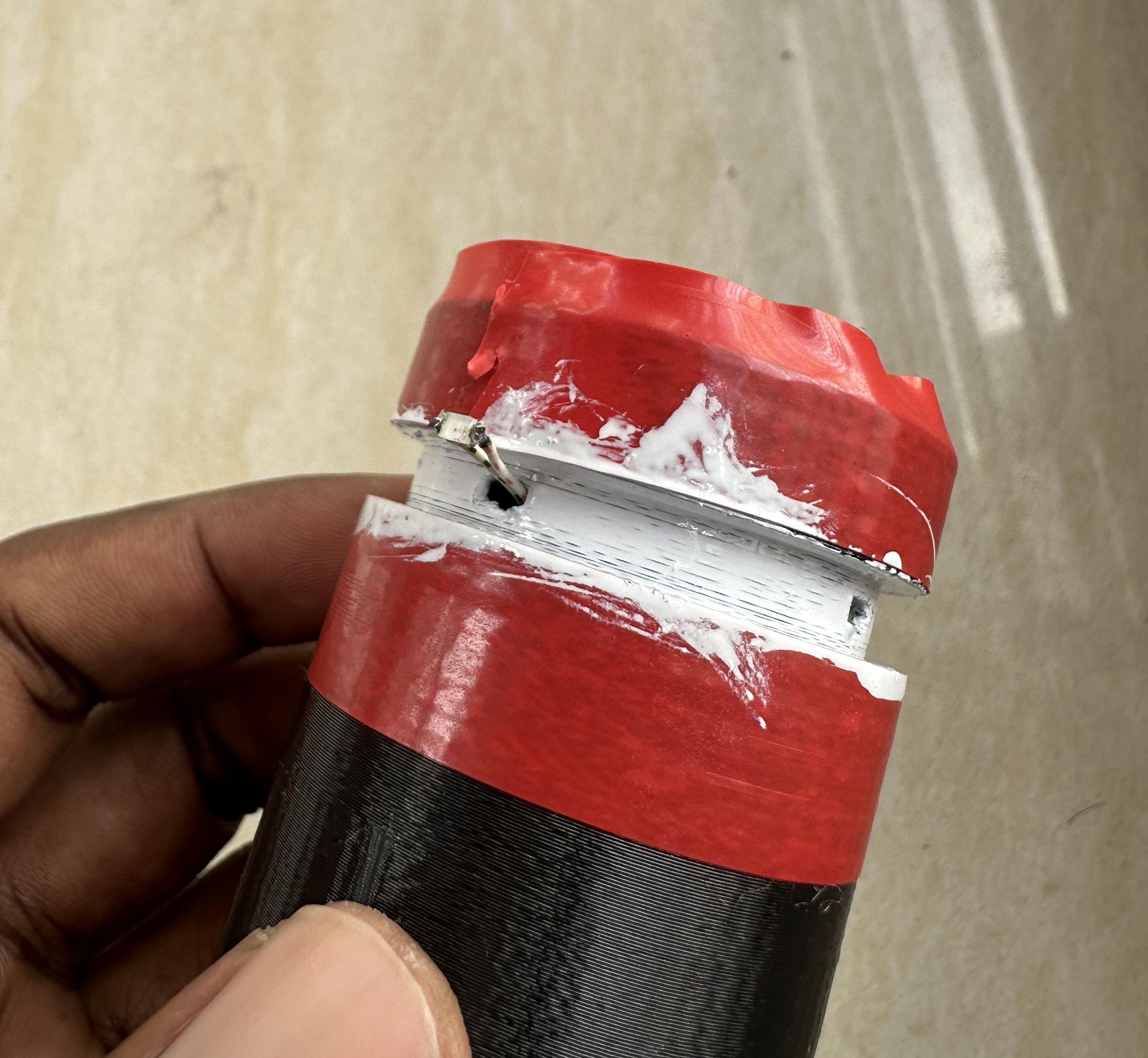
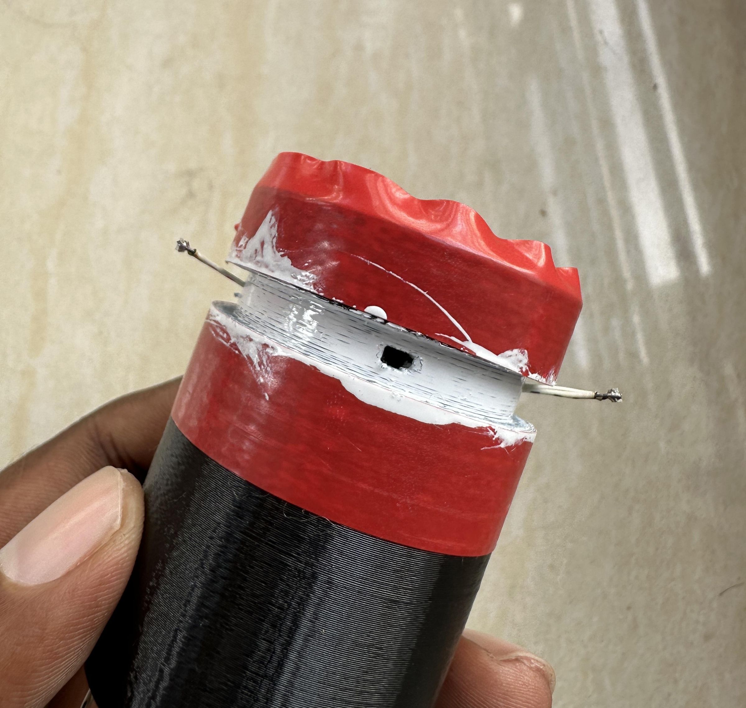
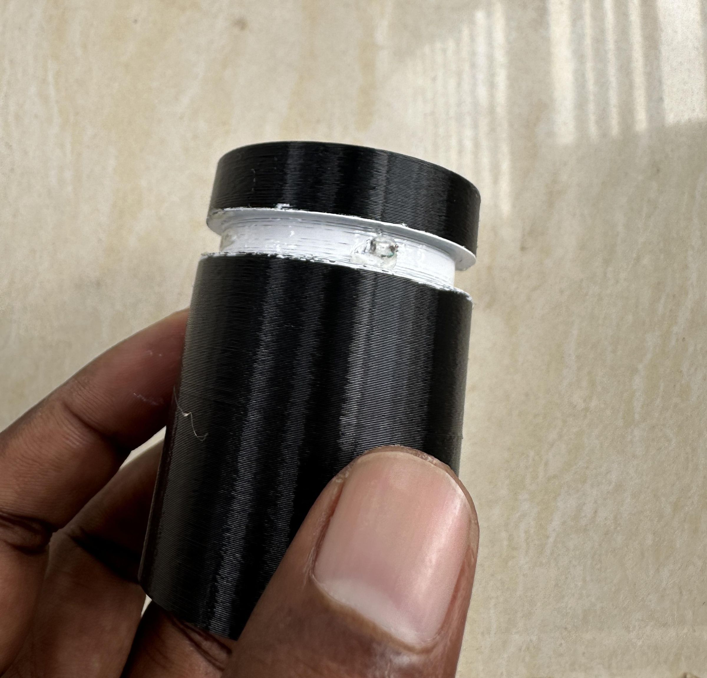
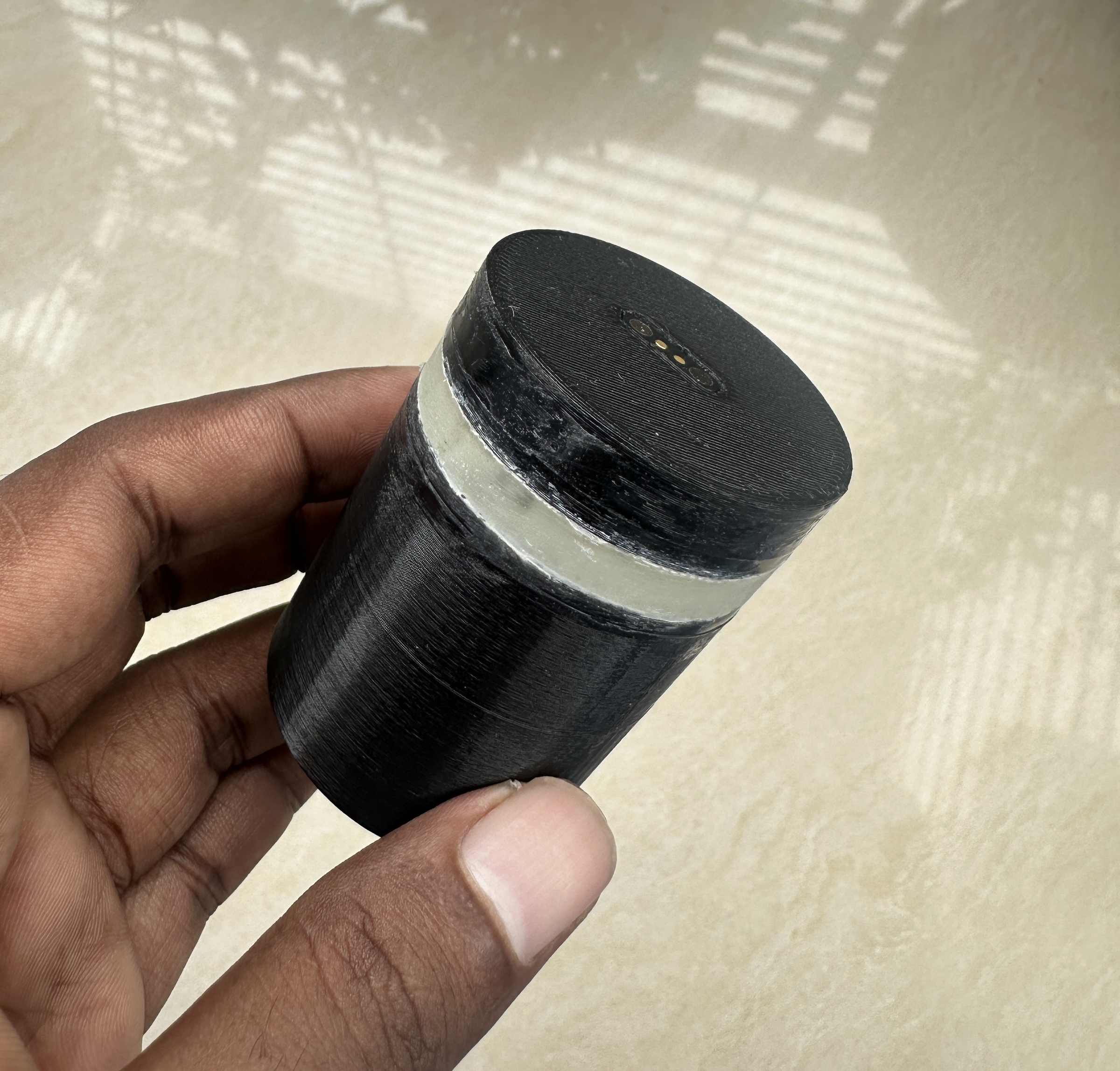
To make RainGlow look more attractive while also improving the visibility of the rain indicator, I designed the enclosure with a circular groove around the top. Instead of having the LEDs visible from only one direction, this groove creates a glowing ring that can be seen from almost any angle.
The process is simple:
Prepare the Light Ring
- The 3D-printed enclosure includes a circular channel around its upper section. Small holes were also designed to hold the two LEDs securely in place.
Apply a Reflective Coating
- Before installing the LEDs, I painted the inside of the circular groove with white paint. The white surface reflects the LED light throughout the ring, producing a brighter and more uniform glow.
Install the LEDs
- Next, I inserted the two LEDs into their mounting holes, making sure they were aligned with the circular channel. This allows the light from both LEDs to spread evenly around the ring.
Fill with Epoxy Resin
- After confirming everything worked correctly, I filled the circular groove with clear epoxy resin. The epoxy has two important functions:
- It protects the LEDs from dust, moisture, and accidental damage.
- It acts as a light diffuser, transforming the individual LED points into a smooth, continuous glowing ring.
Attach the Enclosure
- Once the epoxy had fully cured, I mounted the completed 3D-printed enclosure onto the umbrella handle. The result is a clean, modern-looking rain indicator that blends into the umbrella while remaining easy to notice.
The finished glowing ring is bright enough to catch your attention before you leave home, yet subtle enough to complement the appearance of the umbrella. The diffused light also gives RainGlow a much more polished and professional look than exposing the LEDs directly.
Tip: Allow the epoxy resin to cure completely according to the manufacturer's instructions before handling or assembling the enclosure. This ensures maximum clarity, strength, and durability.
This glowing ring became one of my favorite parts of the project—it not only protects the electronics but also gives RainGlow a distinctive, premium appearance.
Programming & Testing
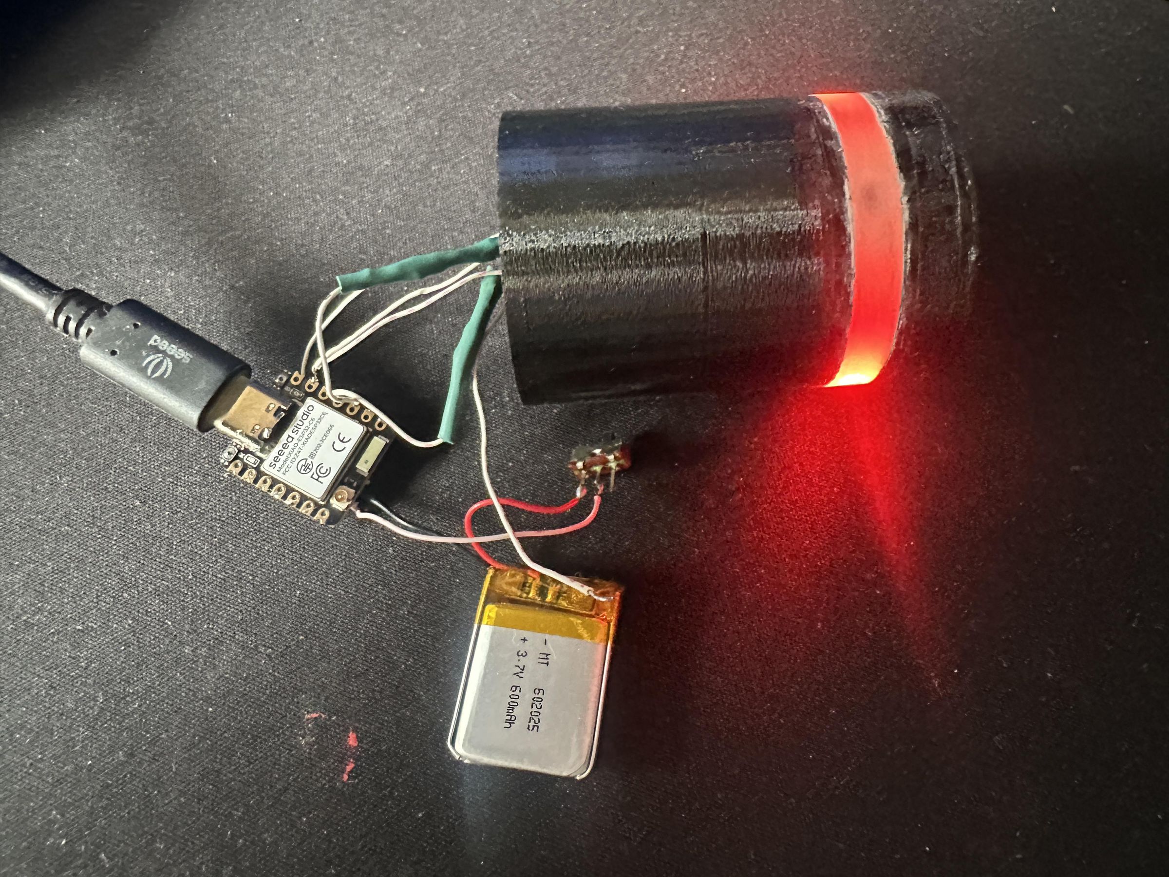
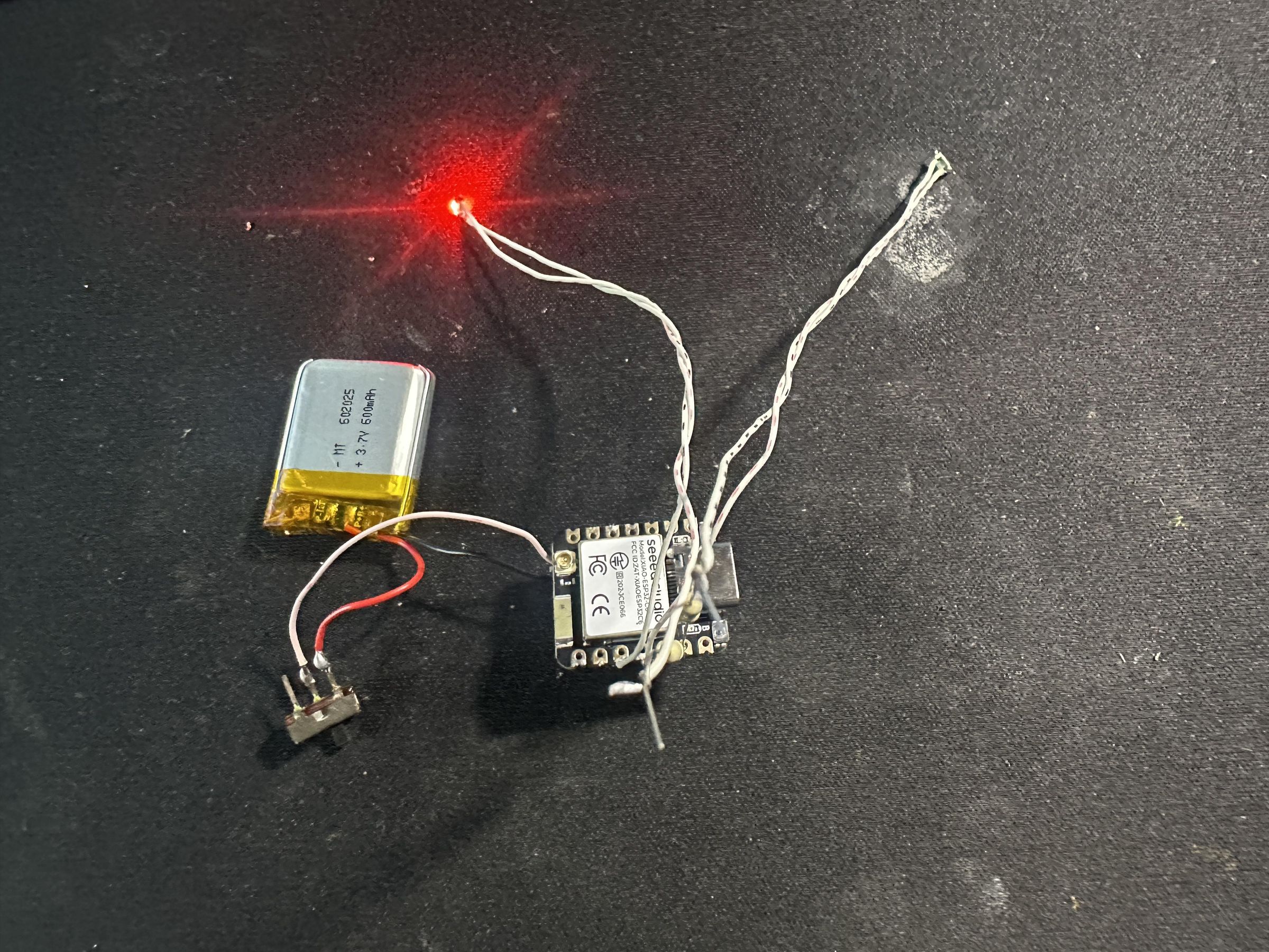
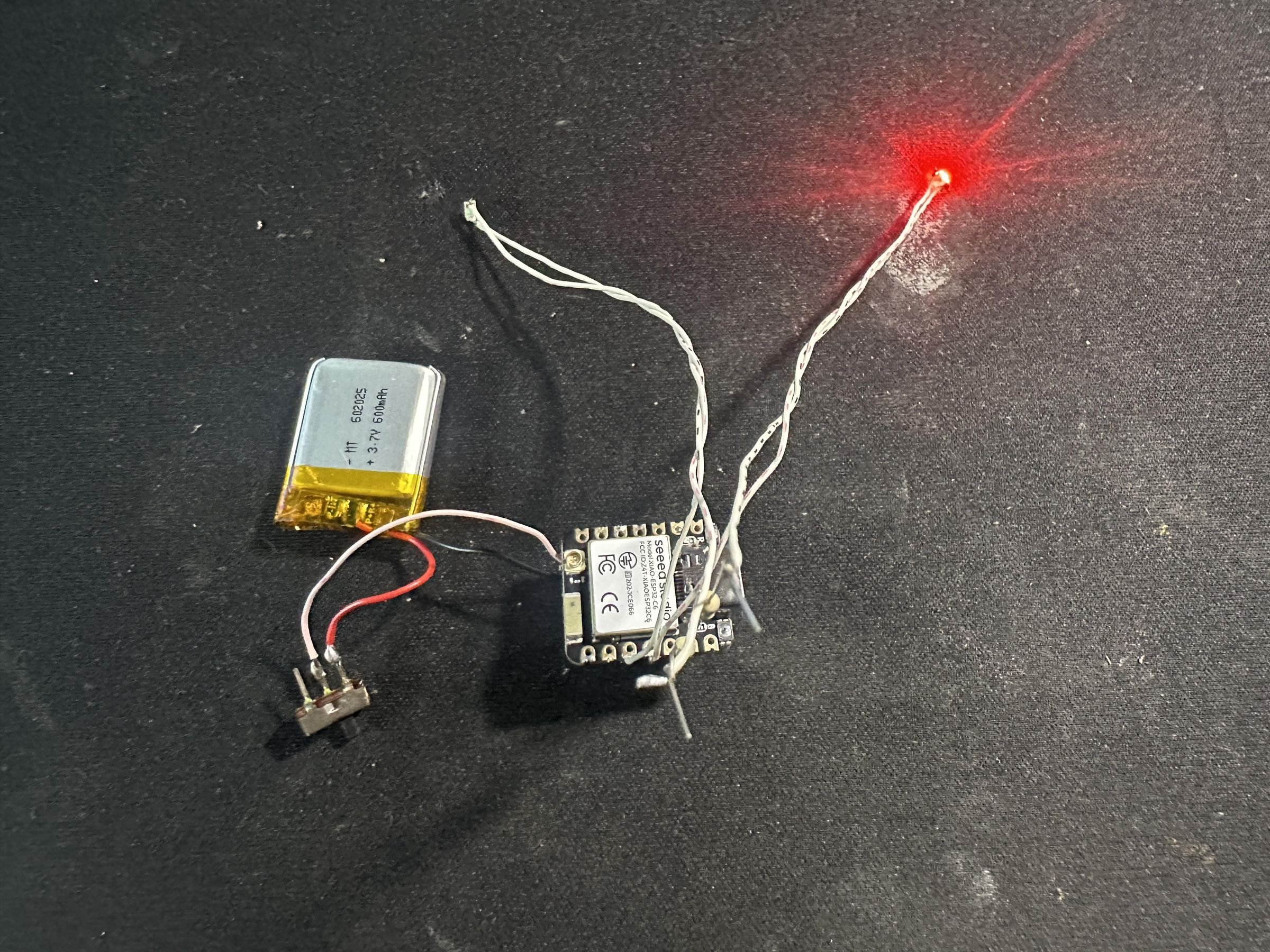
The IoT Rain Alert Umbrella is designed to provide a visual indication of the probability of rainfall before the user leaves home. The system is built around the Seeed XIAO ESP32-C6, which periodically connects to the internet, retrieves the latest weather forecast from the Open-Meteo Weather API, and alerts the user using two LEDs mounted in the umbrella handle.
To maximize battery life, the ESP32-C6 connects to Wi-Fi only when downloading weather information. After the forecast is received, Wi-Fi is completely disabled and the LEDs continue blinking according to the predicted probability of rain for the next 15 minutes. At the end of the indication period, the microcontroller enters deep sleep for another 15 minutes before repeating the cycle.
System Architecture
Working Principle
The ESP32-C6 remains in deep sleep most of the time to minimize energy consumption. Every 15 minutes, the device wakes up automatically using the built-in RTC timer.
After waking up, it performs the following operations:
- Initialize the GPIO and PWM peripherals.
- Connect to the configured Wi-Fi network.
- Synchronize the internal clock using an NTP server.
- Download the latest weather forecast from the Open-Meteo API.
- Extract the precipitation probability for the current hour.
- Disconnect and completely disable the Wi-Fi module to reduce power consumption.
- Blink two LEDs according to the rain probability for the next 15 minutes.
- Turn the LEDs off.
- Enter deep sleep for another 15 minutes.
This cycle repeats continuously while consuming very little energy.
Rain Probability Decision Table
Power Management Strategy
To maximize battery life, several power-saving techniques are implemented:
- Wi-Fi Duty Cycling: The Wi-Fi radio is enabled only during weather data retrieval and is immediately turned off afterward.
- PWM LED Control: The LEDs are driven using PWM to reduce their average current consumption while maintaining sufficient visibility.
- CPU Frequency Scaling: After downloading the weather data, the CPU clock frequency is reduced since only LED blinking is required.
- Deep Sleep Mode: The ESP32-C6 enters deep sleep for 15 minutes after each notification cycle, reducing power consumption to only a few microamps.
These techniques significantly extend battery life while maintaining continuous weather monitoring.
Advantages of the Design
- Low power consumption through deep sleep and Wi-Fi duty cycling.
- No API key required by using the free Open-Meteo weather service.
- Simple and intuitive visual notification using two LEDs.
- Adaptive blink frequency provides an immediate indication of rainfall probability.
- Modular firmware design allows future integration of additional features such as battery monitoring, OTA firmware updates, or a companion mobile application.
This architecture provides a reliable, energy-efficient, and user-friendly solution for reminding users to carry an umbrella whenever the likelihood of rain is high.
The full Arduino Code:
Downloads
Adding a Waterproof Magnetic Charging Port
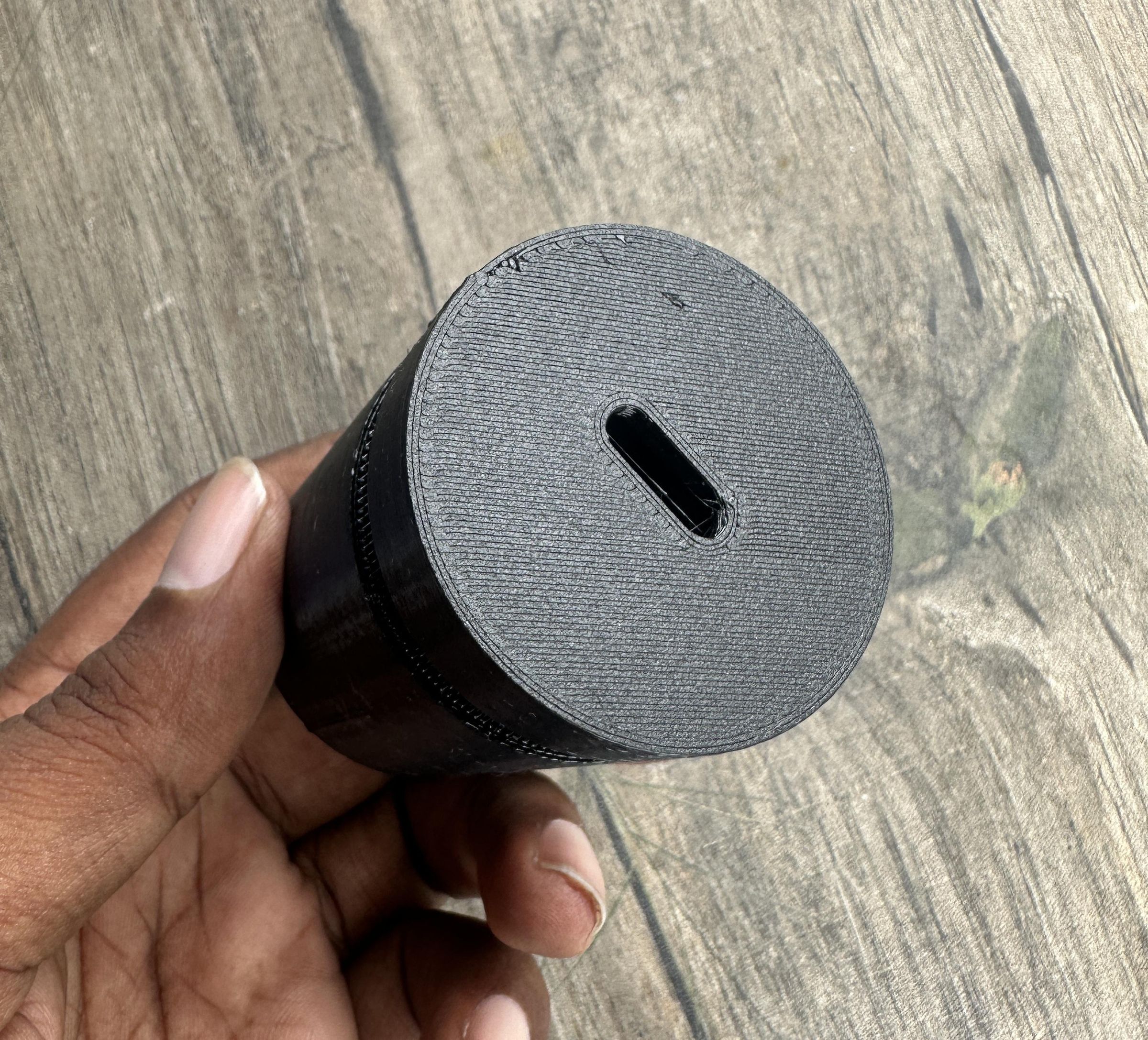
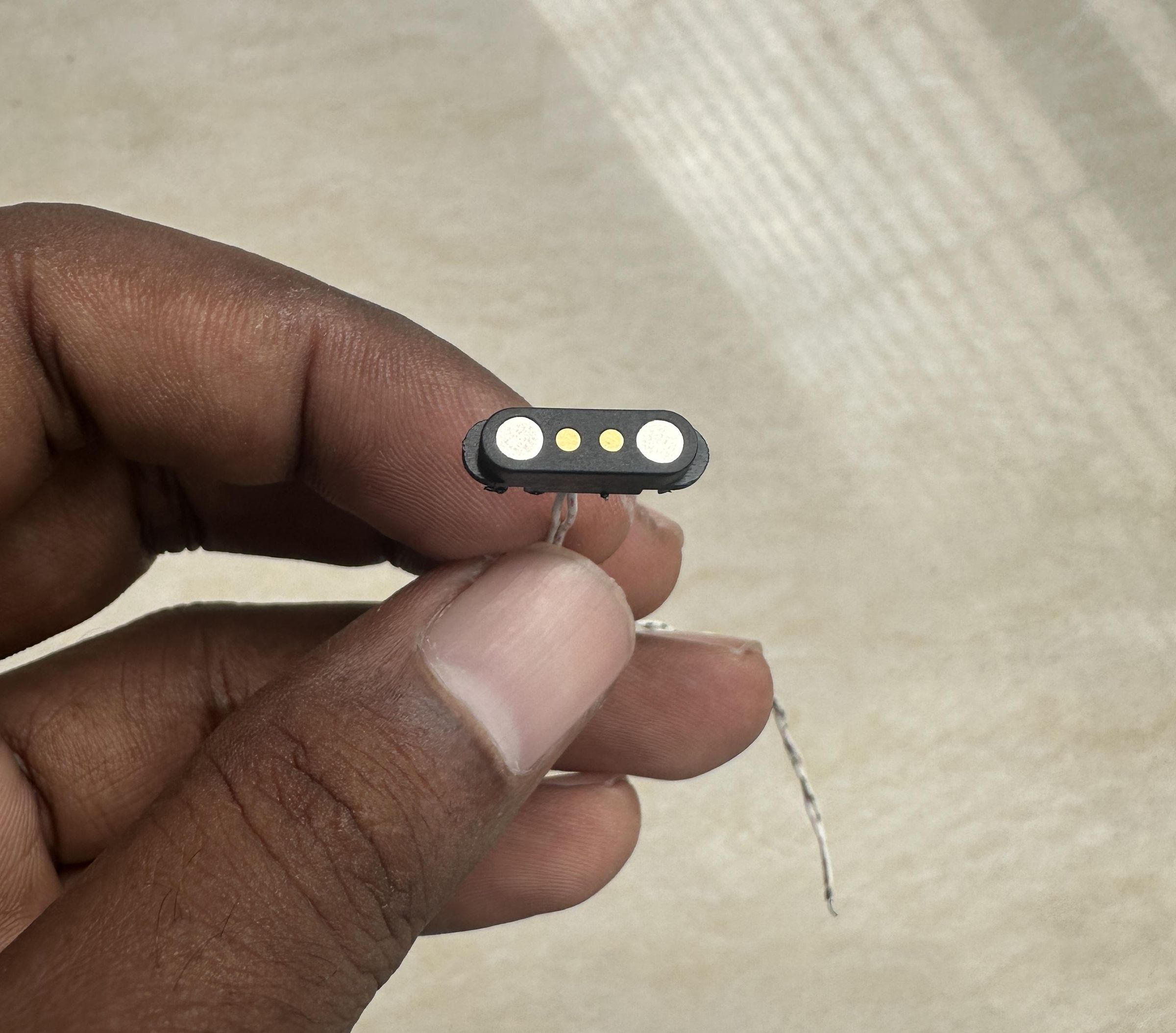
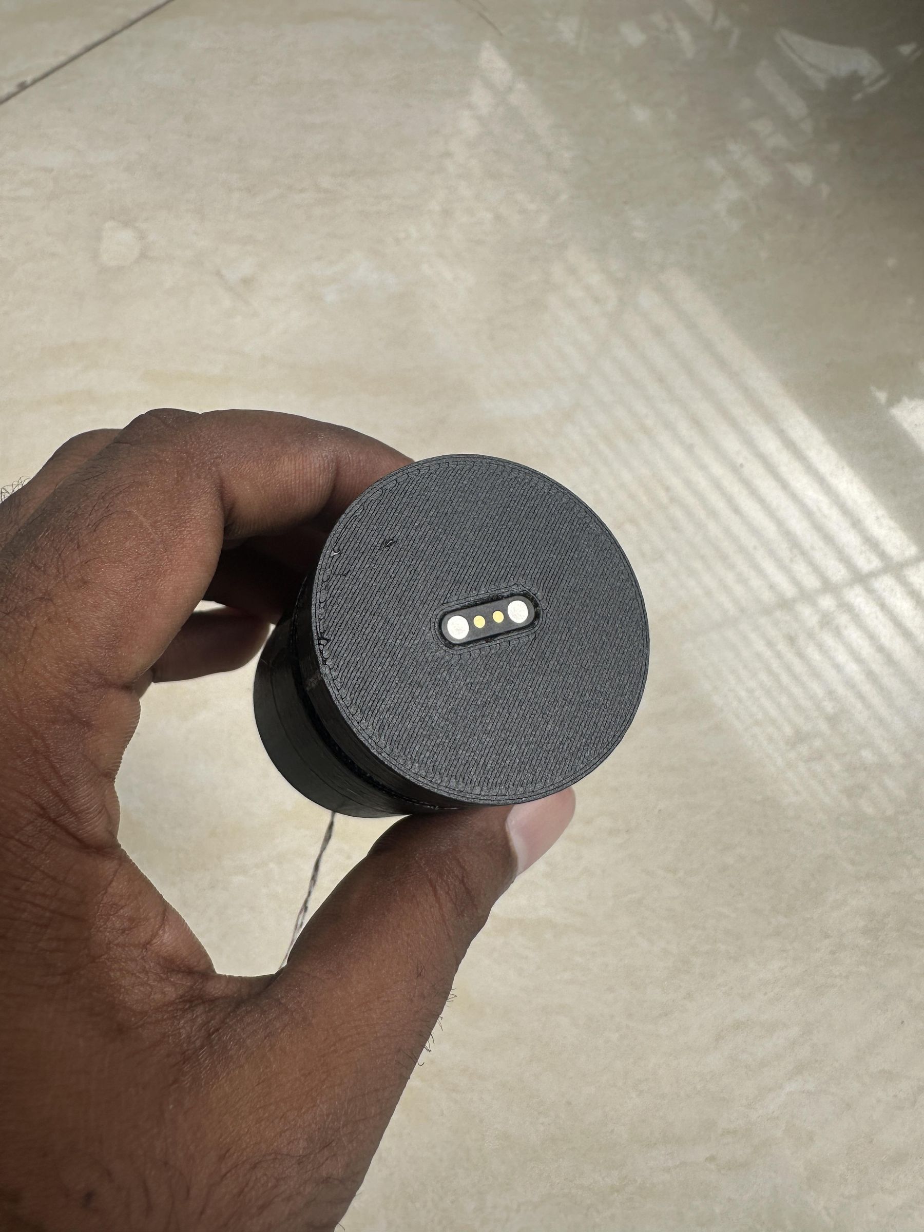
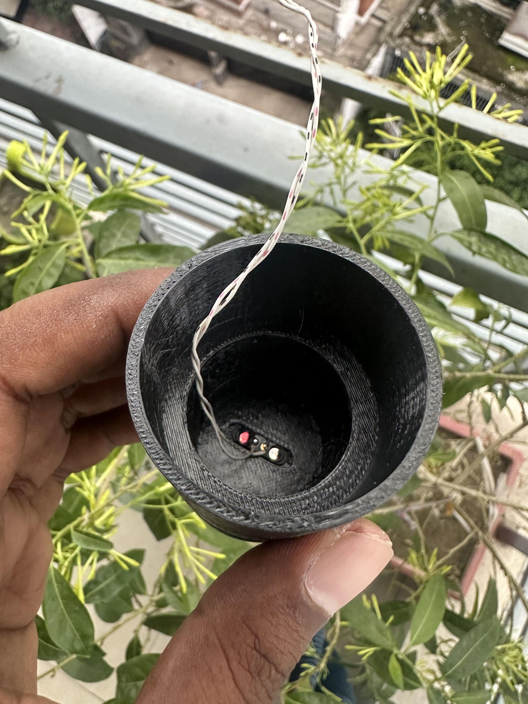
Since RainGlow is designed to be attached to an umbrella, protecting the electronics from water was one of my top priorities. At the same time, I wanted charging the battery to be quick and convenient without having to open the enclosure.
To achieve this, I used a 2-pin magnetic pogo pin connector as the charging interface.
Why a Magnetic Pogo Pin?
A magnetic pogo pin connector offers several advantages over a traditional USB connector:
- No need to open the enclosure for charging.
- Better protection against rain and moisture.
- Magnetic alignment makes charging quick and easy.
- Fewer exposed openings help maintain the clean appearance of the enclosure.
Preparing the Enclosure
During the CAD design stage, I created a rectangular opening on the bottom of the enclosure that matches the dimensions of the magnetic pogo pin connector.
After 3D printing, the connector fit neatly into this slot with its contact pins exposed on the outside, making them easily accessible for the magnetic charging cable.
Installing the Connector
Once I confirmed the connector fit properly, I inserted it into the opening from the outside of the enclosure.
To secure it permanently, I applied hot glue from the inside of the enclosure. This keeps the connector firmly in place while preventing it from moving or being pushed inward when the charging cable is attached or removed.
The electrical connections are simple:
- Positive pin → VBUS on the Seeed Studio XIAO ESP32-C6
- Ground pin → GND
Since the XIAO ESP32-C6 includes a built-in Li-Po charging circuit, connecting the pogo pins to VBUS and GND allows the battery to be recharged safely without any additional charging hardware.
The result is a compact, reliable, and water-resistant charging solution that complements the overall design of RainGlow. Simply snap the magnetic charging cable onto the pogo pins whenever the battery needs recharging—no disassembly required.
Tip: Before permanently gluing the connector, test it with the magnetic charging cable to ensure the polarity is correct. Reversing the positive and ground connections may prevent charging or damage the circuit.
This simple addition makes the project much more practical for everyday use while helping to keep the enclosure protected from the elements.
Battery Lifetime Calculation
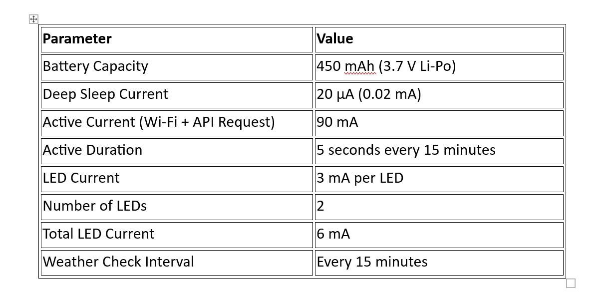
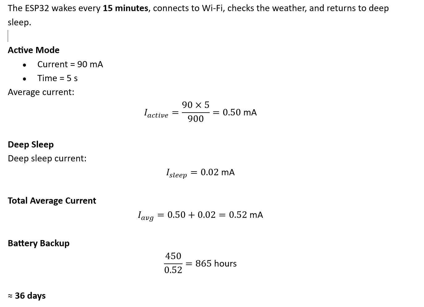
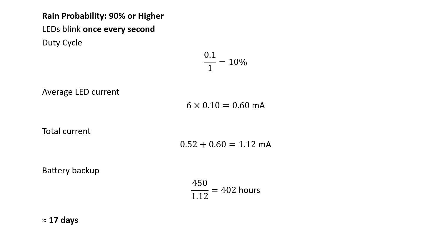
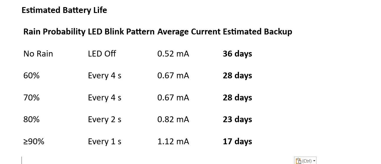
Below is a practical battery life estimation for your RainGlow project. Since the exact current depends on Wi-Fi signal strength and firmware, I've used realistic values for the Seeed Studio XIAO ESP32-C6.

Base System Consumption (No Rain)


Final Assembly
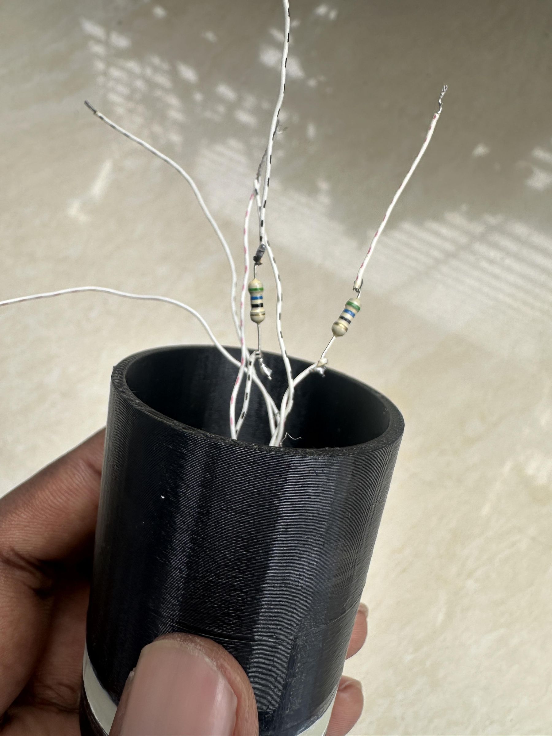
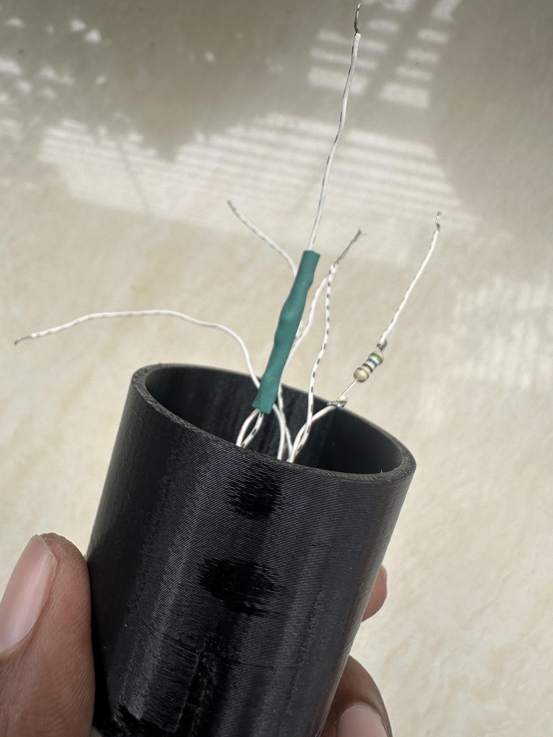
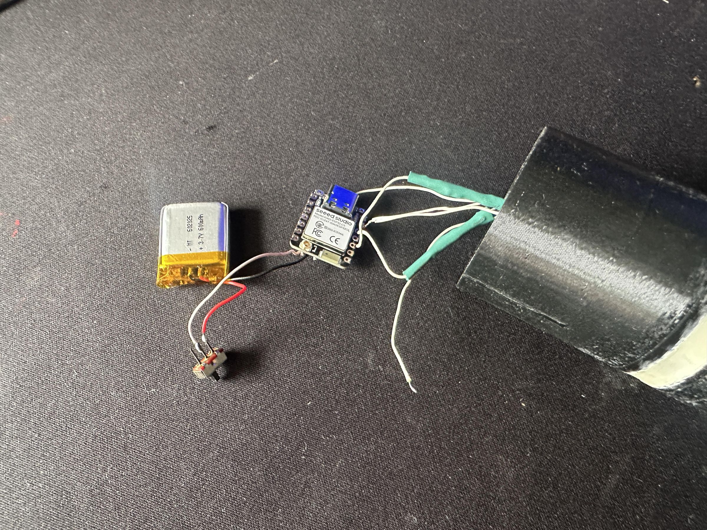
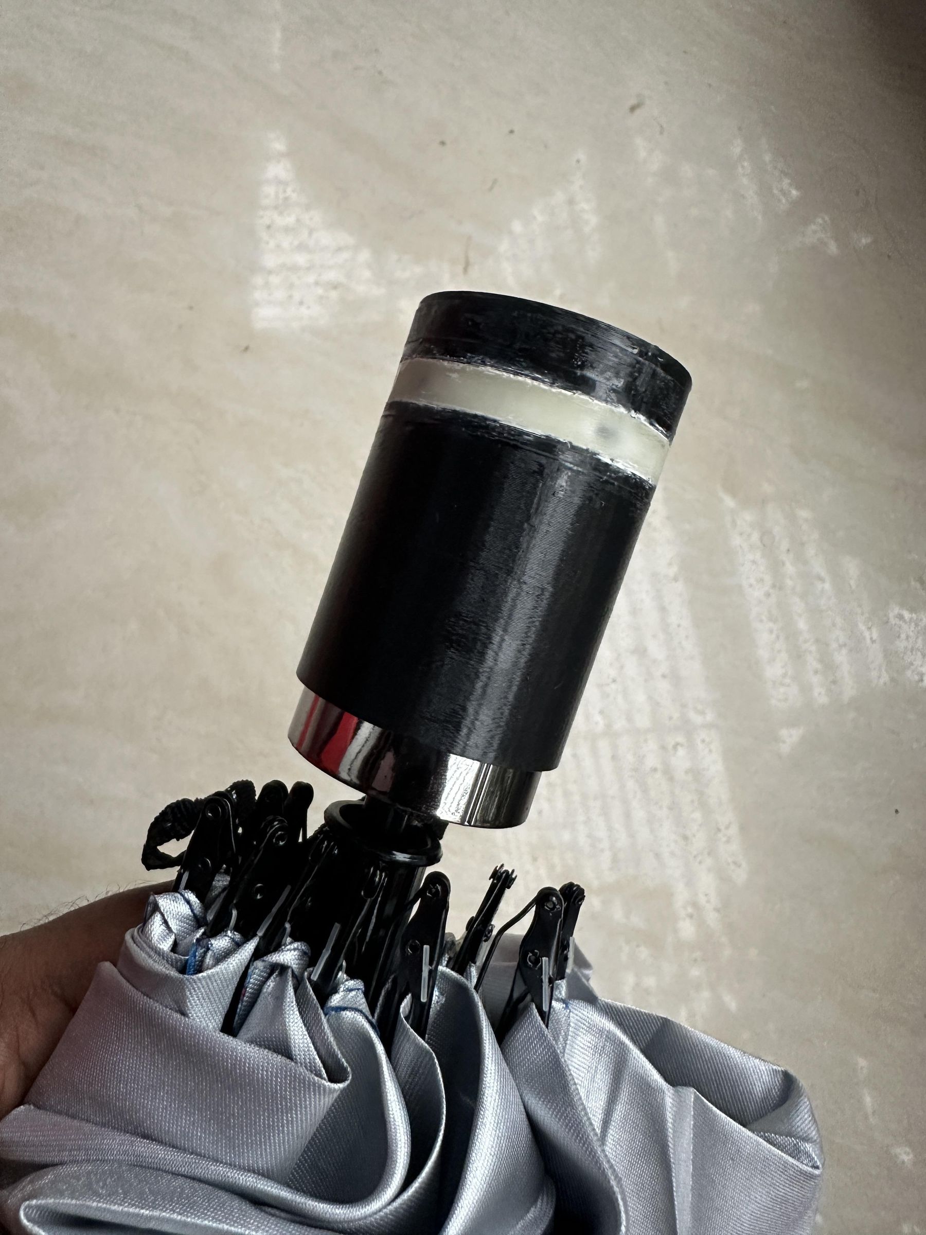
With all of the individual parts prepared, it was time to assemble everything inside the 3D-printed enclosure.
Preparing the LED Assembly
I first soldered a 100 Ω resistor in series with each LED to limit the current and protect both the LEDs and the ESP32-C6 GPIO pins. After soldering, I covered all exposed connections with heat-shrink tubing to provide electrical insulation and prevent accidental short circuits inside the enclosure.
Next, I soldered the LED wires to the D9 and D10 pins of the Seeed Studio XIAO ESP32-C6, along with the common ground connection.
Installing the Electronics
Since the enclosure is very compact, I chose not to use a PCB. Instead, all of the components were connected using direct wiring, which saved space and simplified the build.
I carefully arranged the components inside the enclosure in the following order:
- Seeed Studio XIAO ESP32-C6
- Li-Po battery
- Sliding power switch
- LED wiring
- Magnetic pogo pin charging connector
Before closing the enclosure, I powered the circuit to verify that both LEDs, the switch, and the charging connector were functioning correctly.
Securing the Components
Without a PCB, the components could move around inside the enclosure during everyday use. To prevent this, I placed small pieces of cotton between the components. The cotton acts as a soft spacer, keeping each part securely in place while also preventing the battery, wires, and circuit board from rubbing against each other.
This simple solution helps absorb small vibrations and keeps the electronics organized inside the enclosure without adding extra weight or requiring custom mounting brackets.
After arranging all of the components, I carefully tucked the wires into the remaining space and closed the enclosure. The result is a compact, lightweight, and neatly assembled smart umbrella attachment.
Tip: Before sealing the enclosure, double-check all solder joints and test the circuit one final time. Fixing a wiring issue is much easier before the enclosure is fully assembled.
The final assembly is surprisingly compact, proving that a practical IoT device can be built with only a few components and thoughtful internal layout.