Rotational Jet-Impingement Can Cooler
431 Views, 2 Favorites, 0 Comments
Rotational Jet-Impingement Can Cooler
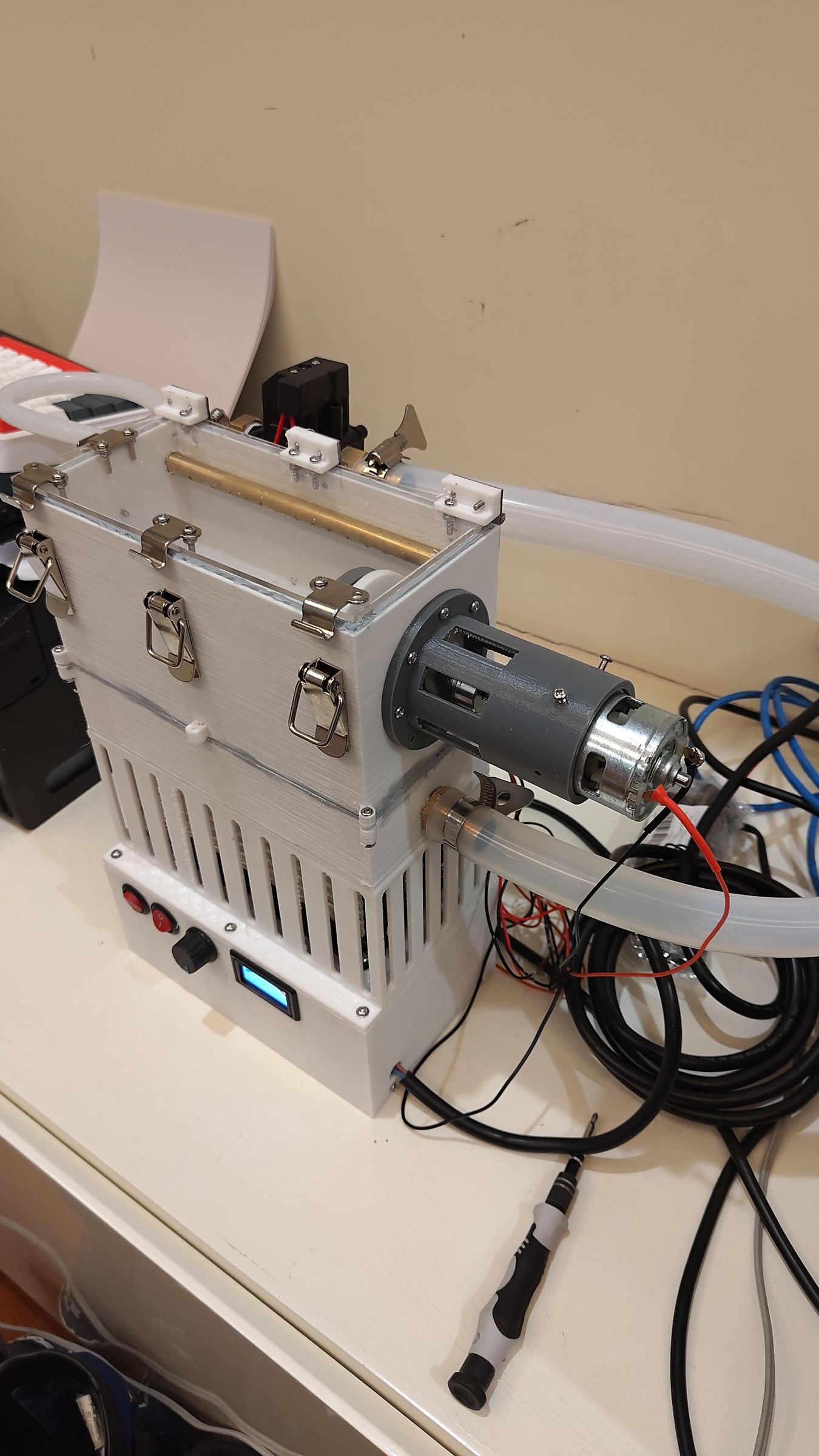
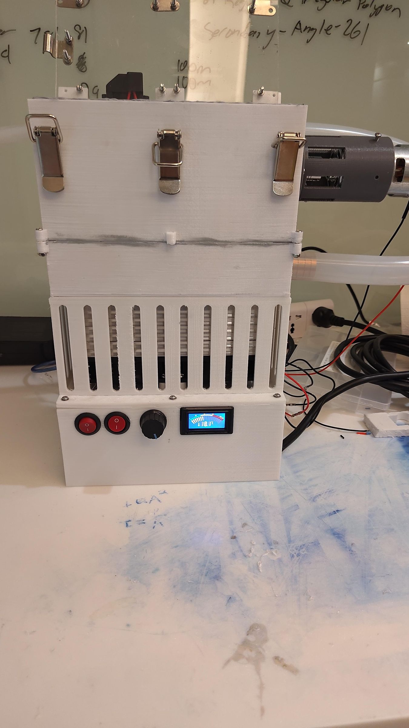
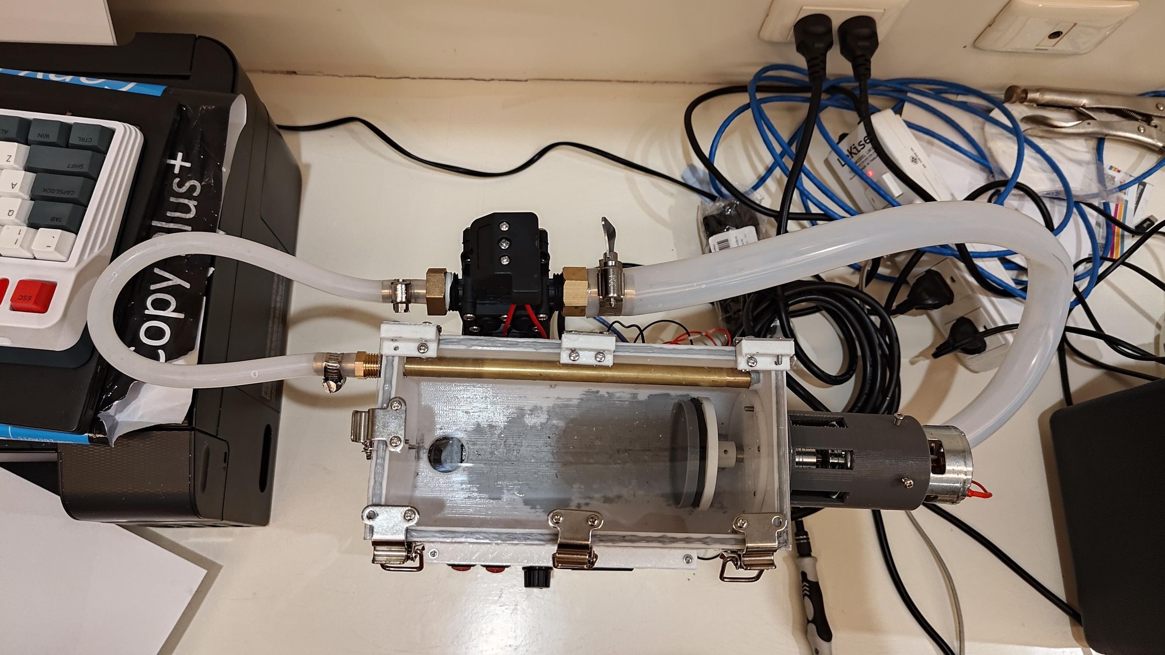
If you've ever looked up rapid beverage cooling gadgets, you may have seen devices that spin a can inside an ice bath. While spinning a can to mix the liquid inside is a great trick to rapidly cool the drink. It only solves half of the thermodynamic problem. The outer surface of the can still gets trapped in a stagnant, slow-moving thermal bottleneck. So if we were to improve on this bottleneck, how much faster could we cool a beverage?
So the purpose of this project was to take what has been done before and improve upon it even further, instead of spinning a can in static ice water. This design introduces two new tricks for cooling the cans. Those are high-velocity water jet impingement combined with dual-axial rotation!
Supplies
Materials:
- 3D printing filament
- 2mm aluminium plate
- Epoxy
- Gasket maker
- Optional: PU foam spray
- 19mm ID silicone tube
- 8mm ID silicone tube
- 10mm OD 8mm ID tube
- Thermal Paste
- 8mm rod
- Solder
Hardware:
- M3 screws
- M4 screws (for pc fan)
- Latches
- Hose clamp (buy for specific size of tubing)
- 8x22x7 mm Bearings
- Hinges
- 8-5mm coupling
- Velcro
- 1/2 female to 8mm barb brass fitting
- 1/4 male to 8mm barb brass fitting
- 1/2 female to 19mm barb brass fitting
- 1/2 male to 19mm barb brass fitting
*for brass fittings either use NPT or BSP (I chose to use BSP)
Electronics:
- Arduino Nano
- 775 DC motor
- Optional: Ferrule
- LM2596 Buck converter
- Jumper Wires
- KCD1-105 on-off switch
- BTS7960 PWM Drive
- Peltier Module
- GP-1633 plug
- 12V Diaphram pump
- PWM DC Motor Driver 20A
- 12V power supply (atleast 20A rating)
- 5-25V Digital LCD thermometer
Tools:
- 3d printer
- Screw Drivers
- Soldering Iron
Theory
TL;DR
More Turbulent = Faster Cooling
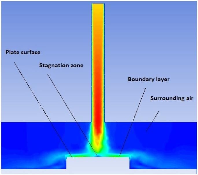
Jet Impingement: Blast away the external warm-water layer (blanket) with high-pressure streams
Direction Flipping: Reversing the direction of spin every few seconds uses the liquid's own inertia against it. As the can wall slams into the fluid, it generates massive forces that force the warm center to smack into the freezing walls of the can.
Deeper Dive:
To cool a drink down fast, the heat has to move out of the beverage. It must pass through the beverage and the aluminium can into the cooling water. During this process, the heat usually gets trapped by two bottlenecks:
- External Bottleneck: Thin layer of warmed water which clings to the outside of can
- Internal Bottleneck: Liquid inside the can right next to the aluminium wall cools quickly, but becomes stagnant. Acting as an insulating barrier, trapping the heat inside the middle of the drink
Solving External Bottleneck:
Jet impingement cooling is where high-pressure streams of water are sprayed directly onto the can. Causing fluid movement outside to transition from laminar to turbulent. This high-pressure stream completely destroys the layer of warmed water (blanket). Replacing it with a continuous turbulent thin layer of water that strips heat away from the aluminium surface at a greater rate.
Solving Internal Bottleneck:
In traditional rapid drink coolers that spin the can in one direction. The liquid mixes but only for the first few seconds. As soon as the liquid inside catches up to the speed of the spinning can. And once again the liquid and the can are spinning together at the same speed, and mixing stops. Where heat goes back to being concentrated at the center.
However, by reversing the direction of the rotation every few seconds. This causes the aluminium can walls to change direction while the liquid inside still wants to keep spinning forward due to its inertia. Therefore, this causes the can walls to forcefully slam into the liquid. This sudden, violent change in direction creates a lot of turbulence, preventing any stagnant layers from forming. It continuously forces warm liquid from the core to crash directly into the cold can walls.
CAD
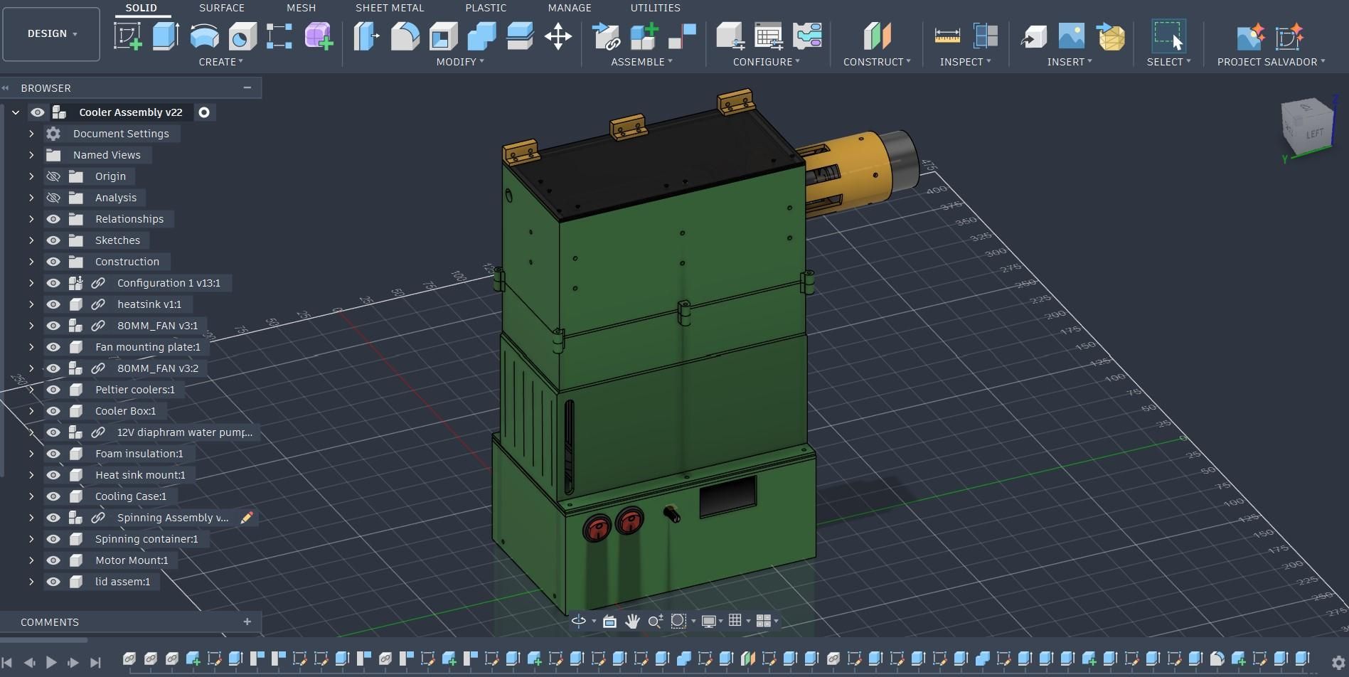
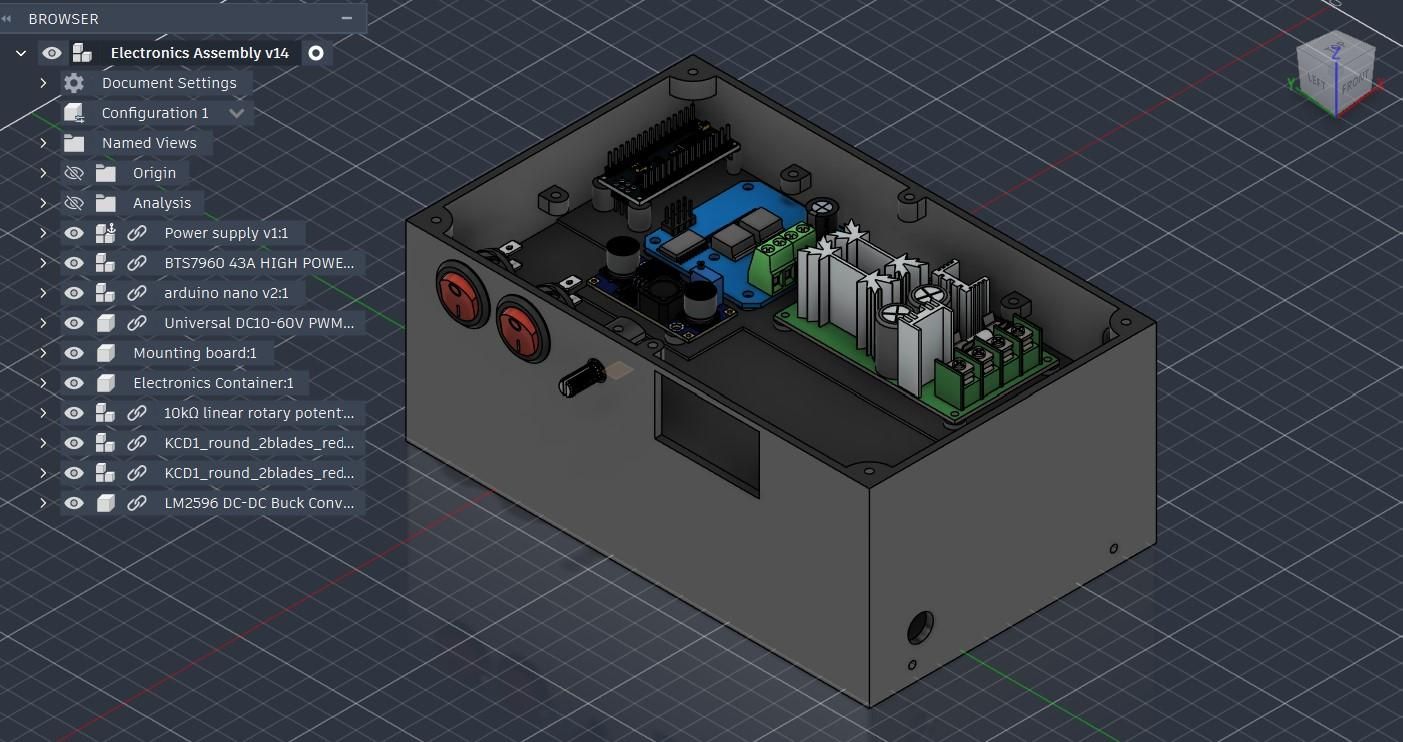
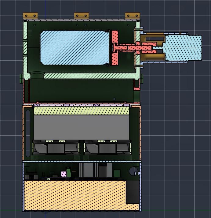
Using CAD for this project was extremely useful, as I was able to fit everything in the right place without cramming, making all the components super organized. It was especially useful for electronics, as I was able to design a mounting board for them. The CAD program used for this was Fusion 360.
3D Printing
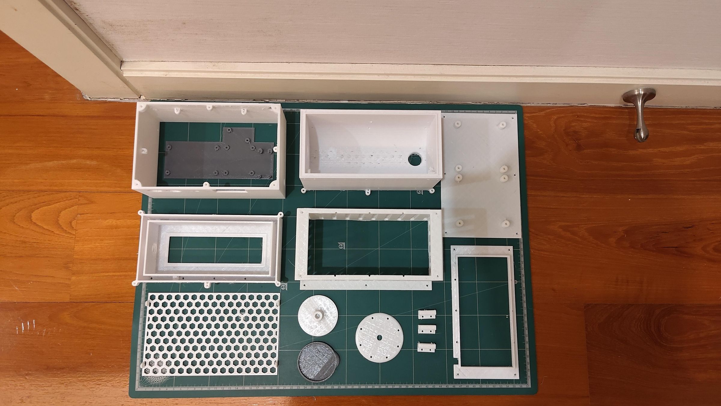
Please keep in mind that the design of the components are made especially for my 3D printer which is considered very outdated. So for example it was designed with the least amount of overhangs needed. Hence, if you have a modern 3D printer, your printer should have absolutely no issue printing these parts. 👍
Electronics
.png)
Assembling Electronic Box
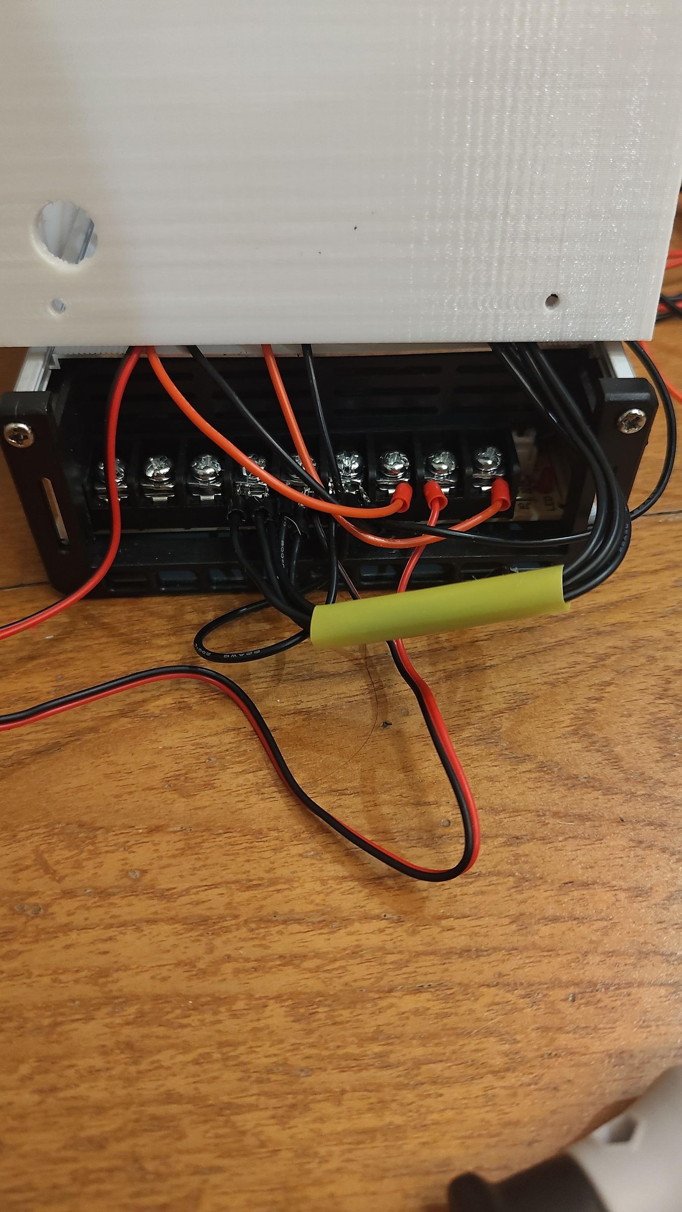
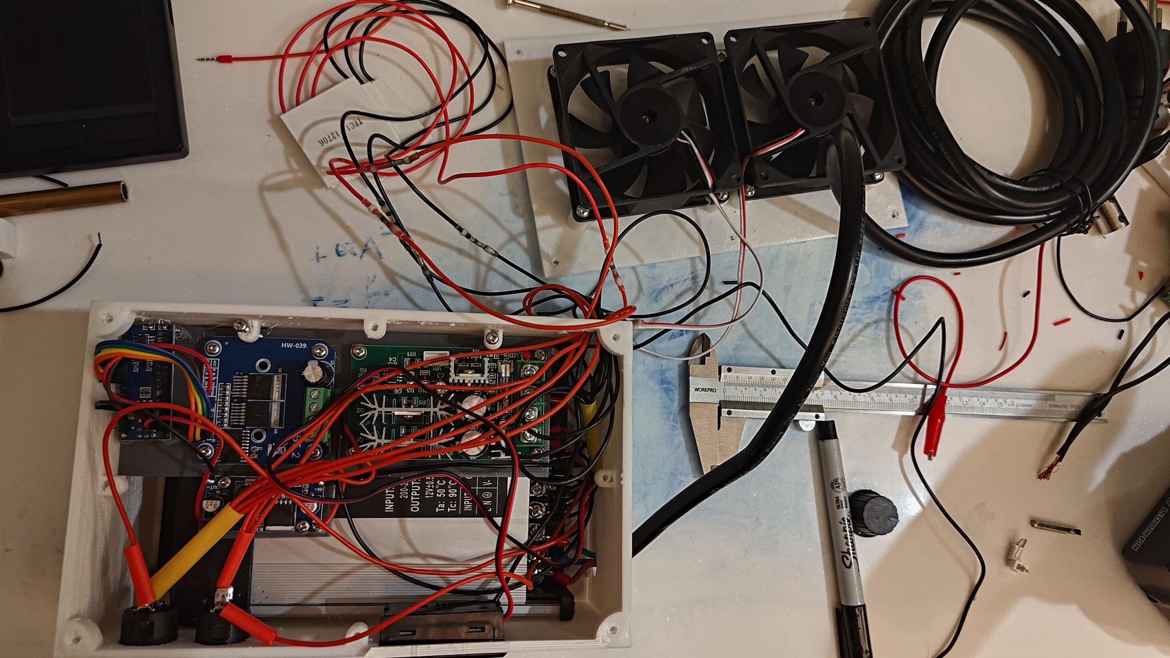
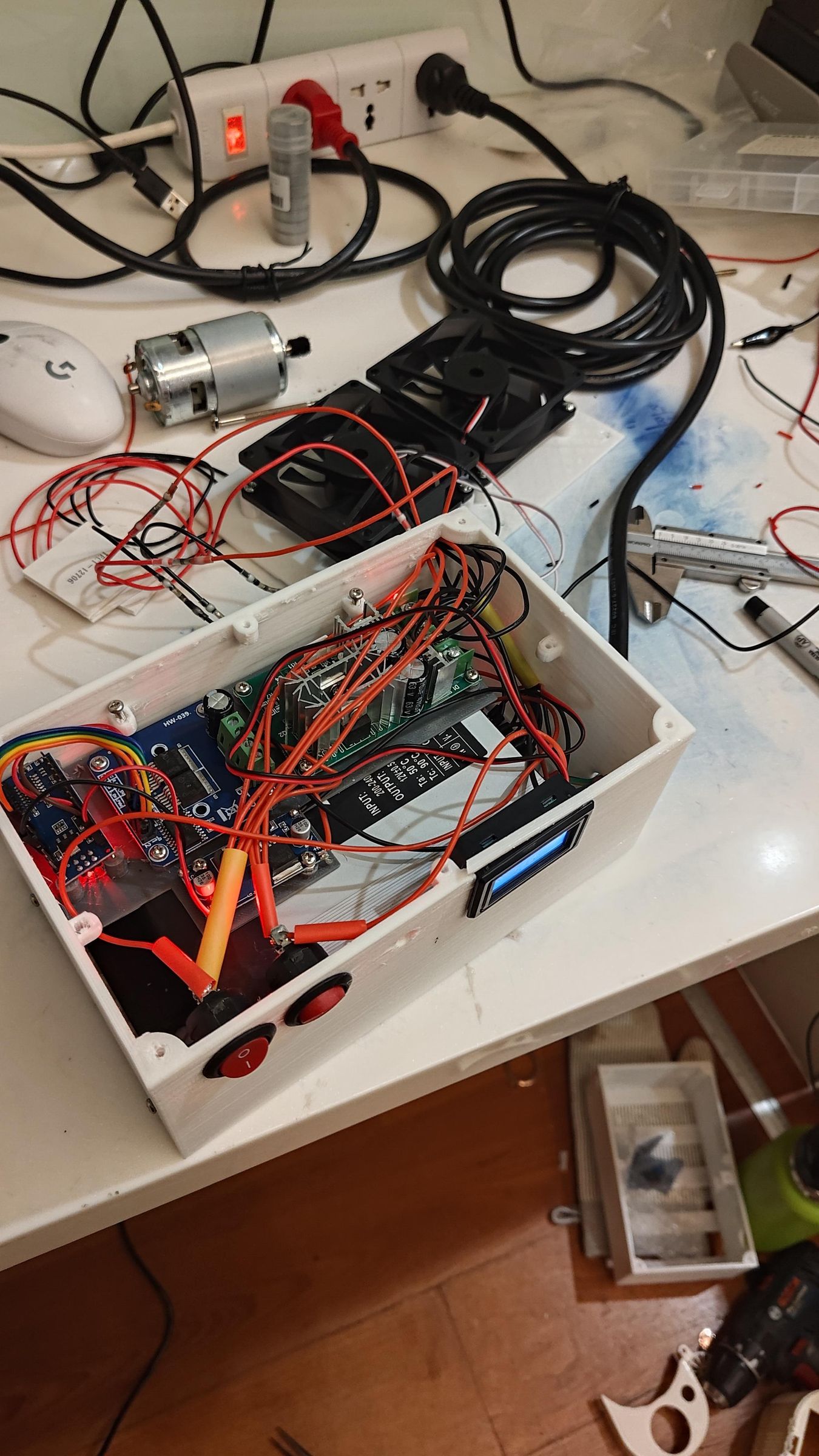
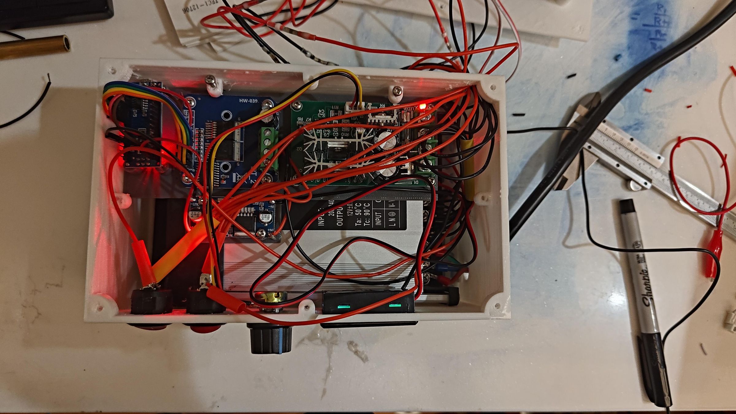
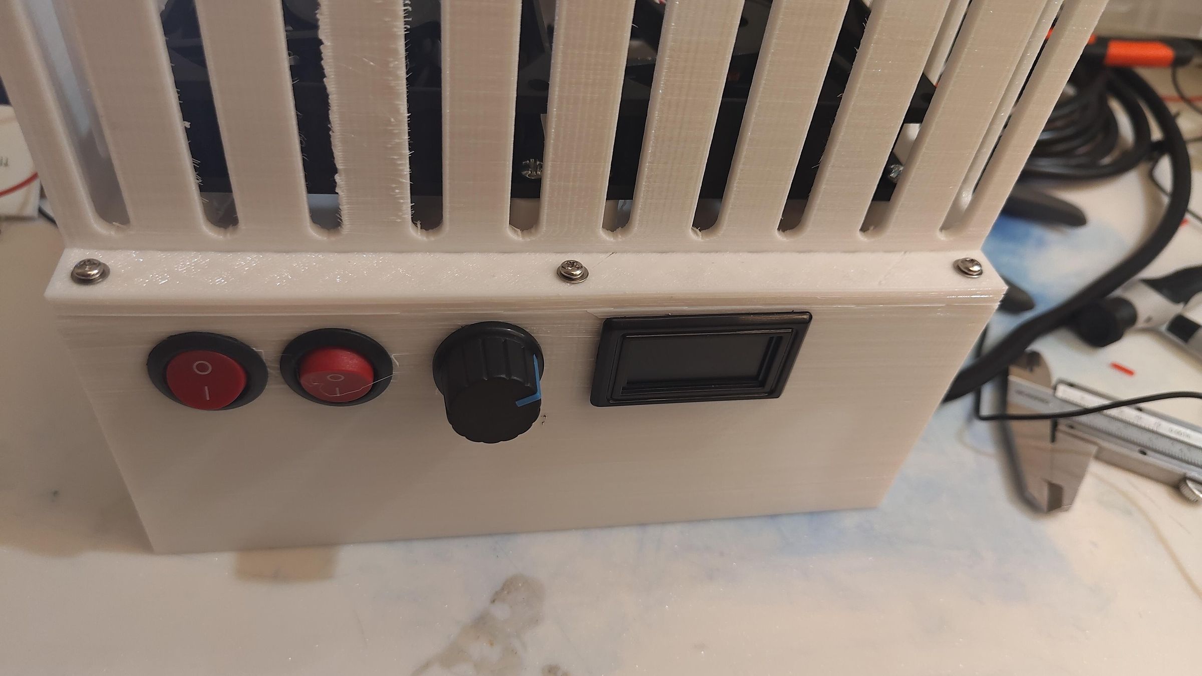
On the control panel, you should see two on-off switches, a dial, and a screen:
Left Switch: Turns the cooling system on or off. These are 2 PC fans and 3 Peltier Modules. This switch is usually left on so that it continuously cools the water. So that the
Right Switch: Turns the pump and the spinning motor on, causing high-velocity streams of water to be sprayed onto the surface of the can. At the same time, the can is continuously rotated in opposite directions every few seconds.
The Dial (Potentiometer): Controls the power of the pump, which controls the strength of the water streams being sprayed at the can. This was put here for me to test out how changing the velocity of the water streams would affect the cooling performance.
The screen: This is just an LCD screen connected to a thermometer displaying the temperature of the water inside the cooling box.
sorry for my wire/cable management - I have very little experience handling this amount of wires.
:/
Mounting PC Fans
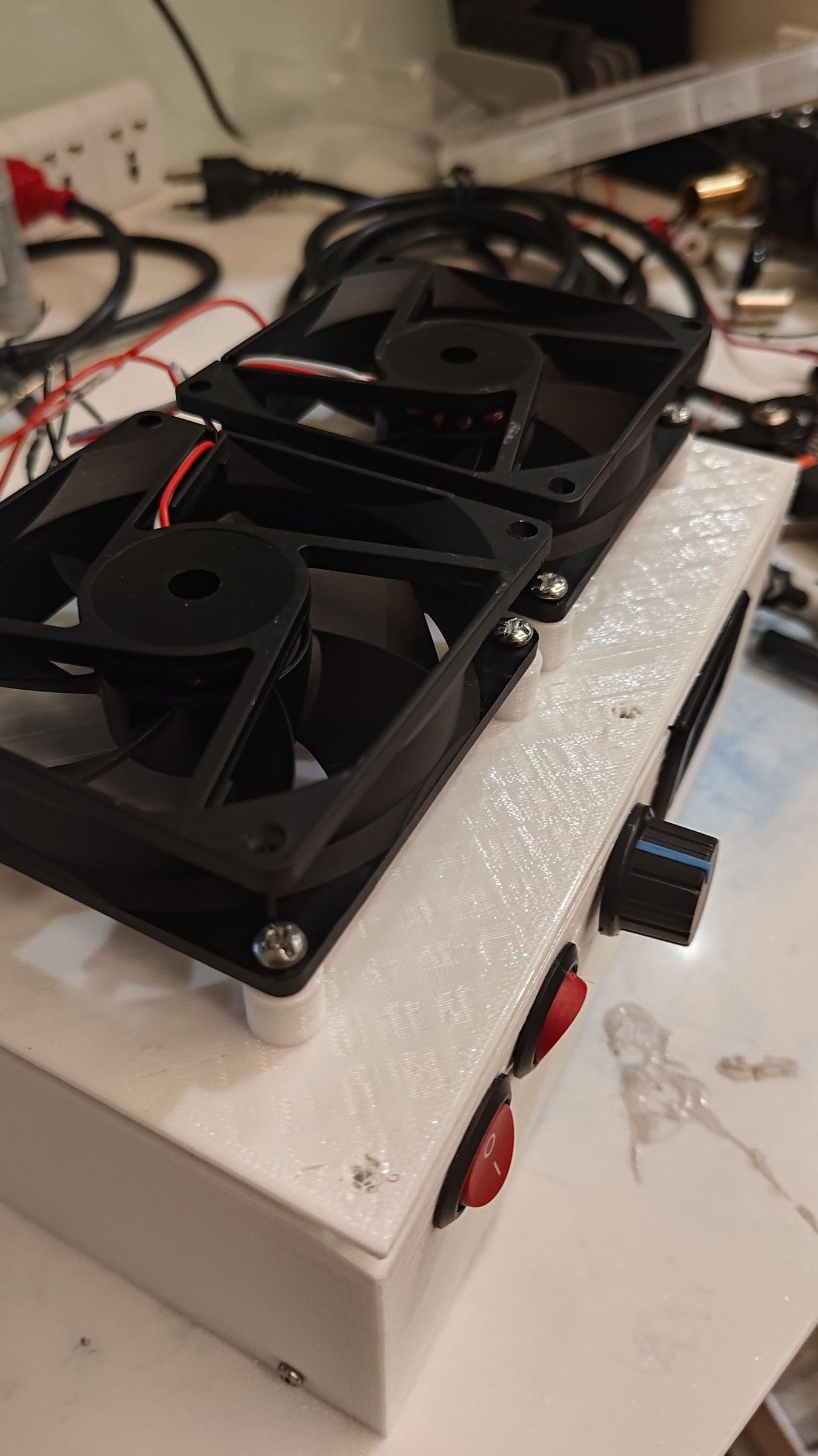
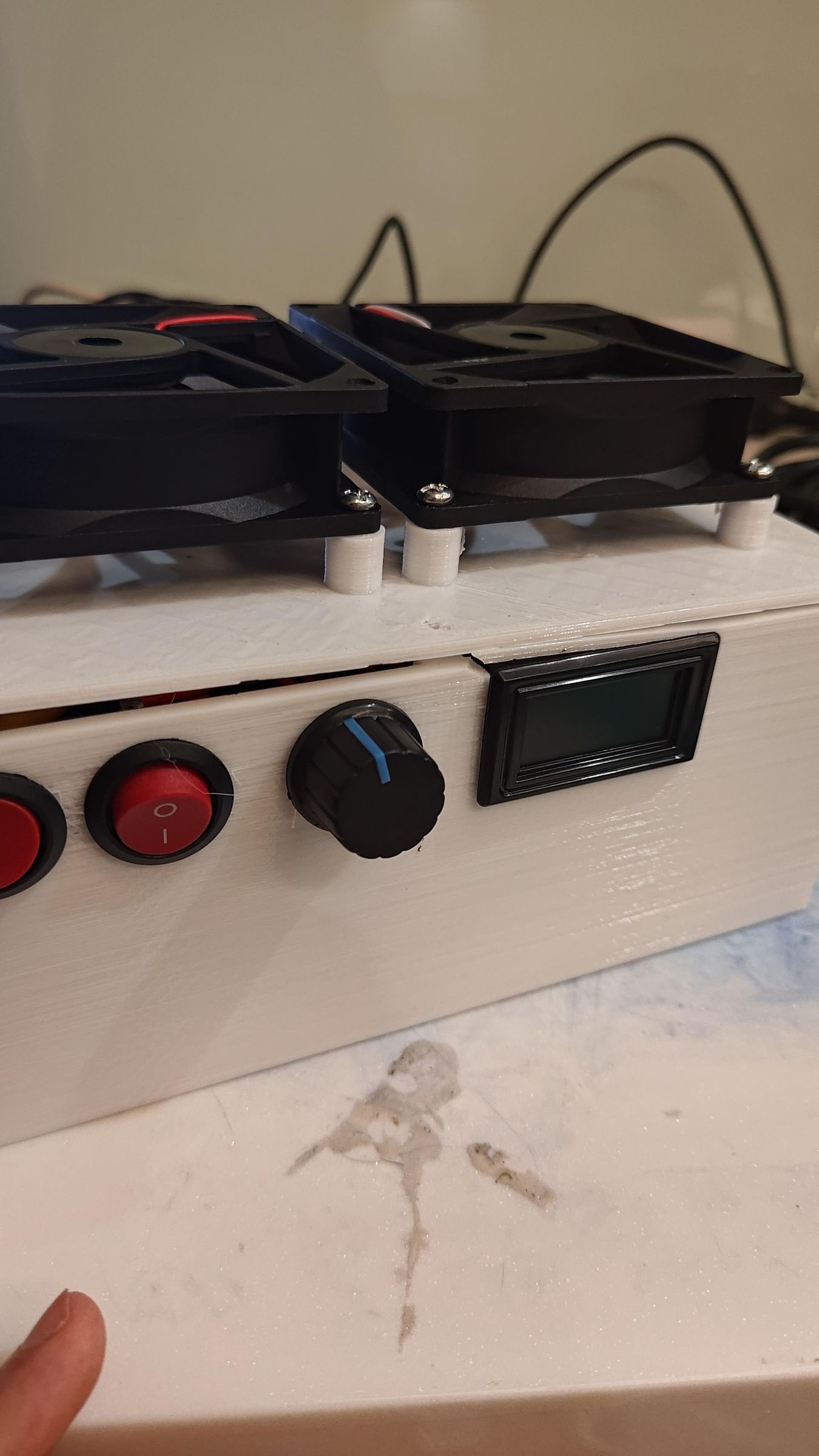
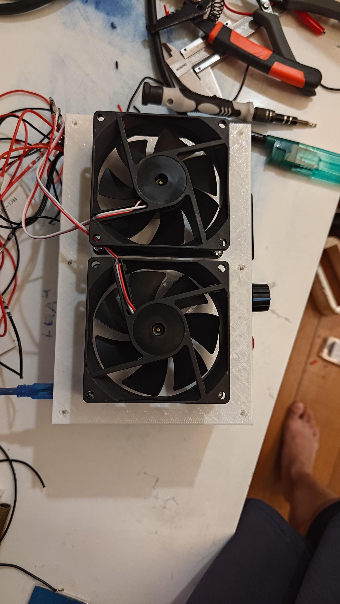
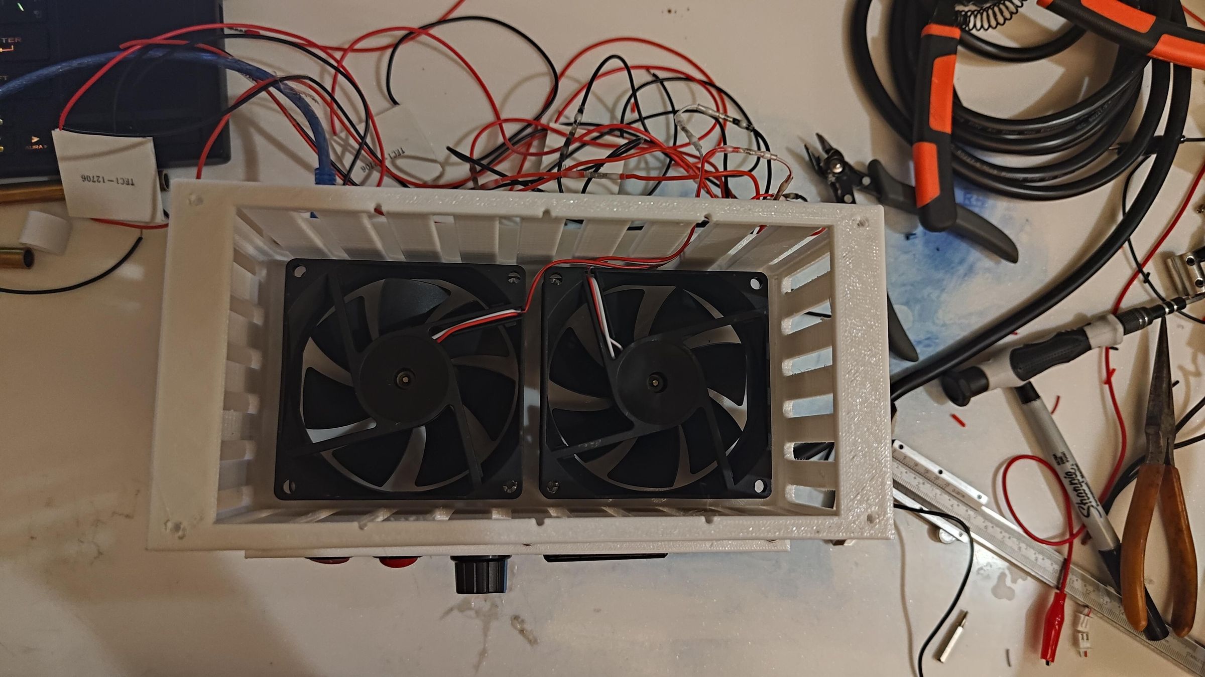
The fans are just mounted on the fan mounting plate, where they blow air upwards into the heat sink to help dissipate heat. Make sure to mount the fans in the correct orientation for correct air flow direction (check in pictures).
Mounting Heatsink
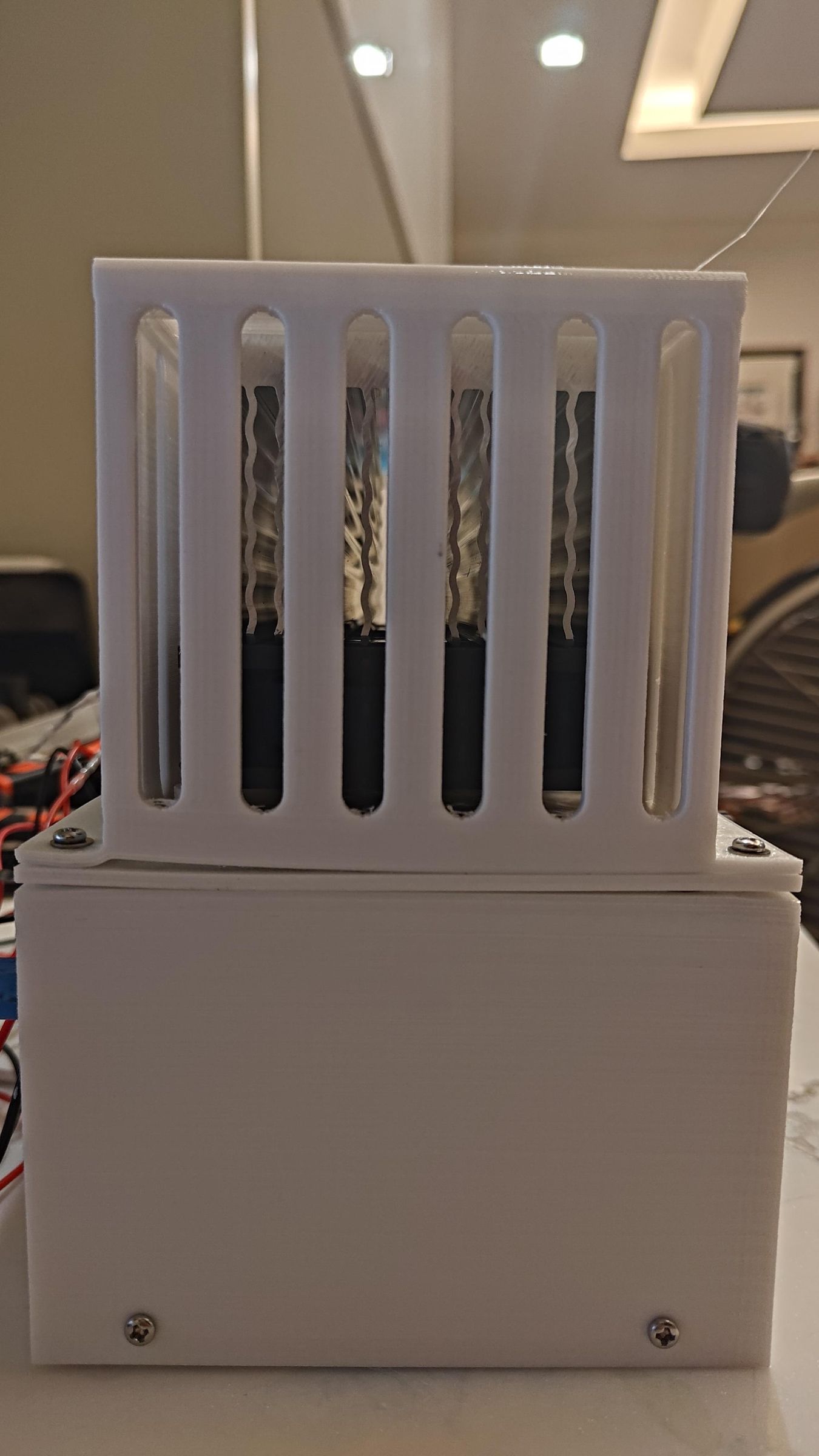
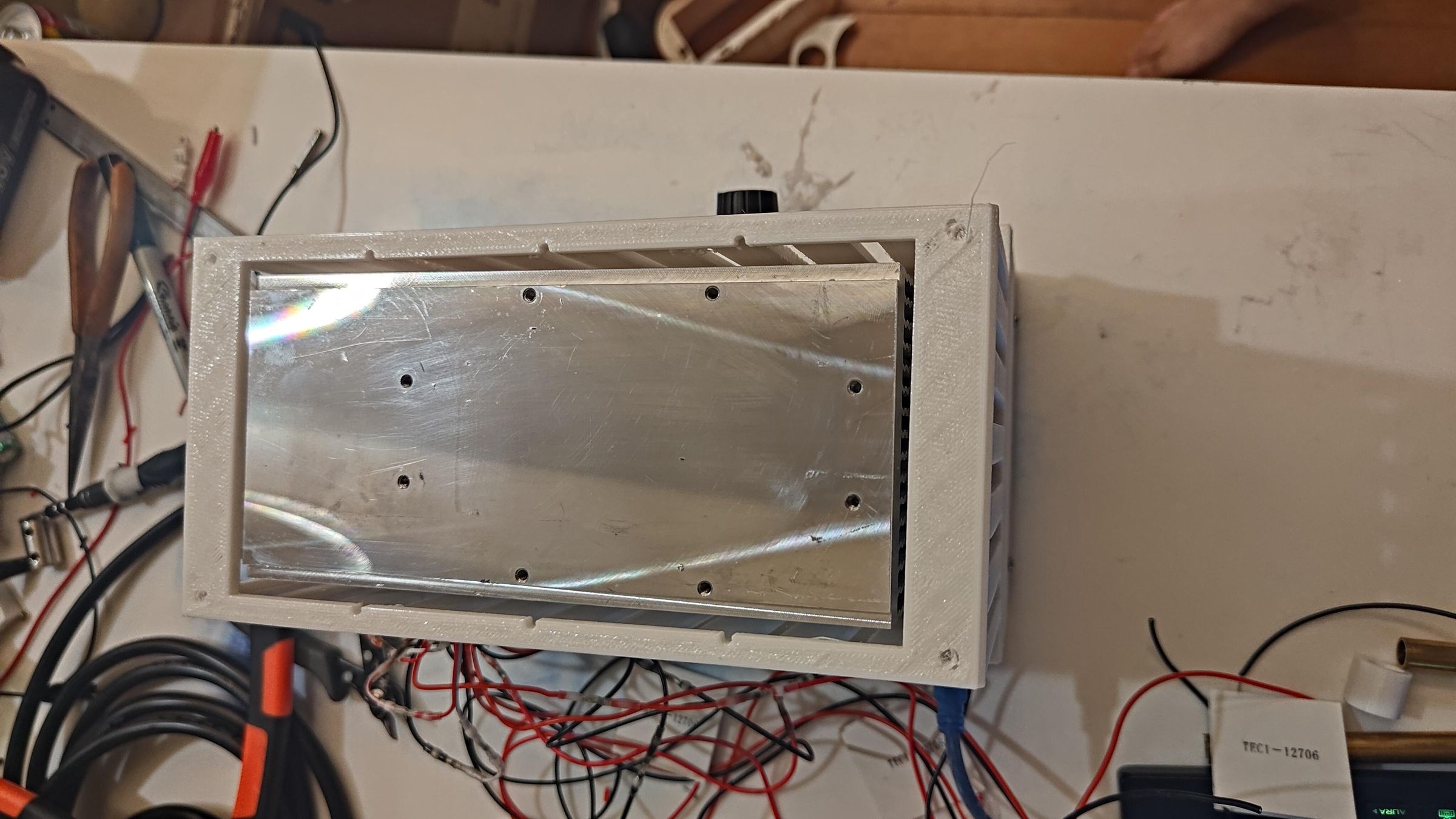
Just drop the heatsink onto the fans making sure the flat surface is pointing upwards. The heatsink is then centered and held in place using the Heat Sink Mount (.stl).
Placing Peltier Modules
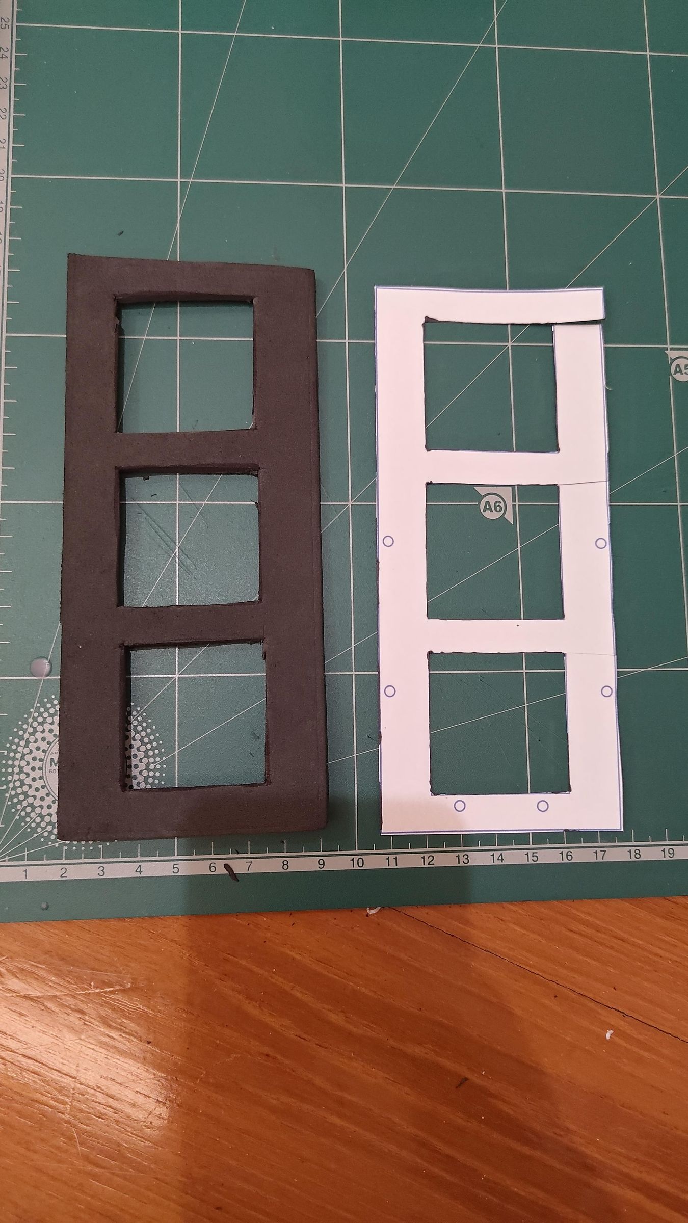
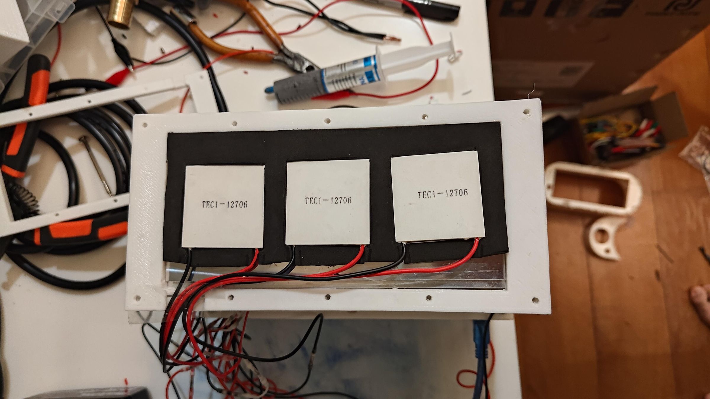
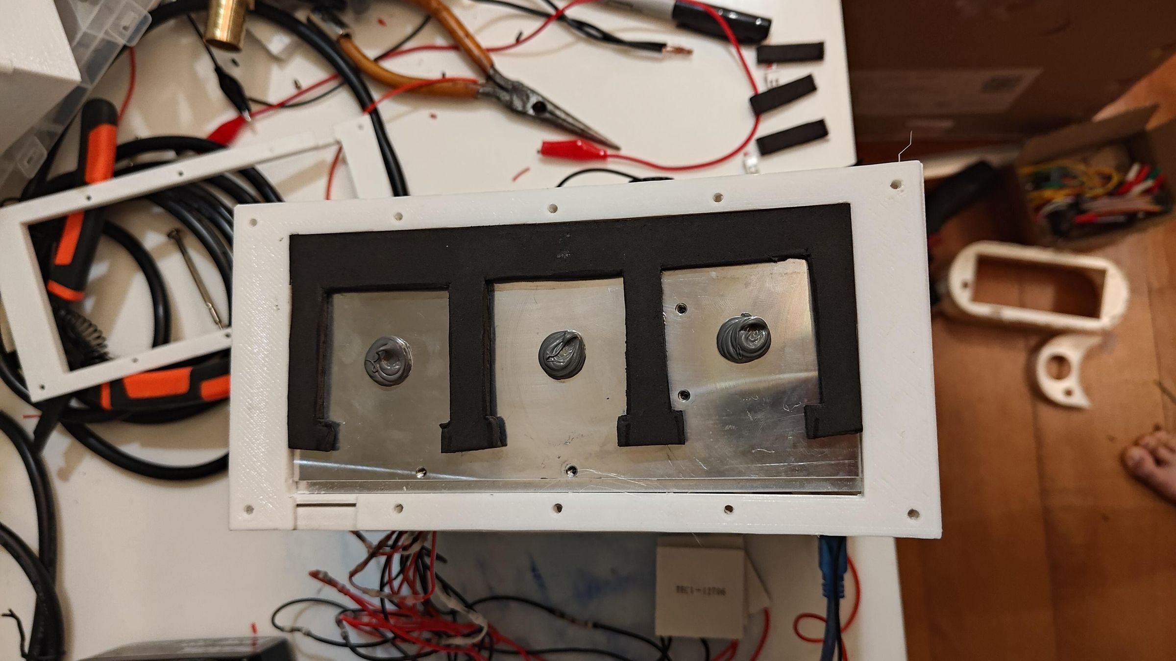
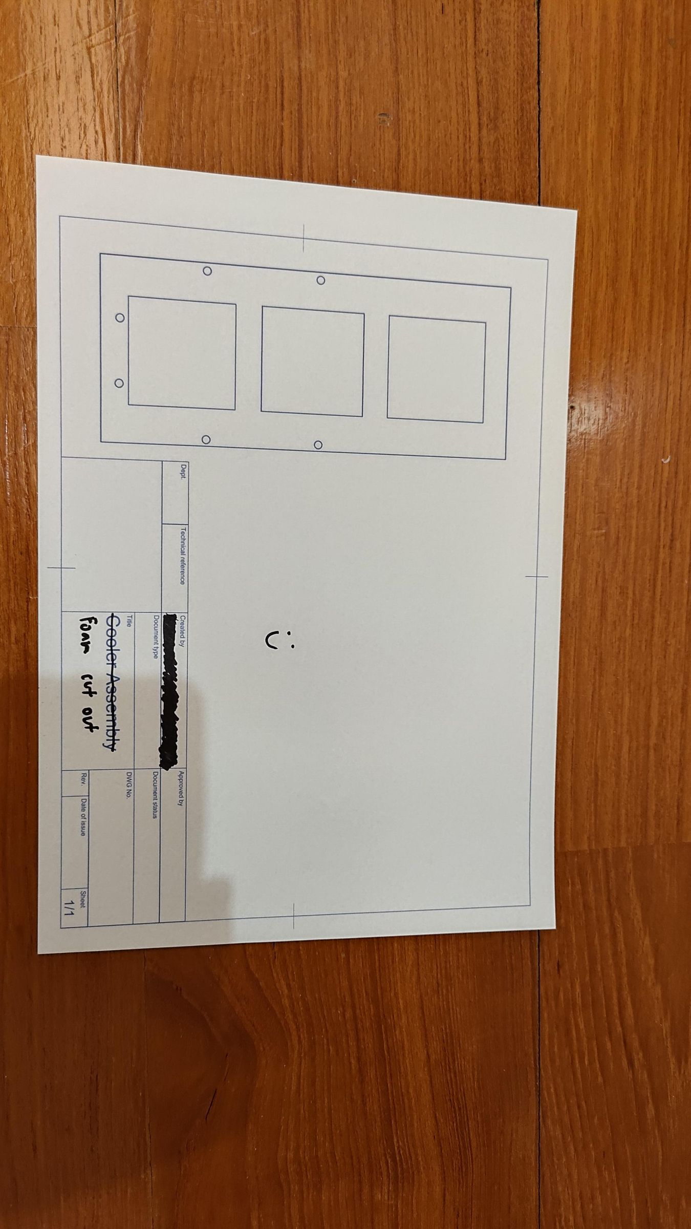
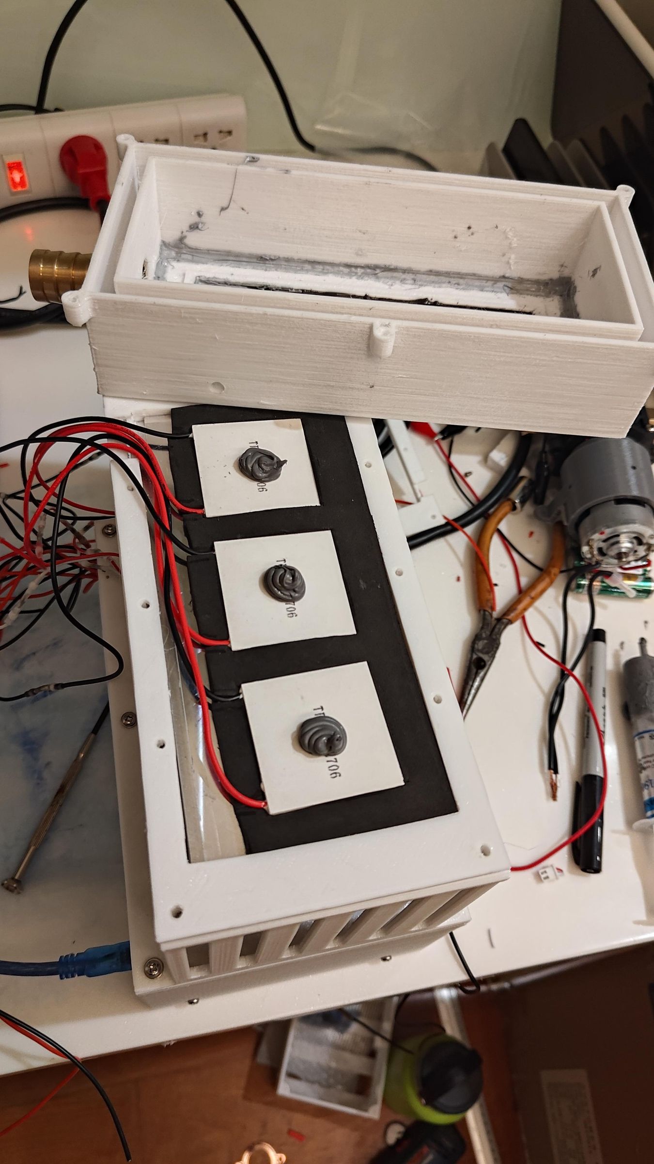
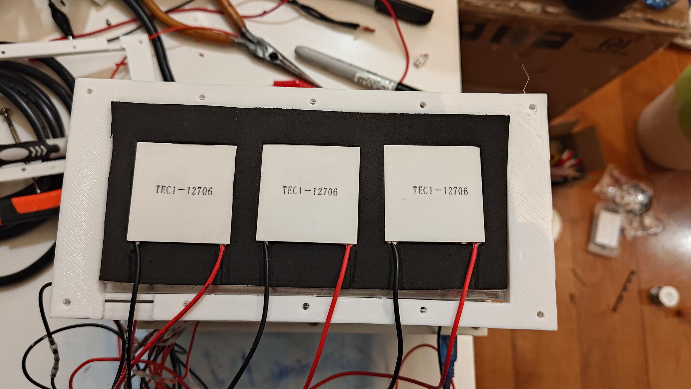
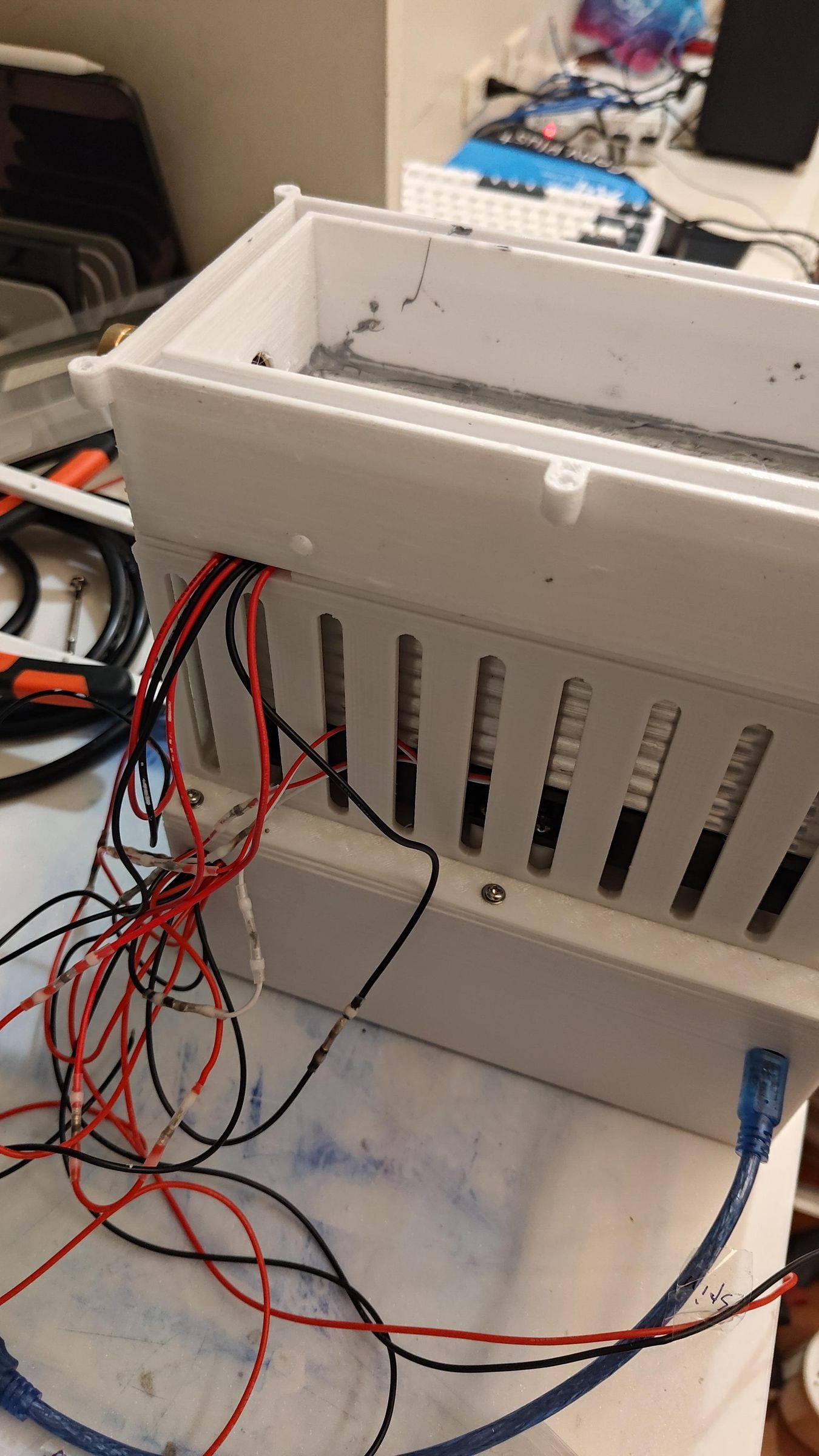
I used Fusion to make a 1:1 scale of the cutout for the foam (insulation) in the drawings. Then printed it out on paper and used it to cut out the exact shape for the foam. And as you can see in the pictures, the Peltier modules fit in perfectly (they look so cozy).
Then thermal paste is applied to the bottom and top of the Peltier modules. Make sure to press on the Peltier modules/aluminium sheet above to uniformly spread the thermal paste. This is quite crucial, as it allows for max thermal transfer and prevents any air gaps.
Downloads
Inserting Aluminium Sheet
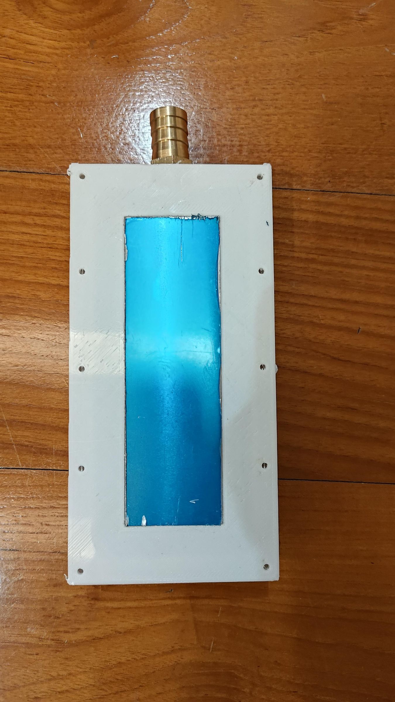
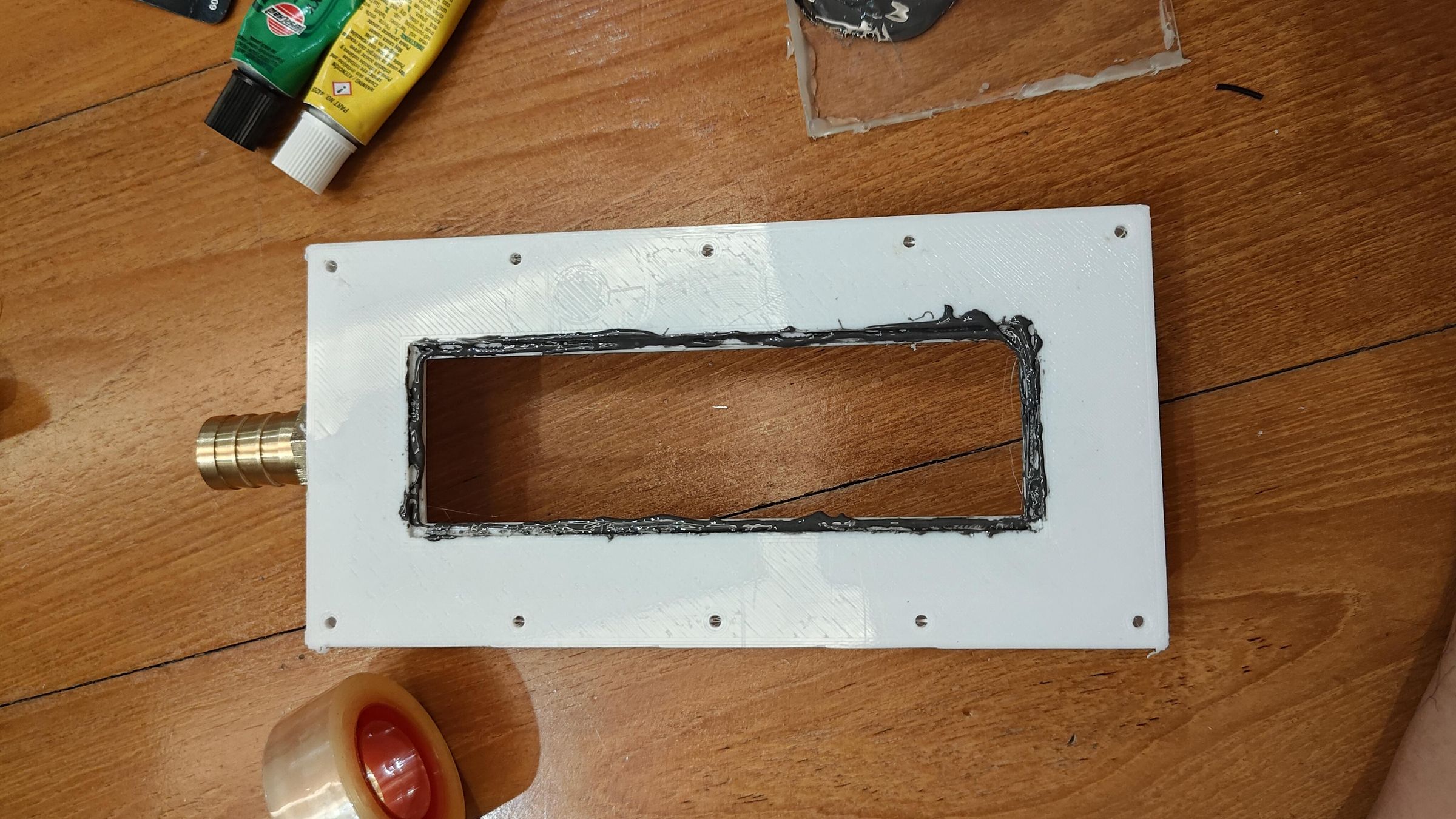
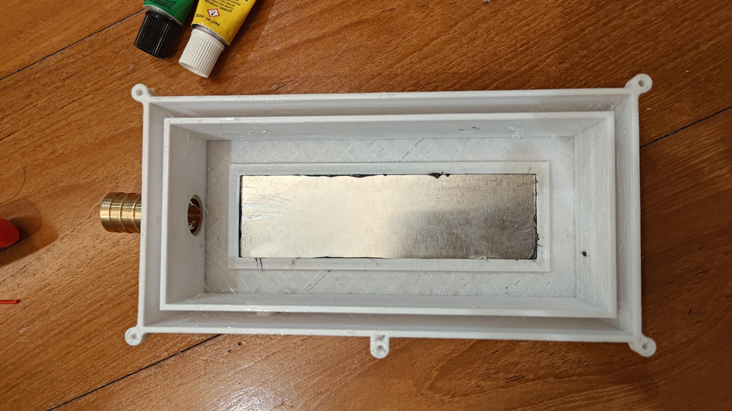
Apply epoxy to the crevices of the mounting slot, then align and insert the aluminium sheet. The aluminium sheet acts as a thermal transfer medium from peltier module to the cooler box, where it then cools the water. Aluminium is an excellent conductor.
Aluminium sheet size: 46 x 146 x 2 mm
Don't worry, I removed the blue lining/sticker on the aluminium later, after the epoxy had cured. Just to prevent any epoxy from making direct contact with the surface of the sheet itself, which would reduce efficiency and create an uneven surface.
Insulating Box
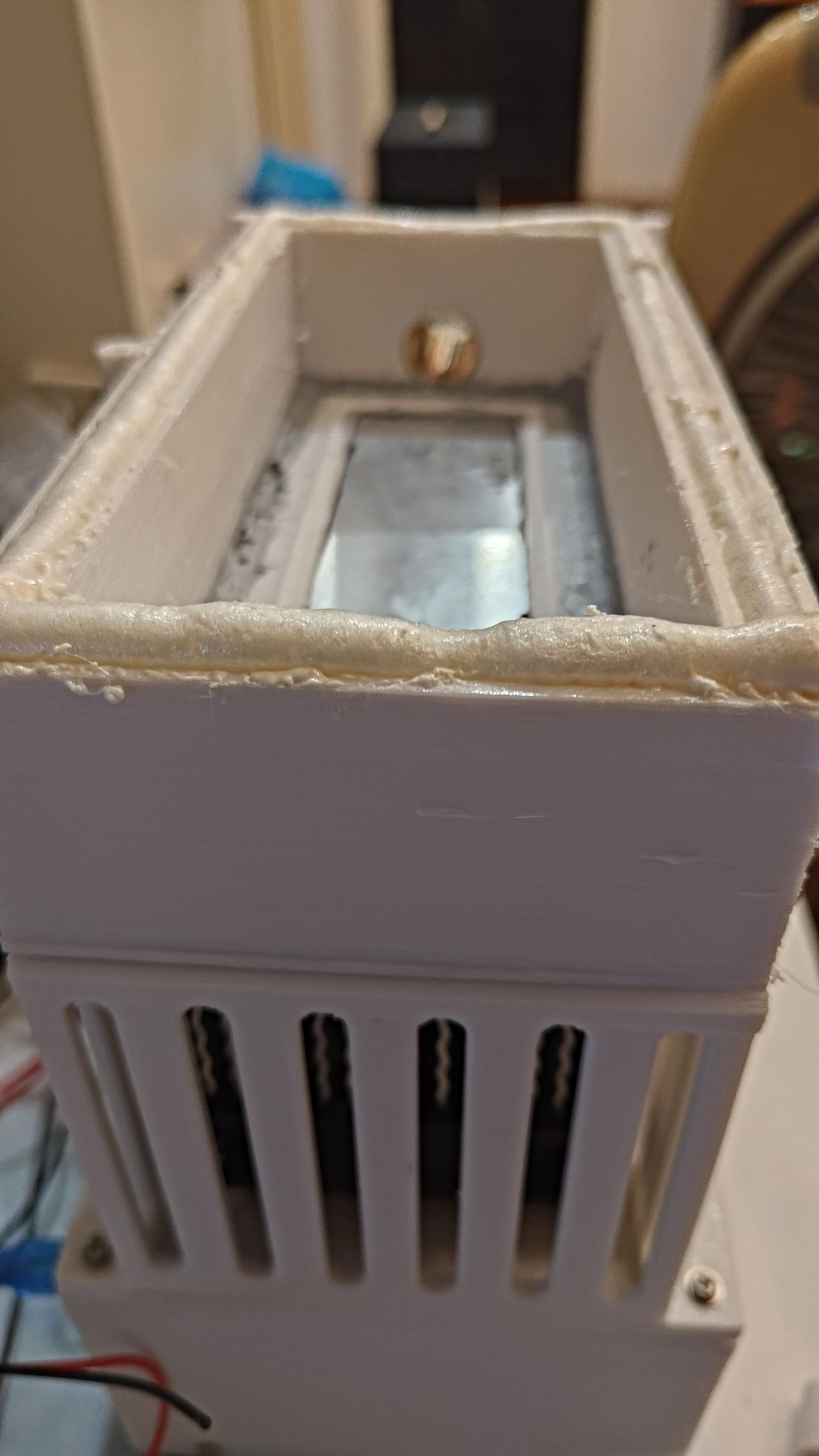
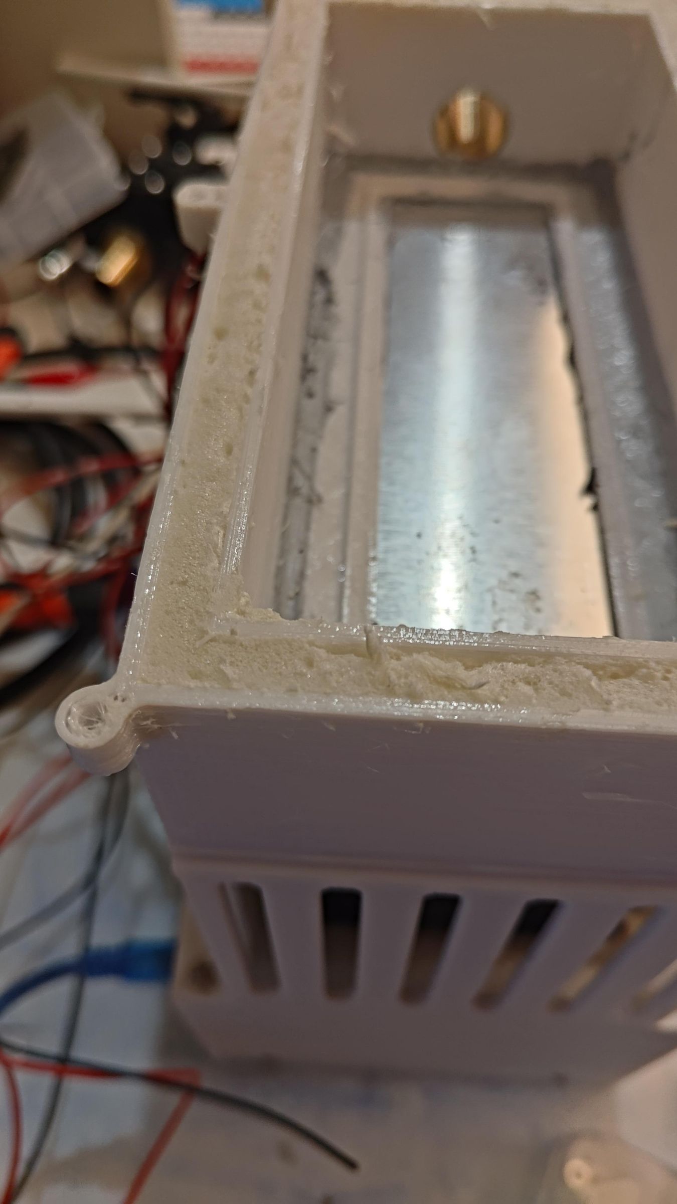
For this project, I tried using PU foam for the first time, so that was something. I sprayed the foam and allowed it to expand and cure, then cut the excess parts. I think it was a good decision to use it, as not only is it a good insulator, but it also allowed me to get into small crevices in the cooler box. The cooler box has multiple holes going into and out of it. So it was important to insulate that
Assembling Wet Chamber
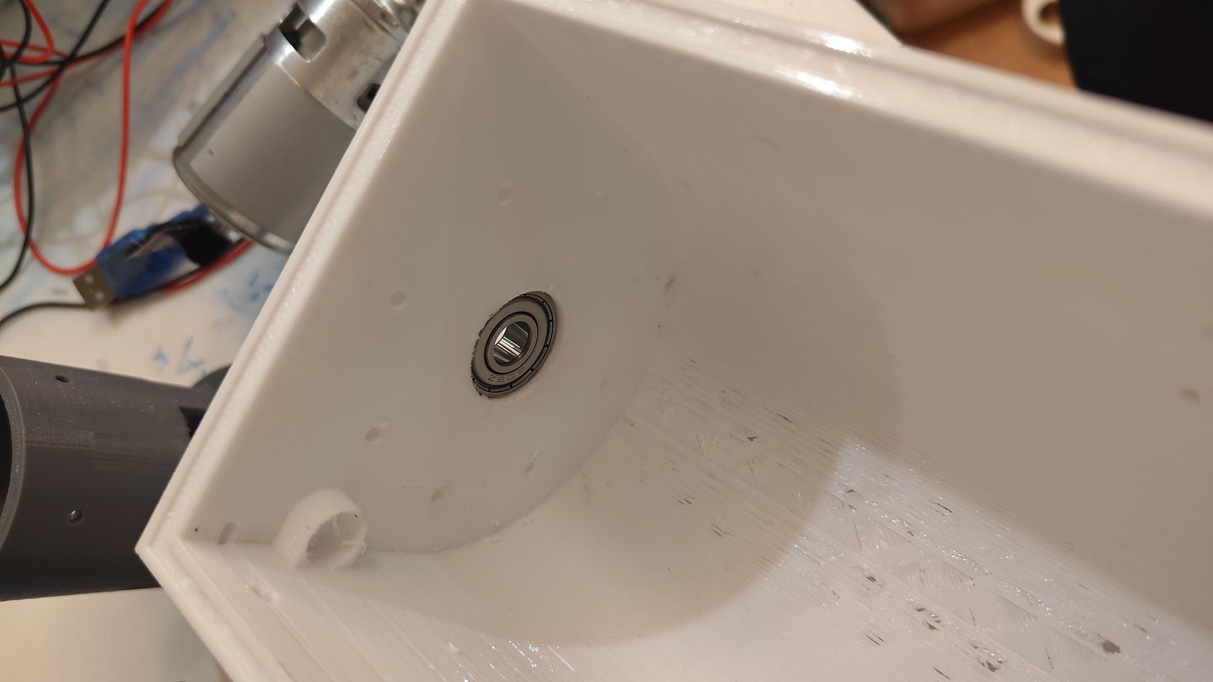
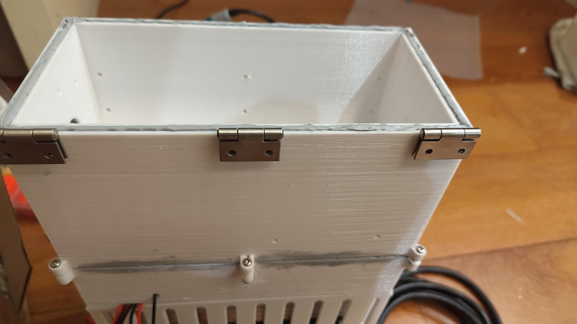
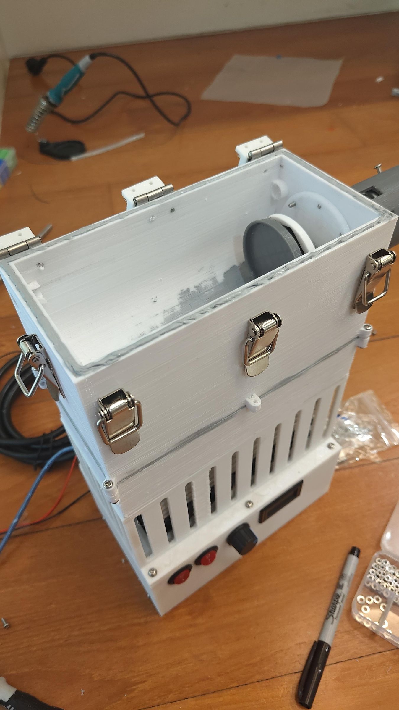
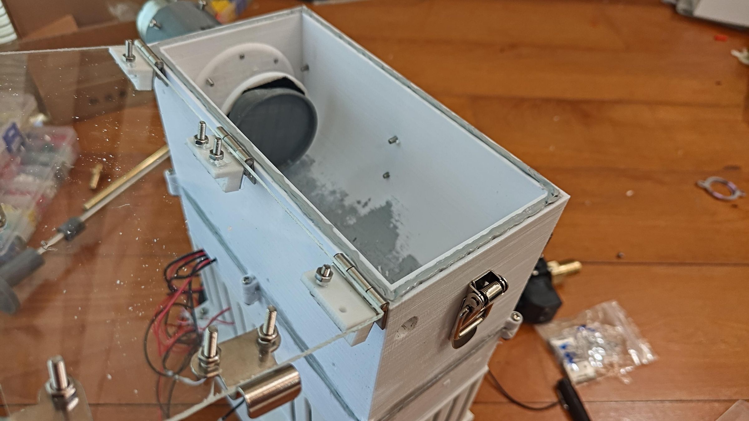
The Bearing was press-fitted into the chamber. The latches and hinges were also screwed in and connected to the acrylic panel. I also used the gasket maker here for a seal between the acrylic panel and the box itself. Using the gasket maker was so much easier than cutting out your own gasket.
Here you can also start to see me use weird and different lengths of fasteners/screws. This was because I ran out of them, so I had to use other lengths. Which unfortunately made it look less aesthetic. :(
Acrylic panel size: 96 x 196 x 3 mm
Motor Assembly
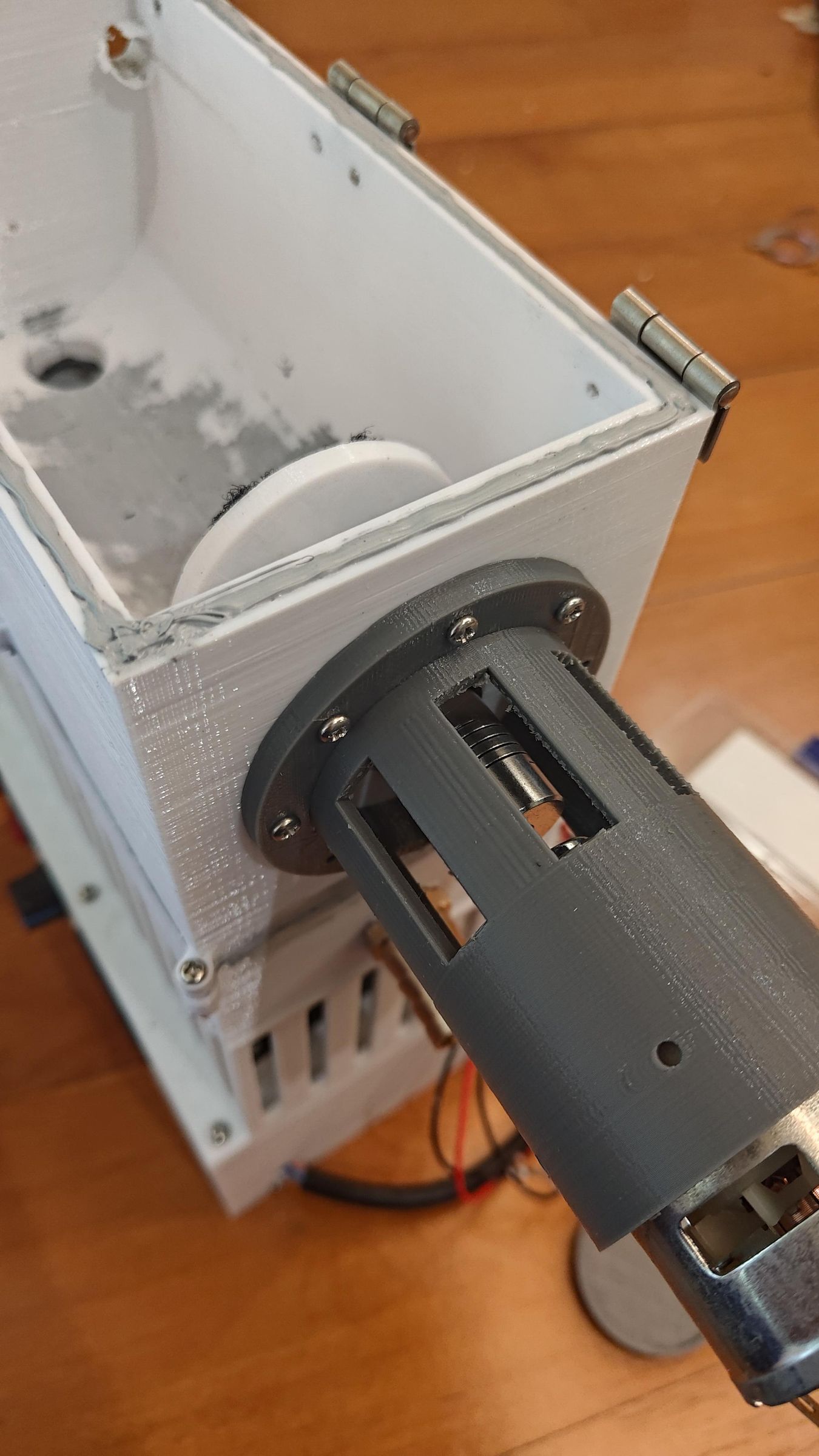
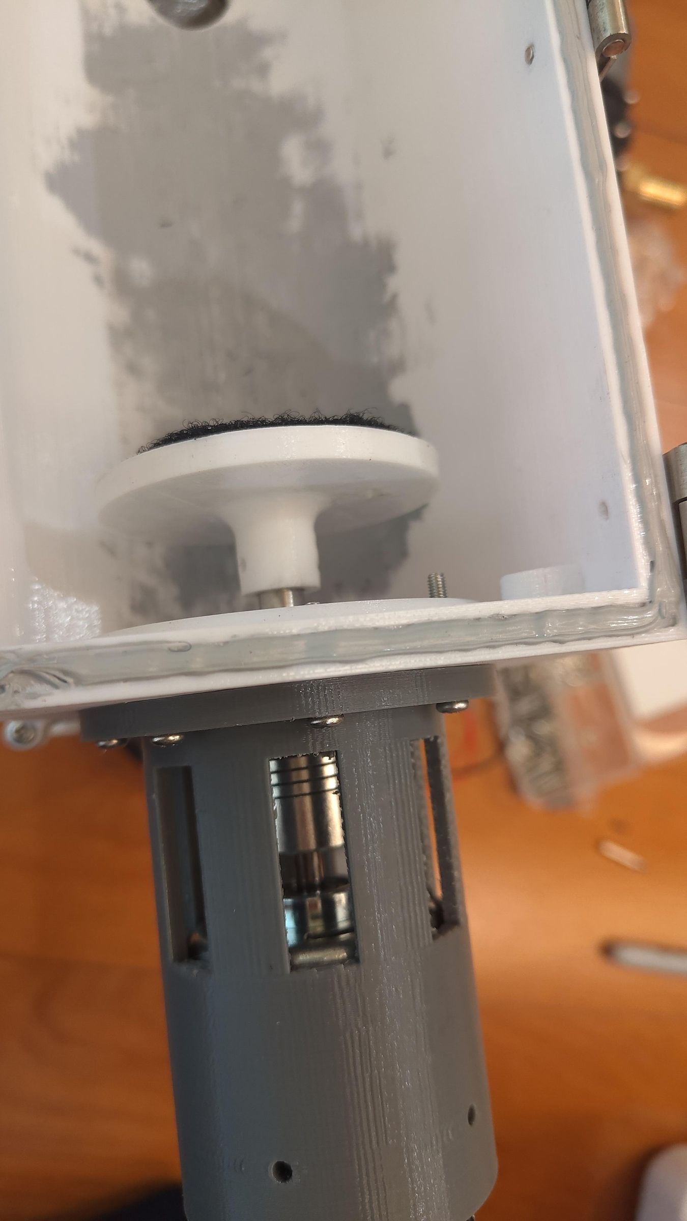
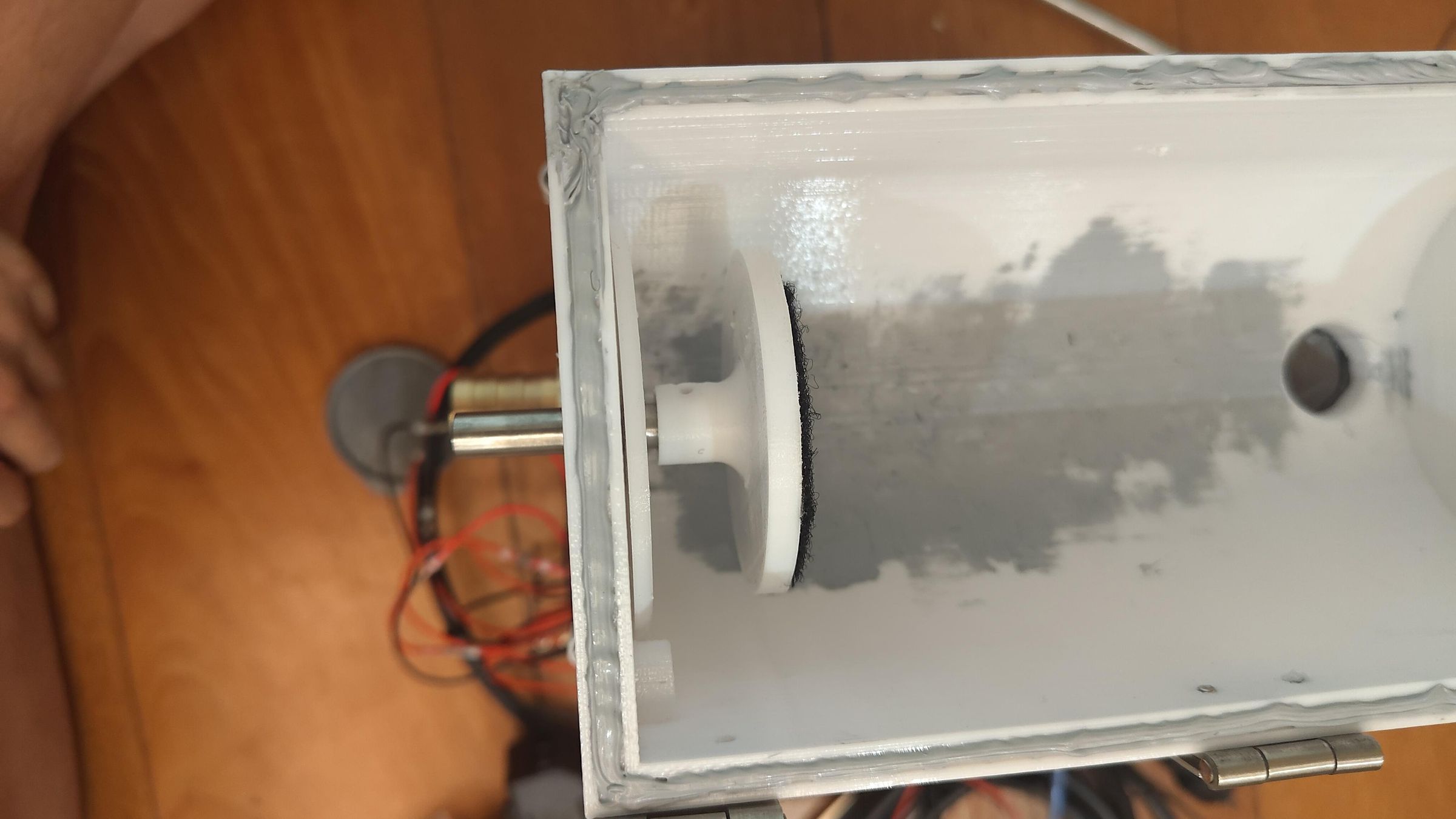
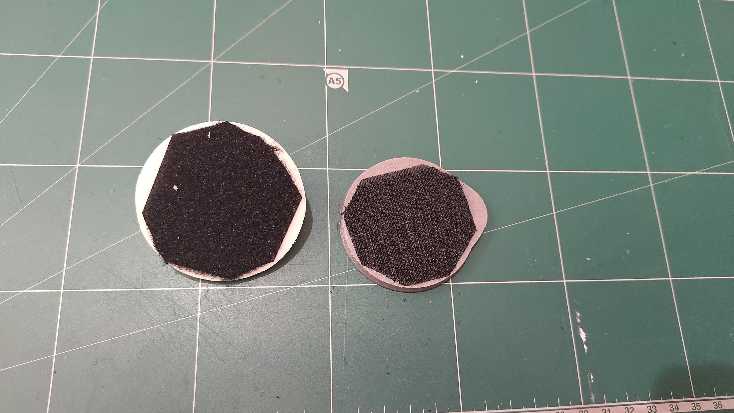
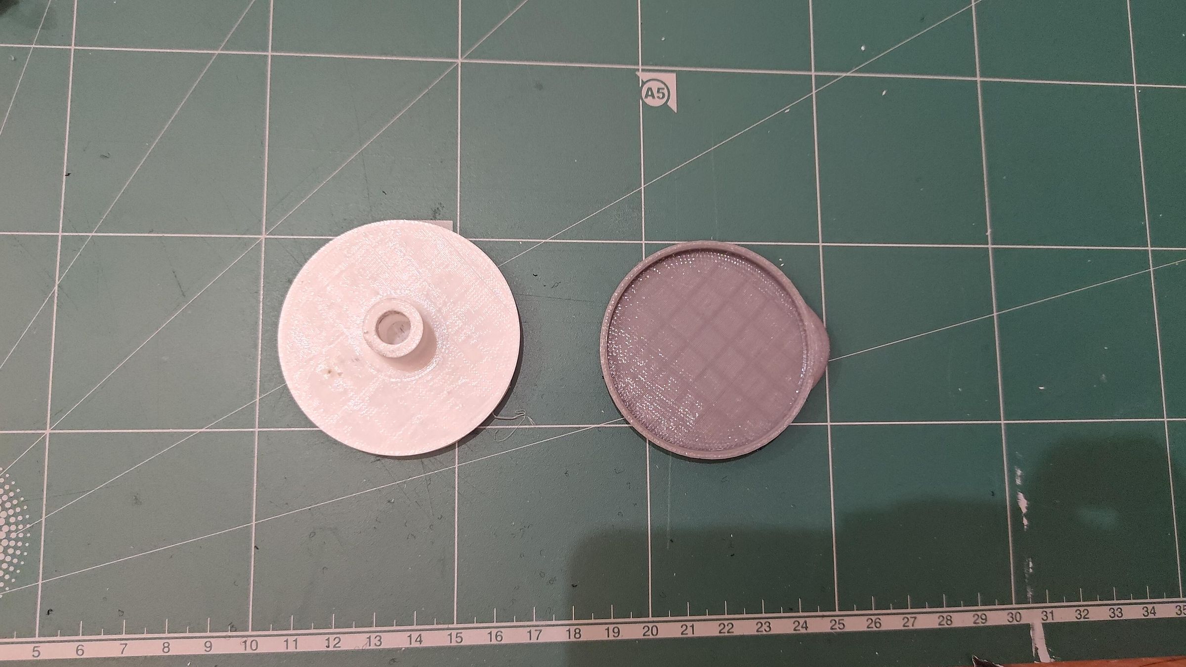
Firstly, sand the Velcro surfaces on the 3D prints with low-grit sandpaper to give a rough texture. So that the adhesive side of the Velcro sticks to it much better. Then apply the velcro.
The 8mm shaft is then inserted through the bearing where it connects to the drink can holder on one side and the coupling on the other. The 775 motor is of course connected to the 5mm side of the coupling. Then the whole motor side is contained within the motor mount/cage to give it better support and prevent it from moving.
Attaching Pump
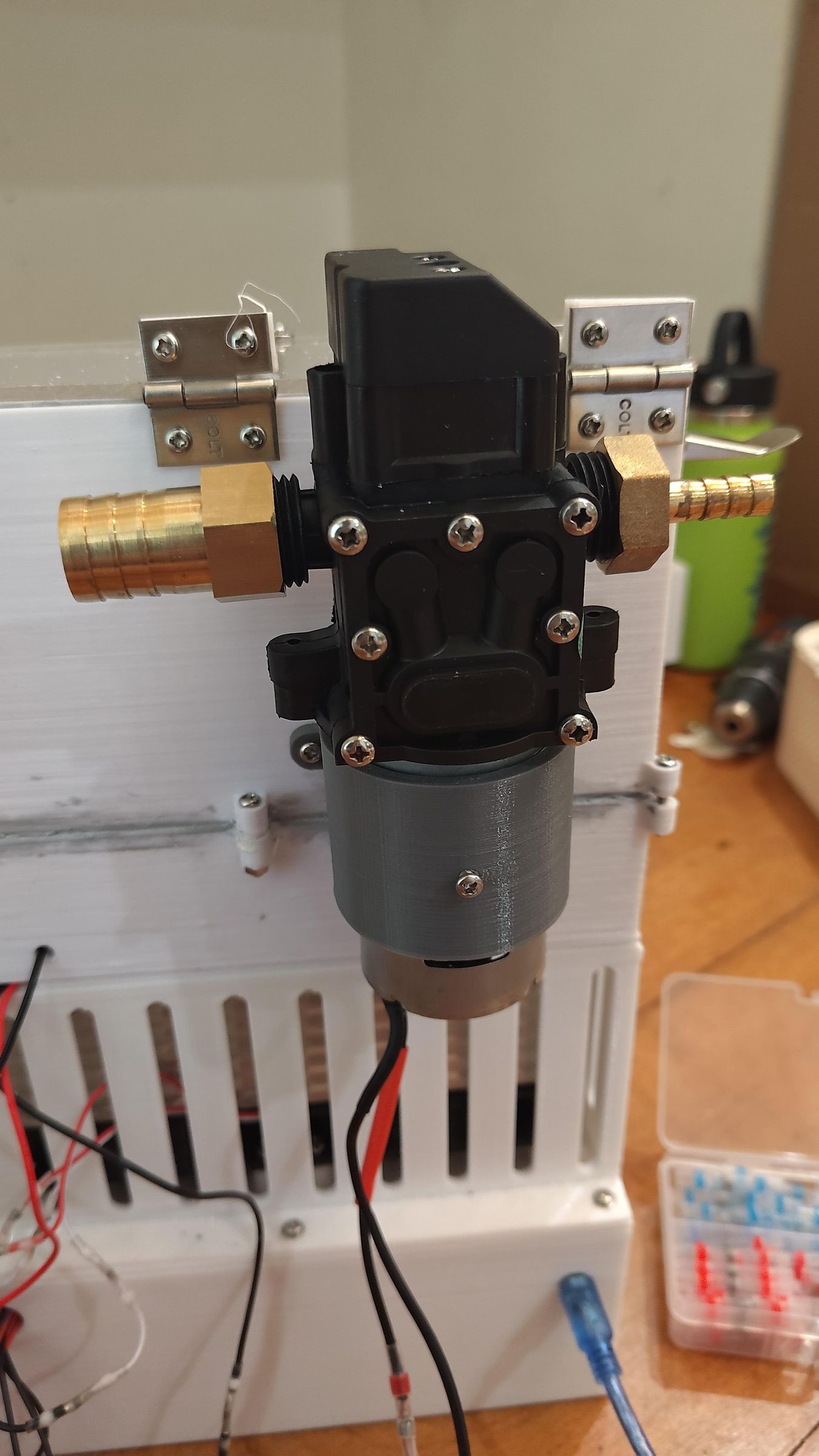
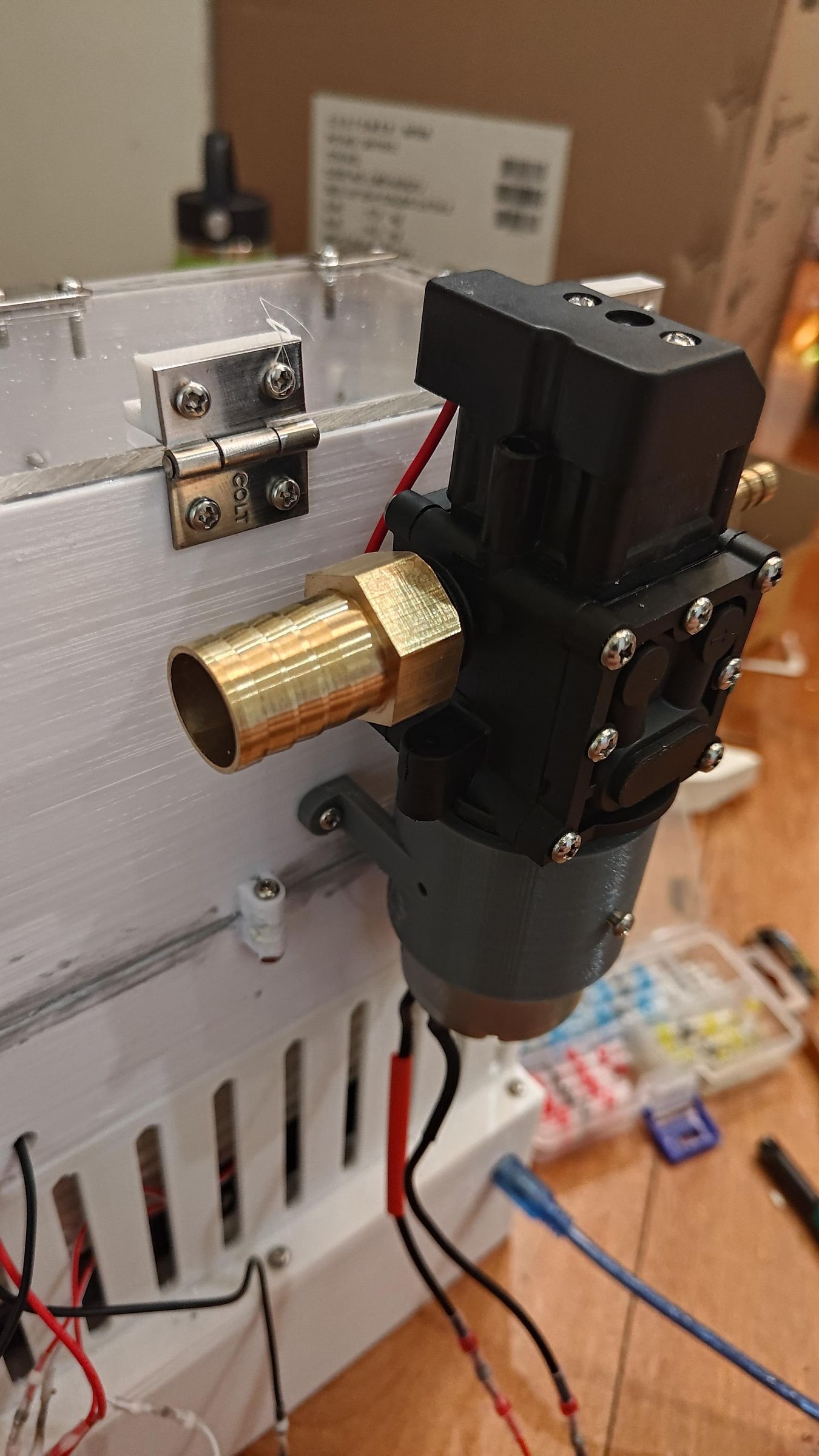
The pump used here is a 12V diaphragm pump. The reason I chose this was that a diaphragm pump is more resistant to lower temperatures and higher concentrations of ions (salt). This would be important later on, when I wanted to experiment with sub-zero solutions to hopefully get even better performance.
Plumbing
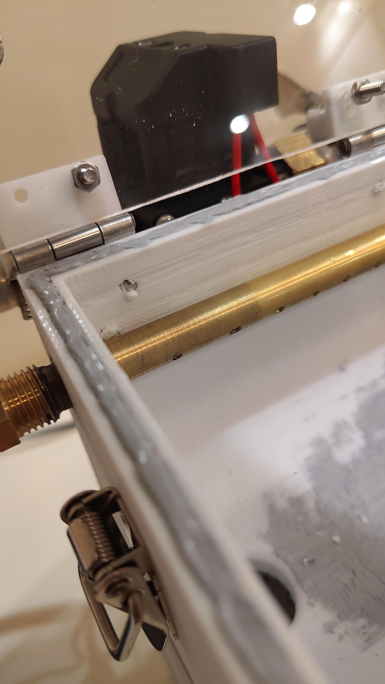
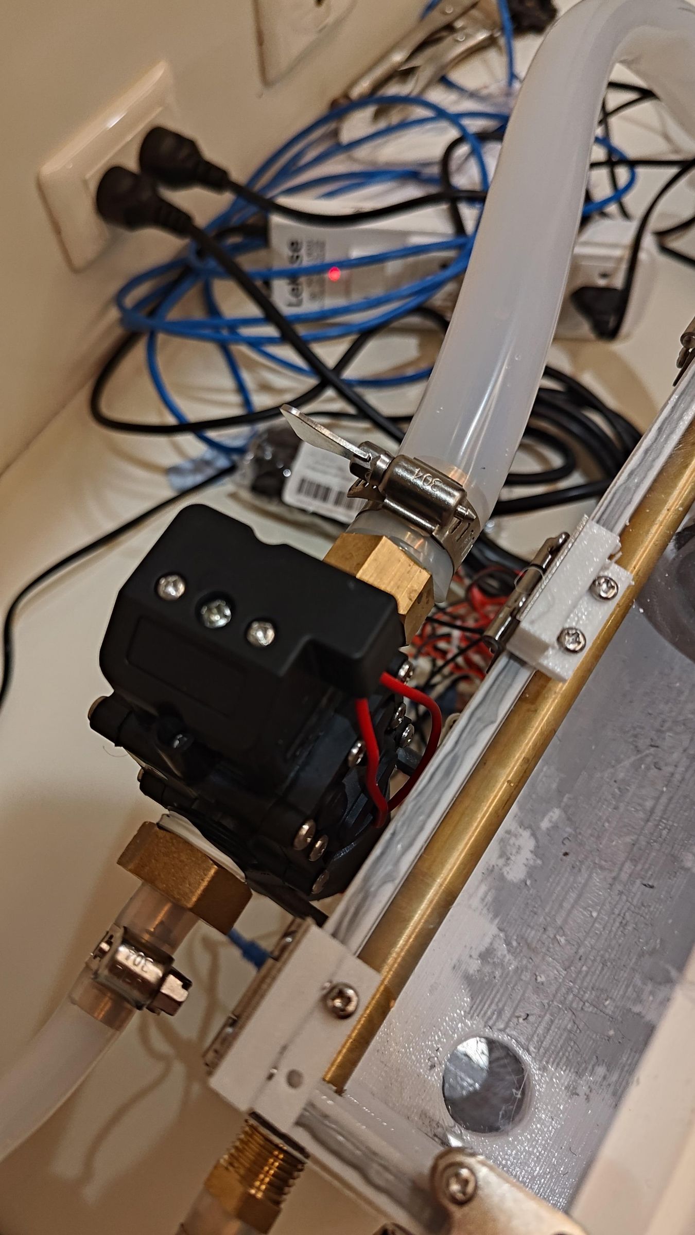
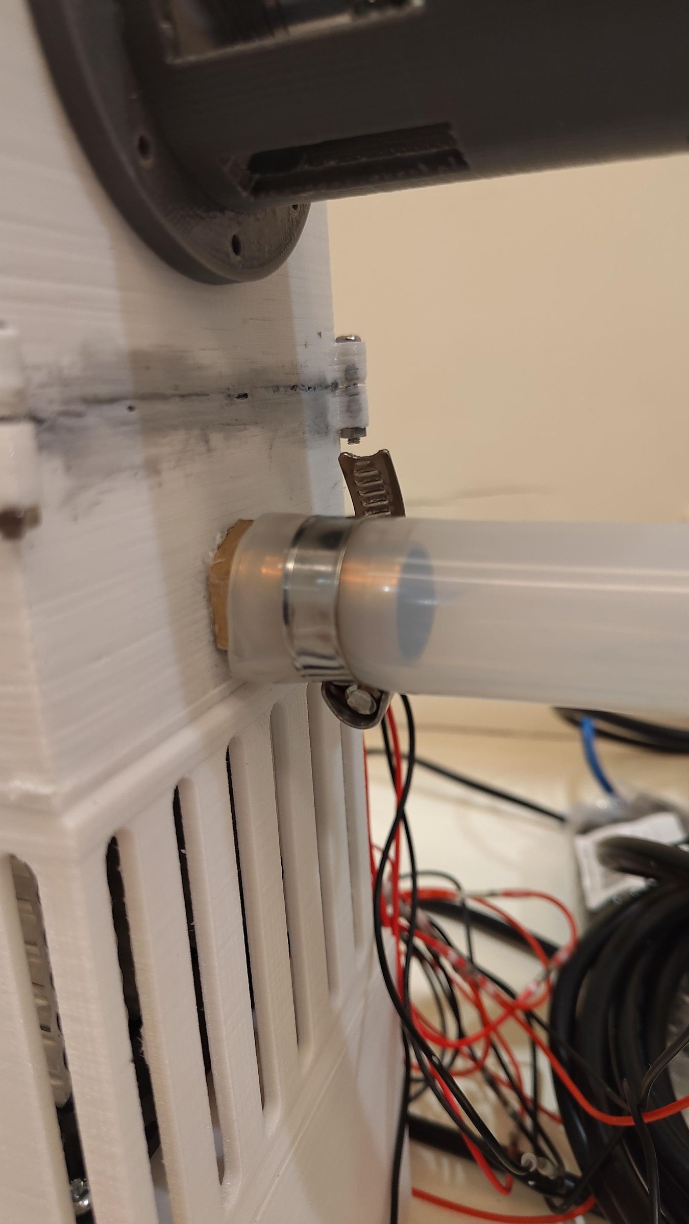
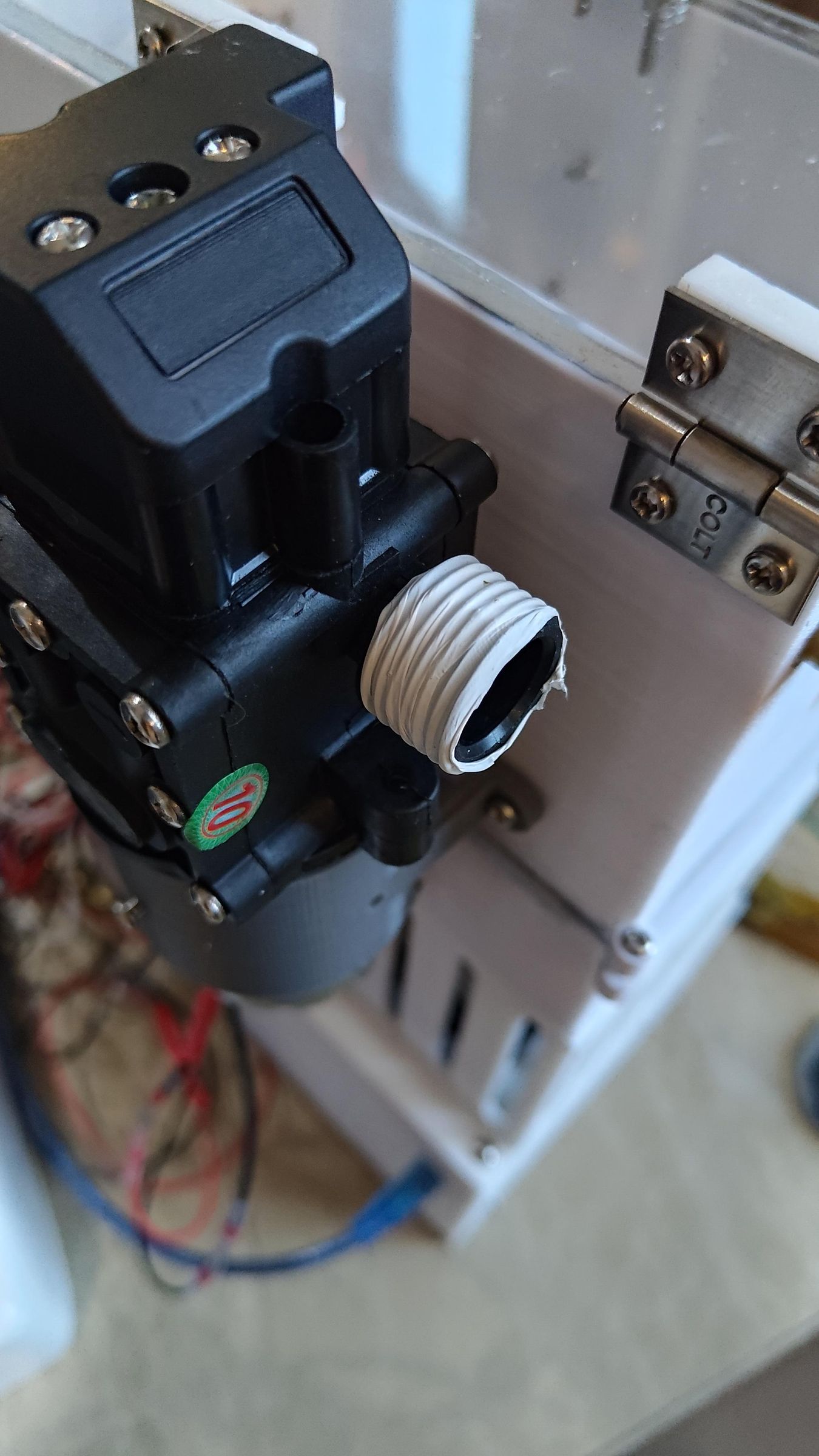
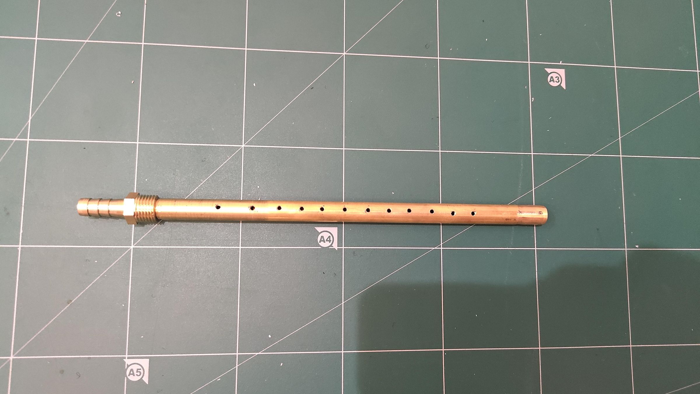
Teflon tape may be useful here
As mentioned in the materials list, for the brass fittings, you should either use NPT or BSP. Do not mix different fittings together, as they will not fit, and you would be left with an emptier wallet.
Insert Thermometer
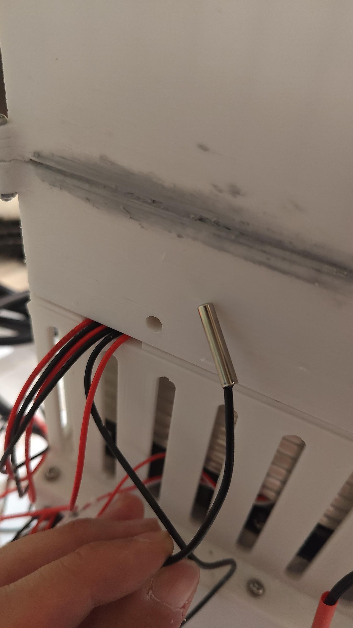
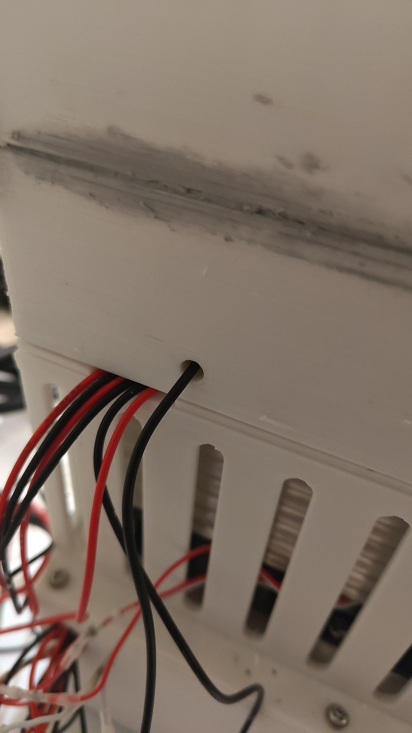
The thermal coupling is inserted into the cooling box, where it is then sealed to prevent any water from leaking out.
Software
In order to control the speed and direction changes of the 775 motor, the Arduino Nano must be flashed.
You also probably have to change the pins to the correct ones for it to work
Downloads
Testing/performance
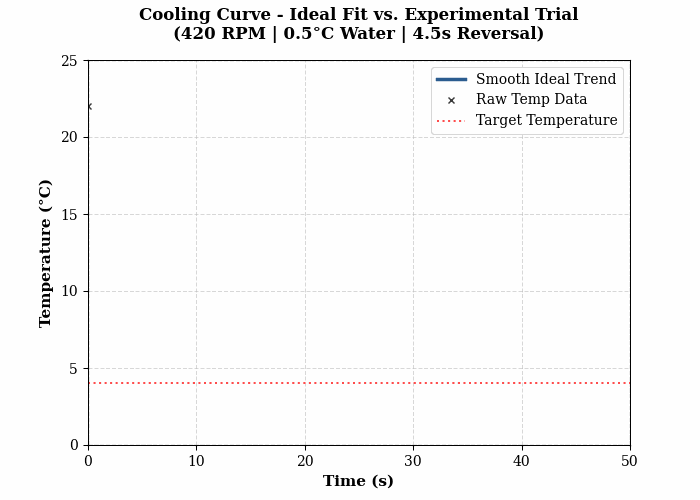
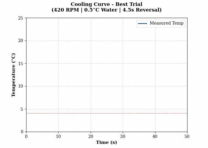
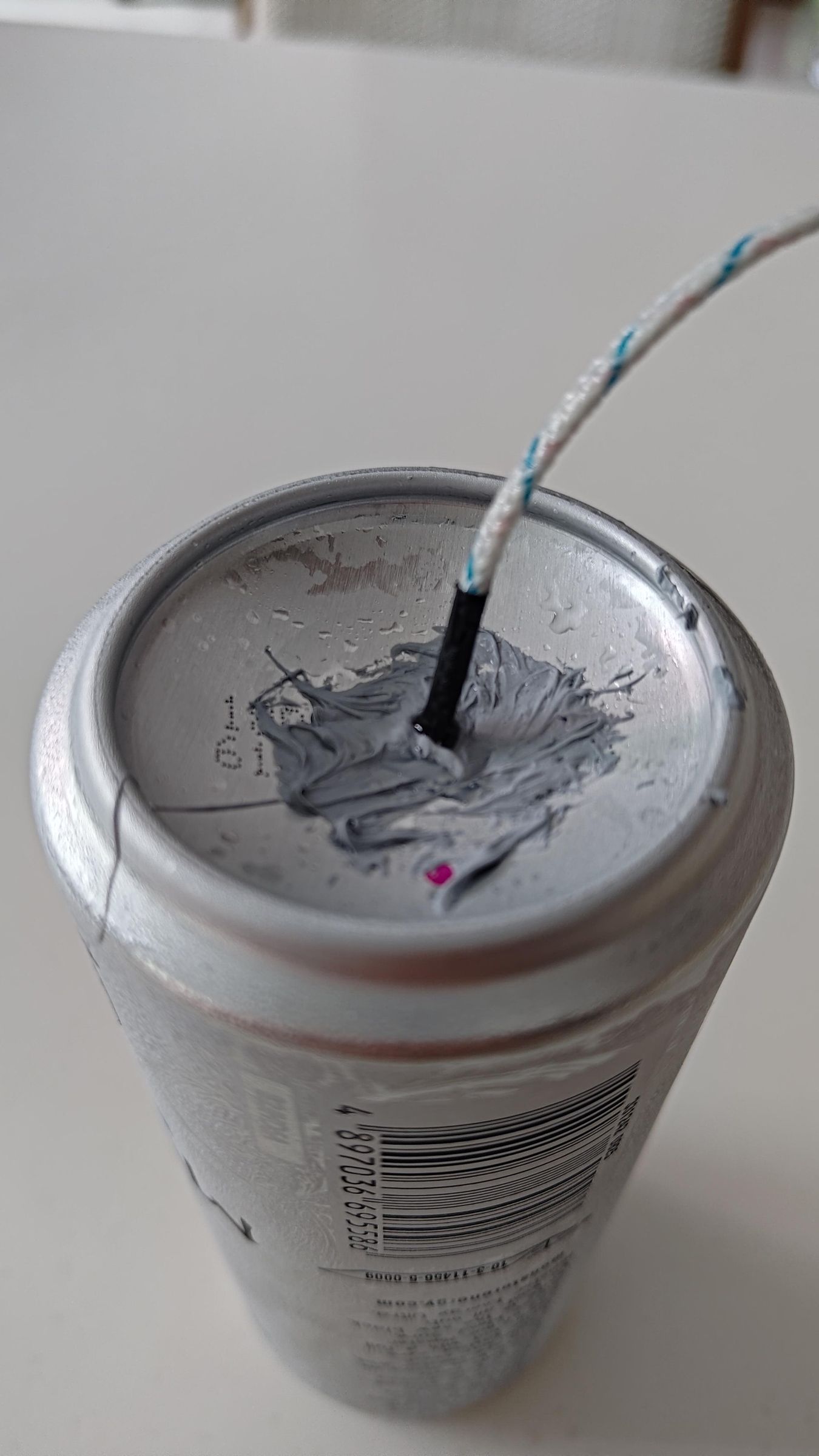
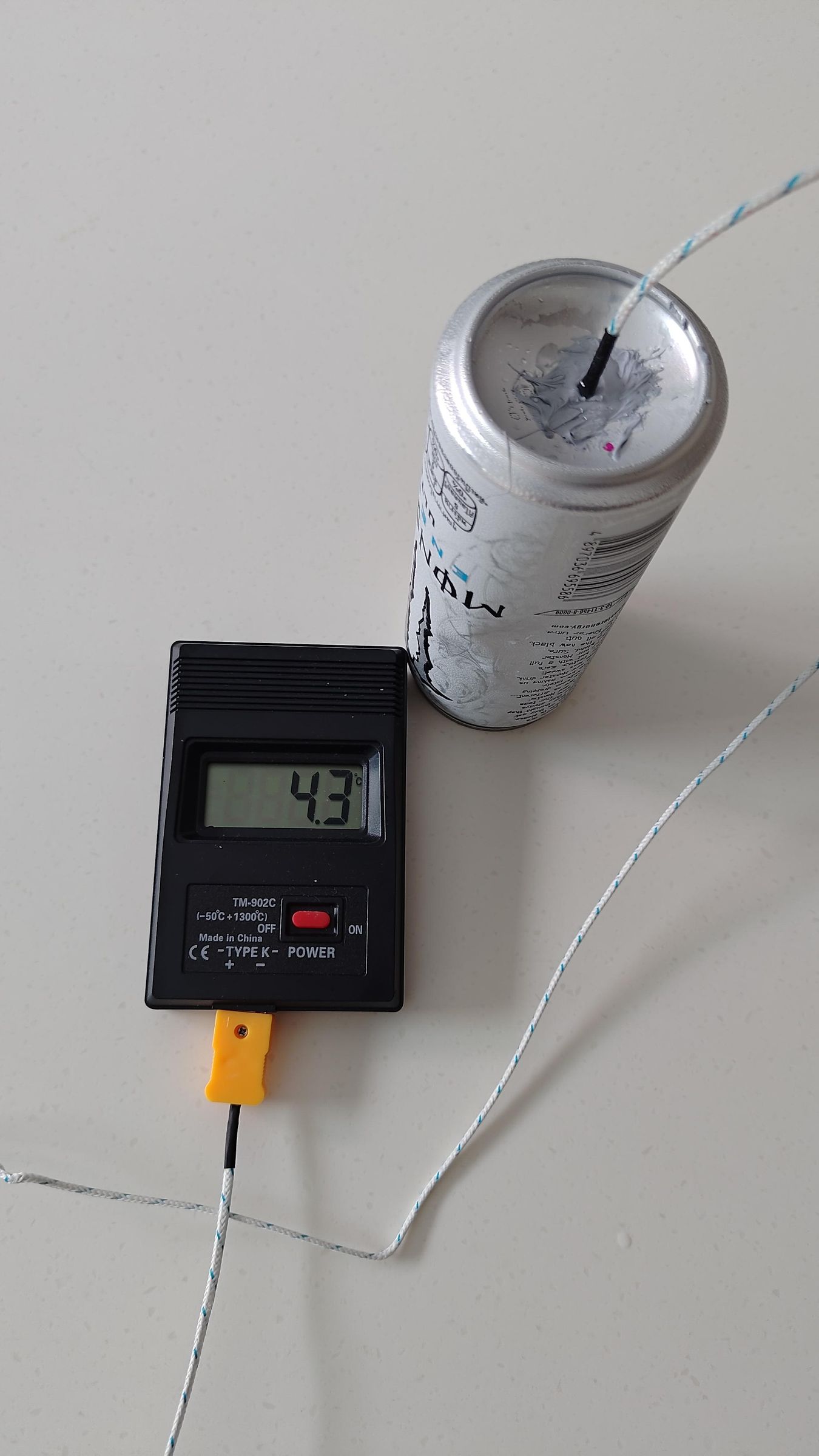
In terms of the performance of this machine, the best trial I got was approximately 48 seconds to cool a 330ml can from room temperature (22°C) to 4°C. For this trial, the parameters were set as follows: 420rpm, 0.5°C water, 3s reversal window.
The method I used to collect the data was inserting a thermocouple probe into a can and sealing it. Then, as the machine was running, I would record the thermometer reading. Afterwards, I would record the temperature of the can on a sheet every second using the video. This method, although not as accurate as using a data logger, was still pretty good for what I was doing. The RPM recording was also not using the calculated value in the Arduino code, but an actual tachometer, as the calculated value and actual value do differ due to load on the motor.
Parameters:
Water Temperature: You want the temperature of the water to be as low as possible. Heat transfer is driven entirely by the temperature differential between the warm can and the cold water. In the future, using sub-zero water/liquid would definitely improve the performance, perhaps a salt-and-water solution.
Rotational Speed: You want the RPM to be about 350-400. Reasons you should even spin it are discussed above. But there is a limit if you spin it too fast. If spun too fast, solid-body fluid pinning occurs. When the centrifugal force becomes too intense, the liquid pins itself completely against the wall of the can. Where a hollow pocket of air is formed at the center, and the fluid no longer mixes.
Reversal Window: Discussed above
Downloads
Bonus/BTS
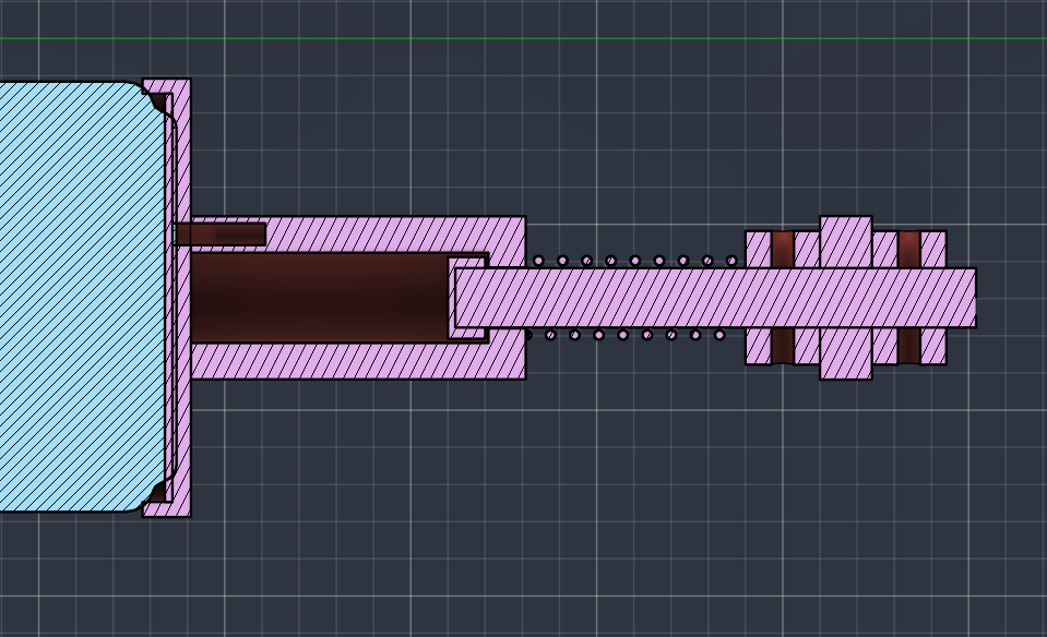
As for these projects, I think it's important to talk about some of the processes or look behind the scenes. As I think it may be useful for some people reading this to know about some of the iterations I took and also the design considerations.
I left out some designs/components for this project, such as a tailstock, as when I did some tests, the can spun fine without needing a tailstock. So I just dropped it to keep things simpler.
For some design considerations to attach the can to the motor assembly, I chose to use Velcro instead of rubber rollers like other designs for ease of removal, as well as the can needing to be rotated in alternating directions constantly, which caused crazy changes in momentum that would make the can slip and lose traction on regular rollers. But with Velcro, this problem was solved, and it kept the can spinning perfectly in sync with the motor.
There are definitely a few things I'd like to fix for the current design. I'd add some rubber feet to the bottom to help with damping from motor vibrations and keep the whole thing from shaking around too much. I'd also swap silicone hoses for metal pipes to prevent kinking, which restricts the water flow, as well as making it more compact. And of course, look into wire management, as right now my wire management is horrendous. I should also mention a con of the design is that when removing the can, it is wet and you have to dry it yourself, unlike some other products; however, the goal of this project is to cool a can as fast as possible (though I have added some features to help with convenience).
However, overall I am quite happy about how this project turned out. And will never have to suffer through a warm drink ever again.