Reactive Pixel Lamps

This Instructable details how to make a set of smart (wifi controlled) LED lamps. I created these pixel lamps as a way of creating ambient lighting and immersive gaming or film environments! Each pixel lamp is wifi connected and has the ability to react to the images being shown on the screen of your PC or TV as well as as being able to be controlled as part of a smart home!
I wanted to create the lamps to look like small pixels from an 8-bit style game so I opted for the cube style and made sure they were as cheap as possible so that many can be scattered around a room. Thanks to the wifi connectivity you only need a usb power source so theres no need to trail wires around your space.
In this Instructable I will walk you through how I created these lamps and give you all the files you need to recreate them yourselves! If you find anything that is unclear please let me know in the comments section.
Please note:
- This project doesn't assume any prior knowledge of electronics or programming but a working understanding of your 3D printer and how to solder is useful to use these tools effectively and safely.
- There are several risks that may be present when following this instructable from the 3D printer, soldering iron, hand tools, and glues. Please ensure you are working safely at all times.
Supplies
Electronics:
- Soldering Iron
- Solder
- Fume Extractor
- Snips
- Breadboard for prototyping
3D Printing:
- A 3D Printer (Or Access to one)
- Material (I used PLA)
Server:
- Raspberry Pi
- Pi Power supply
- SD Card for the Pi
Parts:
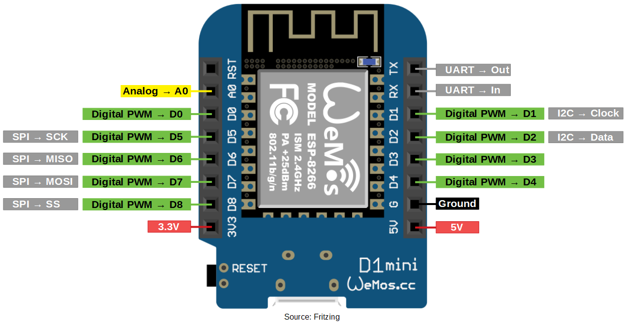
- Wemos D1
- Custom PCBs from JLCPCB
- LED Diffusers (I used: https://www.aliexpress.com/item/32609828327.html?...
CAD and 3D Printing


Before setting out on any practical work I like to have a good plan of what I am going to make. The best way to do this is by creating a 3D model in your favourite CAD software so that you can check that everything fits and you can play around with the design before you commit to anything.
The lamp is designed as two parts: A white cube shaped diffuser and a black base that holds the electronics in place.
Originally I set out to 3D print the diffuser in white plastic but I found that the diffusion was uneven and often caused refraction which affected the colour coming from the lamp. I was able to find a cheap LED night light on Aliexpress that had a white cube shape. Once they arrived I found I could easily unscrew the base and remove the diffuser allowing me to use my own electronics. I recreated the cube in CAD and adjusted my base to fit.
The base of the lamp was designed to fit the electronics in place. I found a model of the Wemos D1 on grabCAD and was able to export my PCB to a 3D model from my PCB software. This let me check that the LED was properly positioned and everything fit inside the diffusers I had bought. Since the WemoD1 doesn't have any mounting holes I chose to leave the pocket open so that I could fix the board down with some hot glue. That means I can avoid any complex mounting features which require tight tolerances making these bases printable on almost any printer.
While I didn’t use TinkerCAD for my design I have uploaded it and embedded it below so you can view it here in the intractable.
I have made available the STL file for the base of the pixel on thingiverse here: https://www.thingiverse.com/thing:4566672 and attached it to this step.
Hopefully these two filetypes will make it possible for you to print your own base piece and also for those of you who want to edit it to do so.
Downloads
Breadboard Model

The first stage of designing the circuit required to drive the LED was to build it onto a breadboard. The breadboard model allowed me to prove out the design in a way that was easily changeable and non-permeant.
I chose to use a 5 mm Common Anode RGB LED as the light source and a Wemos D1 to control it. The D1 is a great board for projects that need to fit in a small space and even includes wifi so that the lights can be commanded wirelessly. Initially I tried to drive the LED directly from the Wemos D1 digital pins but this didn’t work since the D1 wasn’t capable of fully turning off the LED. I instead opted to use a NPN transistor to drive each of the red, green, and blue channels which gave much better control. Each of the RGB channels has a 340 ohm resistor in series to protect the LED. It is important to use a separate resistor for each channel otherwise the brightness will be uneven. Typically a blue LED will require a higher resistance to match the brightness of the other LEDs but for simplicity I chose to use the same value and then adjust the brightness in software.
I have included a diagram of the breadboard (created in Fritzing) as its a bit easier to understand than the mess of jumper wires!
Once the breadboard was working it was time to make the circuit more permanent!
PCBs

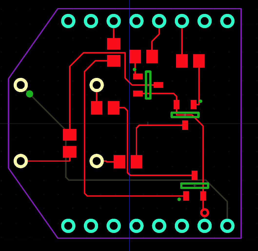

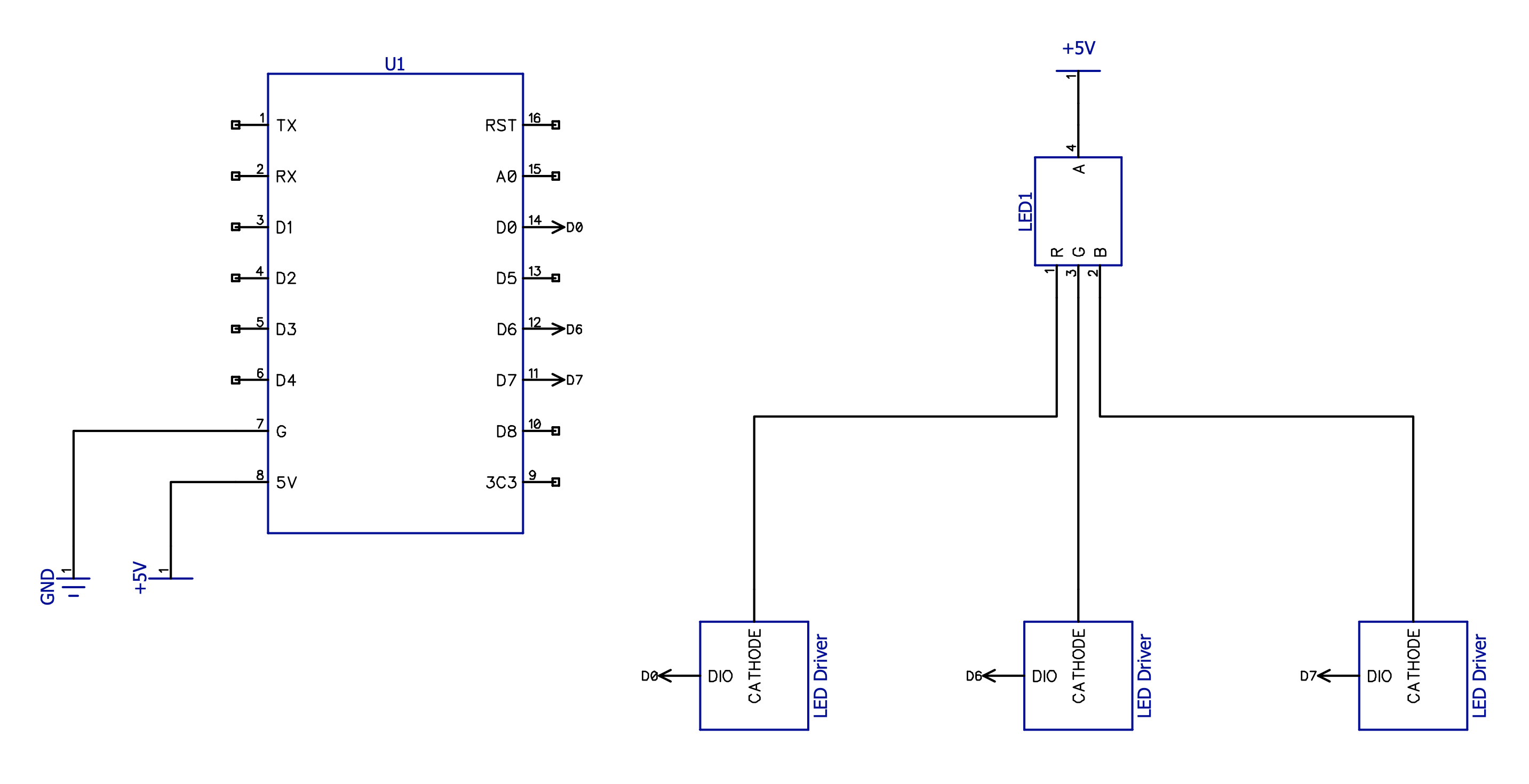
Once I had reached a final circuit design I decided to have it printed on a PCB and assembled on an automated SMT assembly line instead of trying to build it onto strip board. The PCB gives me access to smaller components (such as surface mounted resistors and transistors) and allows me to package the custom electronics in a neater way. The other key benefit is that the automated assembly means that its easy to make larger volumes of PCBs should I ever decide to make more!
The first stage was to translate the schematic into the PCB design software. I choose to use Diptrace as its a package I am familiar with and the pricing structure for hobbyists is very reasonable! Once I have a schematic I can convert it into a PCB. I opted to design the PCB as a “shield” type design so that it can sit over the top of the Wemos D1 in a really compact way. I also avoided adding a copper pour to the board to hopefully avoid blocking any of the wifi signal from the Wemos board.
Instead of using a standard LED footprint I chose to use 4 plated through holes spread out in a square so that the LED could be installed a bit like a pyramid giving it a rigid raised height perfect to put it in the centre of the diffuser.
I chose to use JLC PCB to fabricate the boards and complete assembly as they offered a competitive price and could handle both the board fabrication and assembly while also supplying the required parts. I kept all of the components on one side of the board and used a green solder mask as that is a constraint of the automated SMD assembly process. I also had to select components from the standard library of parts (although the library contains 30,000+ parts so wasn’t much of a limitation for the simple parts I needed!)
The schematics, GERBERS, and pick and place files can all be downloaded from this repo:
DIY Hue Server
To enable centralised control of the lights we will require a server to coordinate them. Since we will be using the Philips Hue framework we can make use of the DIYHue project which provides software to create an imitation hue bridge. We can then connect this hub to a large range of devices. Fortunately the DIY Hue server software can be run on almost any hardware from raspberry pi, to mac, or linux.
In this case I will be running DIY Hue on a Raspberry Pi 3B+ for its low power consumption and low cost but mostly because I have one to hand. Before we can install DIY Hue we need to setup our Pi.
First we need to flash the Raspberry Pi OS (formerly raspbian) which we can download from the Raspberry Pi website:
https://www.raspberrypi.org/downloads/raspberry-pi-os/
Once we have the ISO file we can use BalenaEtcher to easily flash it onto an SD card:
Before we eject the SD card and boot up our pi we may want to enable SSH by adding an empty file titled ssh (no file extension) to our boot directory. This means we wont need to plug a monitor and keyboard in to send commands.
With everything setup we can connect an ethernet cable and power up our pi and let the first boot process complete. Once complete, log in and open the terminal.
First update and upgrade apt-get:
sudo apt-get updatesudo apt-get upgrade
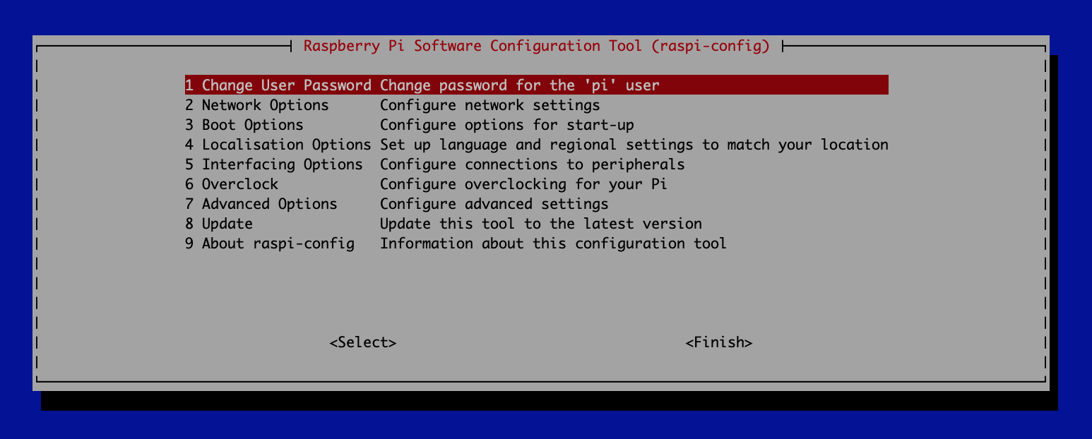
You can now use the raspberry pi configuration tool to set key raspberry pi settings. I recommend setting a new (and secure) password for the ‘pi’ user and expanding the file system to fill your SD card. That can be done with the command:
sudo raspi-config
Once complete, reboot the pi when prompted.
DIY Hue is easy to install with one command in the terminal:
docker run -d --name "diyHue" --restart="always" --network="host" -e MAC='XX:XX:XX:XX:XX:XX' -v '/mnt/hue-emulator/export/':'/opt/hue-emulator/export/':'rw' diyhue/core:latest
With the DIY Hue software installed and running we can now connect to the hub with our phone and the Philips Hue app. When prompted to “press the button” on the hub click the activate button at:
http://{IP_ADDRESS}/hue/linkbuttonWe can now add bulbs and control them all from our phone! First we will need to flash them with some firmware and assemble them.
Firmware
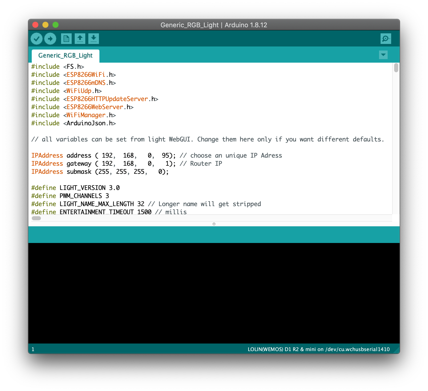


Before soldering the custom PCBs to the Wemos D1 I suggest flashing the firmware. Doing this before soldering them will let you find any boards that are dead out of the box! (of which I had 1!).
The DIY Hue project has a set of firmwares which come with a webGUI and all the required settings and code we need available for different types of devices. Since we are using a simple RGB LED we can make use of the “Generic_RGB_Light” firmware which can be found in the “Arduino” Folder. You can find the firmware here:
https://github.com/diyhue/Lights
To flash the firmware we will need a USB Type B cable to connect the board to our PC and the Arduino IDE which you can download here:
https://www.arduino.cc/en/Main/Software
Before we can upload code to the Wemos D1 board we need to install a board package to our Arduino IDE. Since the ESP Library isn’t a standard Arduino library we will first have to add an additional url to board manager which can be done in the preferences page. We need to add:
https://arduino.esp8266.com/stable/package_esp8266com_index.json</a>
Once we have added that url we search for and install the ESP board profile from the arduino boards manager. Set the board settings as per the image above and select the correct port. We are now ready to upload!
Download and open the firmware file. From here you can choose to enter your Wifi network credentials and LED pin outs so that the board automatically connects but we dont need to make any changes here as we can access all of these through the web UI and edit them during runtime!
Once you're ready, hit the upload button!
Note: Some Wemos D1 boards use a CH340 USB to serial converter which in later versions of macOS causes a kernel panic when plugged in! If you find you're having this issue you will need to update your drivers. More info can be found here: https://thingsmatic.com/2017/08/07/using-ch340-de…
Once the firmware is flashed you can connect to the wireless access point that the board creates to enter your wifi credentials and you can also set the correct pinouts for the board. These will vary depending on how you soldered your LED but they will always be a combination of pins 12, 13, and 16.
Assembly


Now we have all the parts its time to assemble the boards into a finished lamp!
First solder the RGB LED to the custom PCBs. There should be a white dot on the silkscreen that indicates which hole the anode must be connected to. It doesn’t matter which hole the other legs go in since we can adjust the colour channels in the software. Being consistent will make it quick work though!
Next we need to solder header pins to the Wemos boards. A neat trick to help get the header pins straight in your PCBs is to press the headers into your breadboard and solder the board on the breadboard. This way you know that the mating part will fit on! With the header pins installed drop the LED PCB over the top making sure you get it the right way up and solder it on.
Since the Wemo D1 doesnt have any mounting holes I used hot glue to secure them into the printed piece. The hot glue will fill any gaps and hold the board firmly but dont go overboard as too much could cause the electronics to overheat!
Finally I glued the diffuser cube on the top using a small dab of hot glue in each corner. The hot glue holds the diffuser firmly but it can be broken off with a little force incase you need to adjust the angle at all (which I had to do a few times!). Just be careful not to damage the LED inside.
Setup the Lights


With the lamps built, the firmware flashed, and a connection made to the wifi the final step is to add them to the server through the Philips hue app. This is easily done with the “add light” button and the server should automatically pick them up. You can now control the colour of the lamps through the app.
To enable Light syncing with our TV or PC we need to create an entertainment zone. To do that select:
Settings -> Entertainment Areas -> Create Entertainment Area.
In this screen we can tell the app which lamps to include and can also place them around the space using by dropping their light icon into the right place on the picture. Tapping the lamps changes the height at which they are set.
To connect your Philips TV you need to now select the entertainment zone under the ambilight+ settings.
To connect your PC download the hue sync app and click “Start Sync”
Enjoy!

Thank you for reading my Instructable, I hope you enjoyed it! The lamps turned out much better than expected! Im really pleased with how they look and the light sync makes watching films and playing games immersive as the room lights up to set the scene. I would like develop the lamps further and remove dependance on the Philips hue protocol so that HDMI input to the pi to be used to drive the lamps. I would also like to introduce HomeKit control so that the lamps can be used as smart lamps when not light syncing.
I hope this Instructable has been interesting and inspired you to create your own lamps. I found the project to be a huge learning experience but one that I enjoyed, and I certainly picked up a lot of new skills along the way. If you build these lamps please leave a comment - I’d love to see what you make!