Ready to Drive System

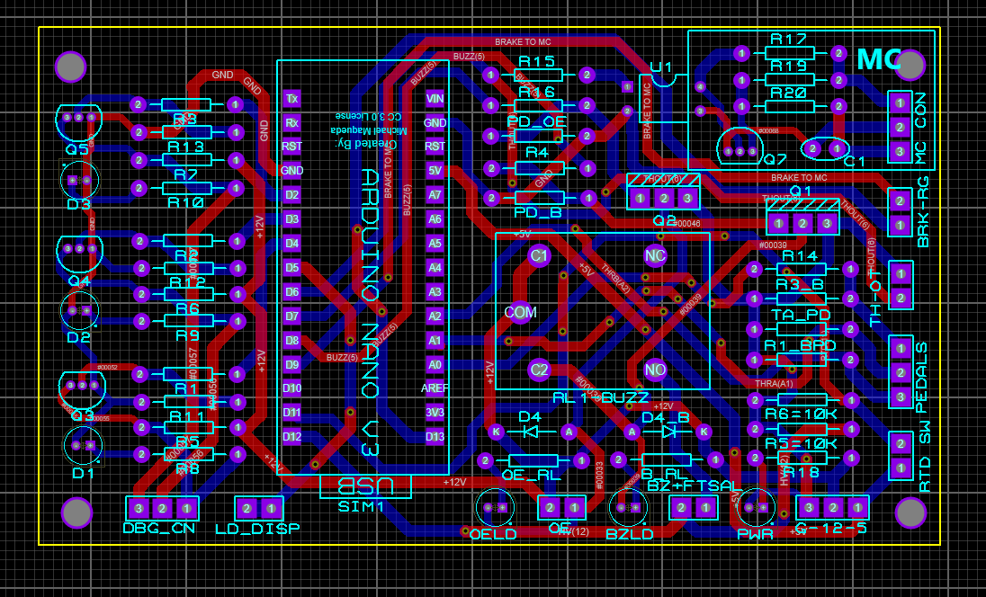
The RTD-system will check the conditions that whether the tractive system is active or not. These signals are provided to a microcontroller which in turn sends the enable signal to the motor controller using a relay and operates a buzzer, having a sound intensity of ≥90 dB, for 3 seconds. Brake system encoder and Ready-to-drive mode, along with APPS, are implemented on an Arduino microcontroller.
Supplies
Arduino Nano Microcontroller
Transistor (IRF 540, 2N7000)
Resistors (10K, 560, 470, 3K)
Relay
Optocoupler
Parts of Circuit
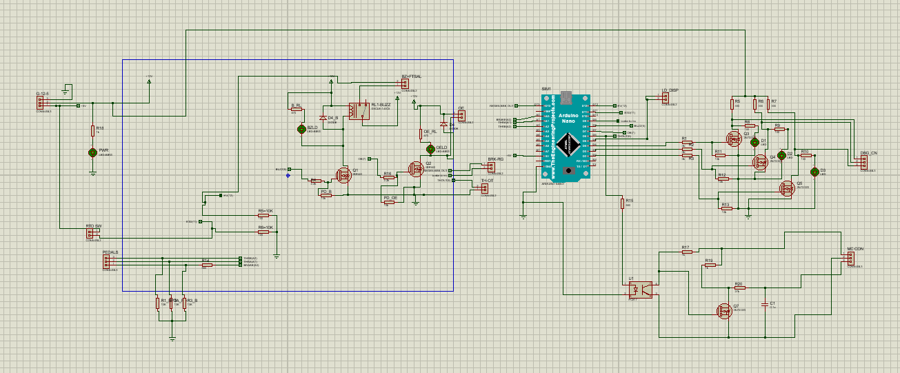
To activate “Ready to drive mode” the driver must follow a sequence of additional actions. These actions include pressing the brake pedal and a dedicated “RTD Button” Brake pedal signal referring to the pressed brake is provided by the brake system encoder. After performing these two actions, the system checks the conditions if the tractive system is active or not. This signal is generated by the TSAL circuit which sends high logic in the case of a deactivated TS and vice versa. These three signals are provided to a microcontroller which in turn sends the enable signal to the motor controller using a relay. Brake system encoder and Ready-to-drive mode, along with APPS, are implemented using an Arduino Nano microcontroller, which in turn sends a high logic to Transistor Q1 causing an operational relay and operates a buzzer, for 3 seconds. APPS values are mapped and sent to the motor controller through an optocoupler for isolation. These signals are monitored by the microcontroller and in case an error occurs, enable signal is not sent to the motor controller and the respective debugging LED on the dash is turned ON.
Reference
EV4.11.6 The vehicle is ready-to-drive as soon as the motor(s) will respond to the input of the APPS
EV4.11.7 After the TS has been activated, additional actions must be required by the driver to set the vehicle to ready-to-drive mode (e.g. pressing a dedicated start button). The transition to ready-to-drive mode must only be possible during the actuation of the mechanical brakes and a simultaneous dedicated additional action
EV4.12.1 The vehicle must make a characteristic sound, continuously for at least one second and a maximum of three seconds while entering ready-to-drive mode.
Ordering the PCBs
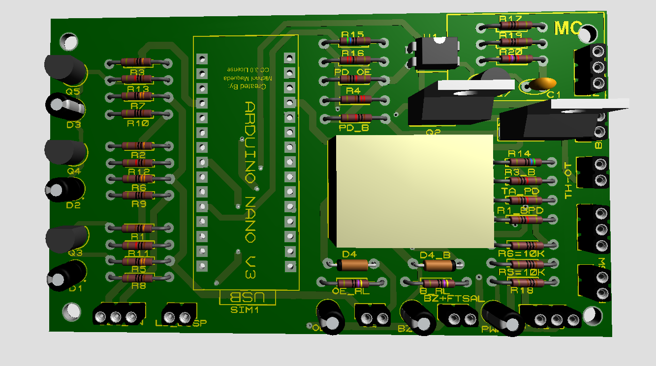
Now we have got the PCB design and it’s time to order the PCB’s. For that, you just have to go to JLCPCB.com, and click on the “Order now” button. JLCPCB has sponsored this project. JLCPCB (Shenzhen JLC Electronics Co., Ltd.), is the largest PCB prototype enterprise in China and a high-tech manufacturer specializing in quick PCB prototype and small-batch PCB production. You can order a minimum of 5 PCBs for just $4.
To get the PCB manufactured, upload the Gerber file you downloaded in the last step. Upload the zip file or you can also drag and drop the Gerber files.
After uploading the zip file, you’ll see a success message at the bottom if the file is successfully uploaded. You can review the PCB in the Gerber viewer to make sure everything is good. You can view both the top and bottom of the PCB.