Real-Life Sim Racing: Drive an RC Car With a Gaming Wheel
by Alex595 in Circuits > Remote Control
384 Views, 2 Favorites, 0 Comments
Real-Life Sim Racing: Drive an RC Car With a Gaming Wheel
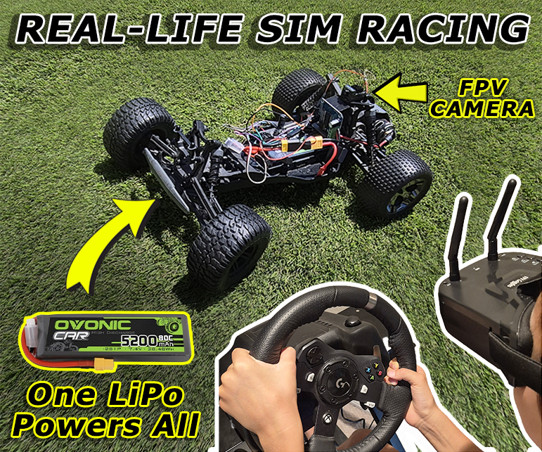
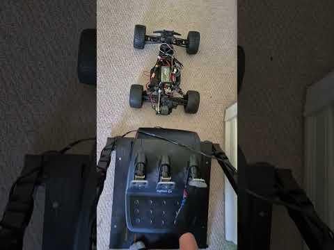
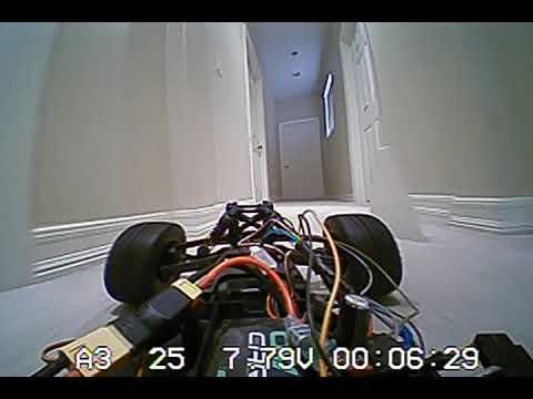
Have you ever been controlling an RC Car and thought to yourself, "What if I could drive this like a real car?"
Hi, my name is Alex. I am a 15-year-old student in Orange County, California. I have always loved electronics, from soldering to programming, and I want to pursue a career in engineering.
In this project, I turned my RC car into a real-life racing simulator. Using FPV goggles, I can see from the driver's perspective and steer the car with a real racing wheel and pedals. I made the controls as intuitive as possible; the gas makes it go forward, and the brake makes it go backward.
One 2S LiPo battery powers all the components, making it much lighter than using separate batteries for the motor and 5V electronics. To make the communication responsive and reliable, I used ESP-NOW. This project also contains multiple safety measures, such as a 30A fuse, 1000μF capacitor, and software failsafes.
The software reads wheel and pedal inputs on the PC, then a transmitter ESP32 sends the data wirelessly to the car via ESP-NOW.
Note: This conversion only works with a brushed motor since the code and wiring specify an H-bridge motor driver, not the brushless ESC necessary for a brushless motor.
So let's get started!
Supplies
This is a list of the parts for the project and links to buy them.
- Gaming Wheel & Pedals
- Brushed Motor RC Car (I used the ECX AMP MT, it is discontinued now, but any car with a 7.4V brushed motor and 5V servo works)
- 2S 5200mAh 80C LiPo Battery
- ESP32 Dev Boards
- UBEC Module
- BTS7960 Motor Driver
- XT60 Pigtail
- 14AWG Fuse Holder
- 30A Fuses
- 25V 1000uf Capacitors
- Servo-style power splitter
- FPV Camera and Goggles
- Dupont Wires
- Double-sided foam tape
- Soldering Iron
All code files are available on GitHub
Car Hardware Overview
.png)
To power the entire car with a single 2S LiPo battery, I created this layout. The first wires that touch the battery are from a low-current power splitter that powers the FPV camera directly with 7.4V (the camera is meant to run on 7.4V), and a UBEC. This converter outputs 5V, which is safe for the motor driver logic, ESP32, and servo. Since the ESP32 is pulling from the same source as the servo, a 1000μF capacitor is soldered across VIN and GND (This keeps the ESP32 power steady if the servo pulls a lot of voltage). After the low-current splitter, a 14AWG XT60 pigtail with a 30A fuse is attached to the main battery line. This fuse is at a high enough amperage to not blow when the RC car is racing, but low enough to protect the wires from melting. This high-current power is supplied to the motor driver's battery input, which powers the car's drive motor.
Software Overview
.png)
To make my real-life sim-racing experience, I used this workflow. The first layer of software is a Python script that reads the wheel and pedal inputs of my gaming setup and sends the information over Serial to an ESP32 board plugged into the computer. This ESP32 acts as a post office, and simply packages and transmits the data, except this time it is sent wirelessly over ESP-NOW. Finally, on the car, an ESP32 listens for these packets, turns the servo to match the wheel, and spins the motor accordingly. Throughout these layers, there are multiple safeguards in case of connection loss. In the Python script, if no pedals are pressed, it shifts into a "neutral gear" and sets the throttle to 0 to ensure it will not spin erratically. Furthermore, both Arduino layers have timeouts so that if they stop receiving data for 500ms (in the event of the wheel, PC, or transmitter unplugging), they stop the car and set the servo straight and shift into the neutral gear.
Replacing Motor Driver
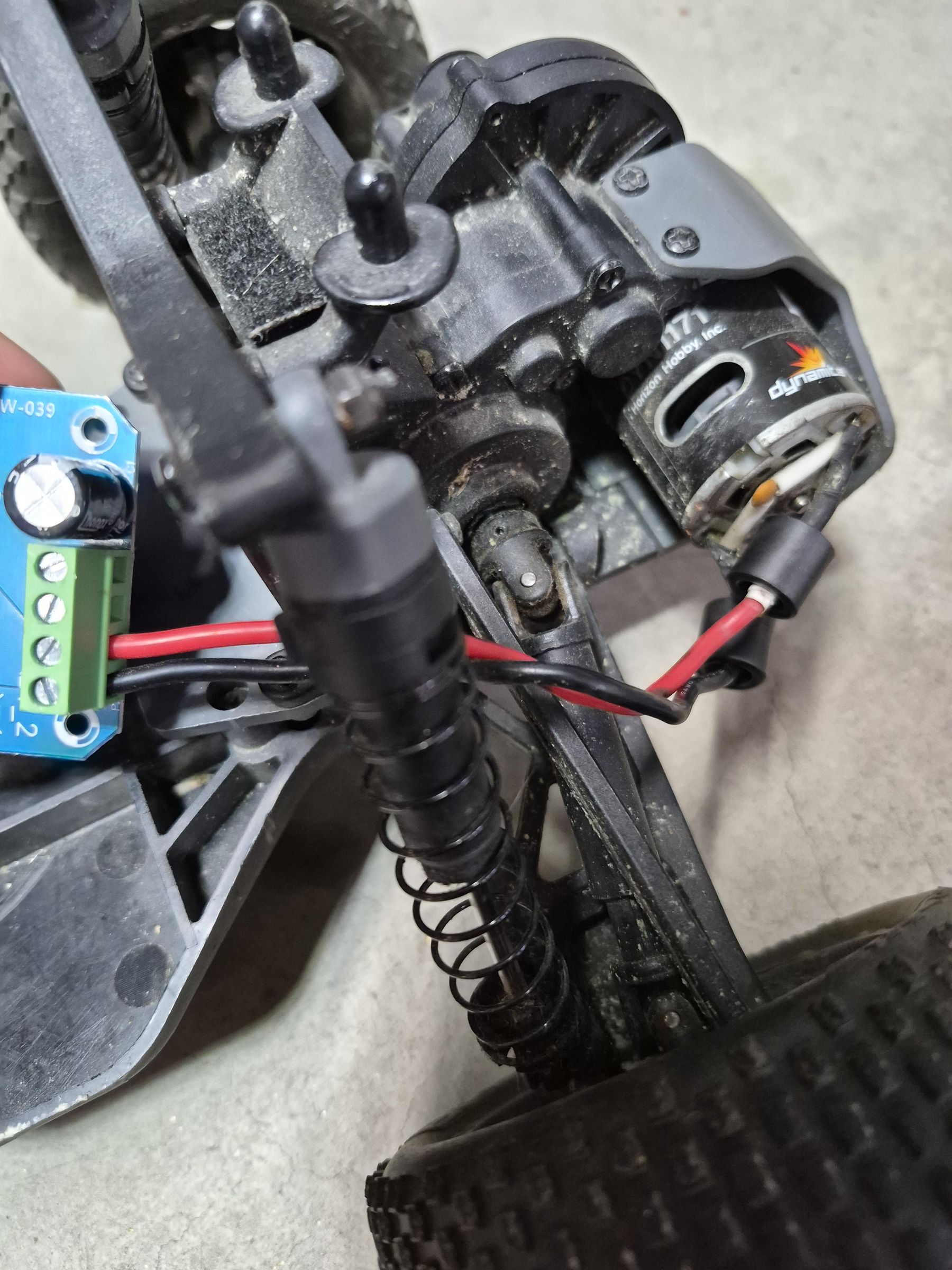
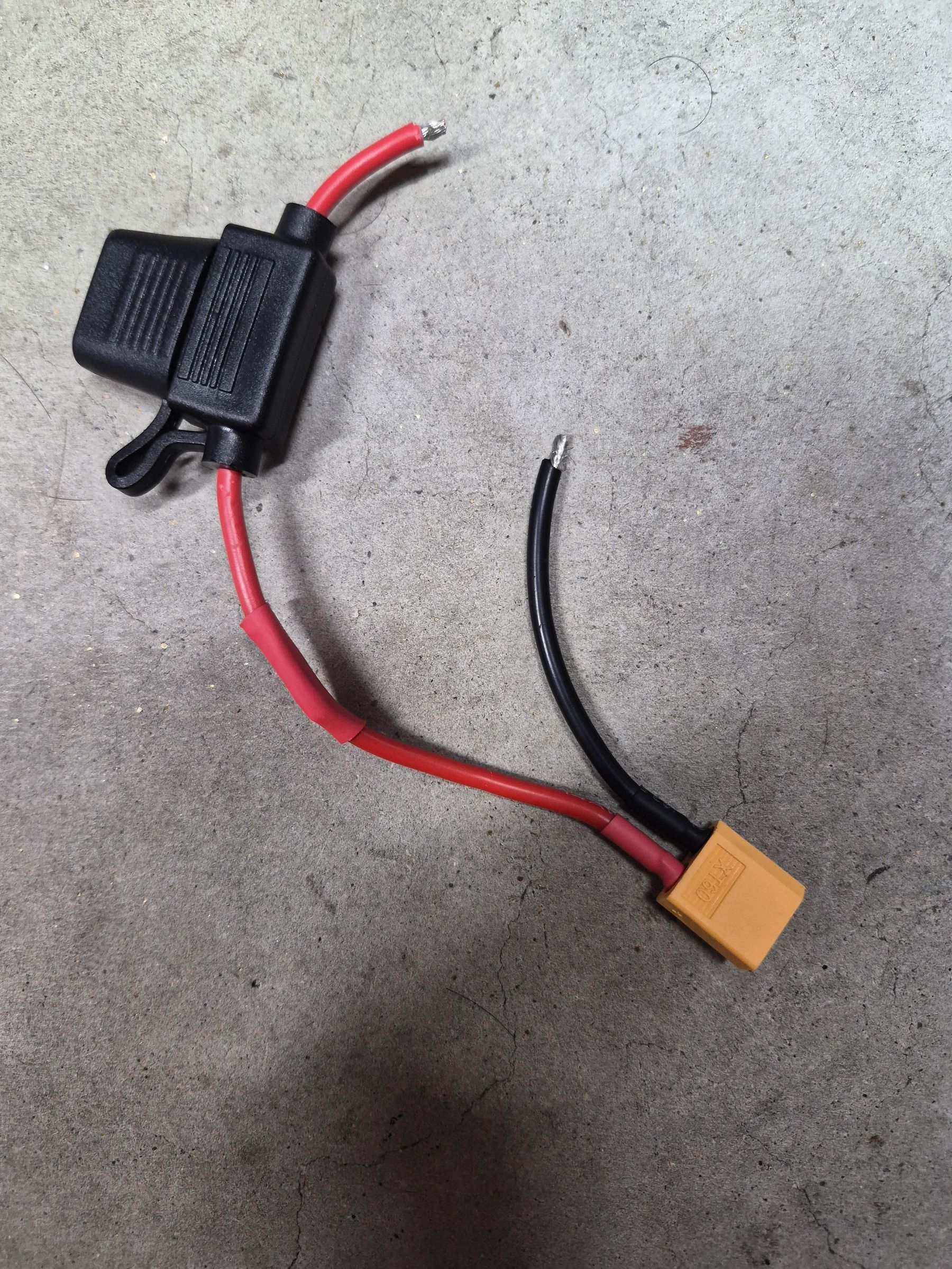
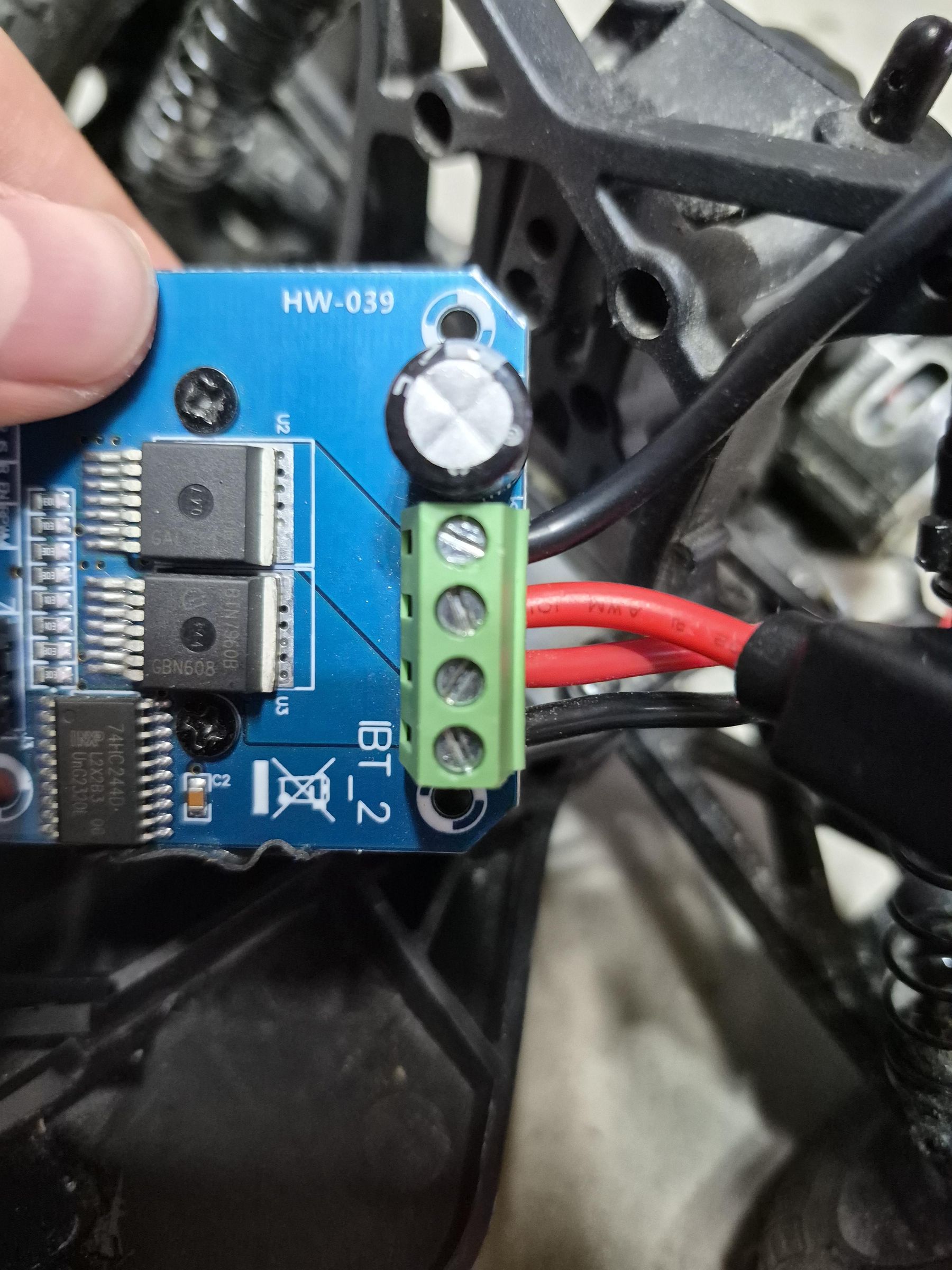
To begin, remove the existing speed controller and receiver from the car. Then you can place the BTS7960 into the chassis using double-sided foam tape. Cut off the banana plugs or other adapters of the motor wire to reveal bare wire, which you need to insert into the BTS7960 Motor Output slots. Now, solder the 14AWG fuse holder to the red wire of the XT60 pigtail and screw the pigtail into the correct battery input terminals.
Getting 5V Power
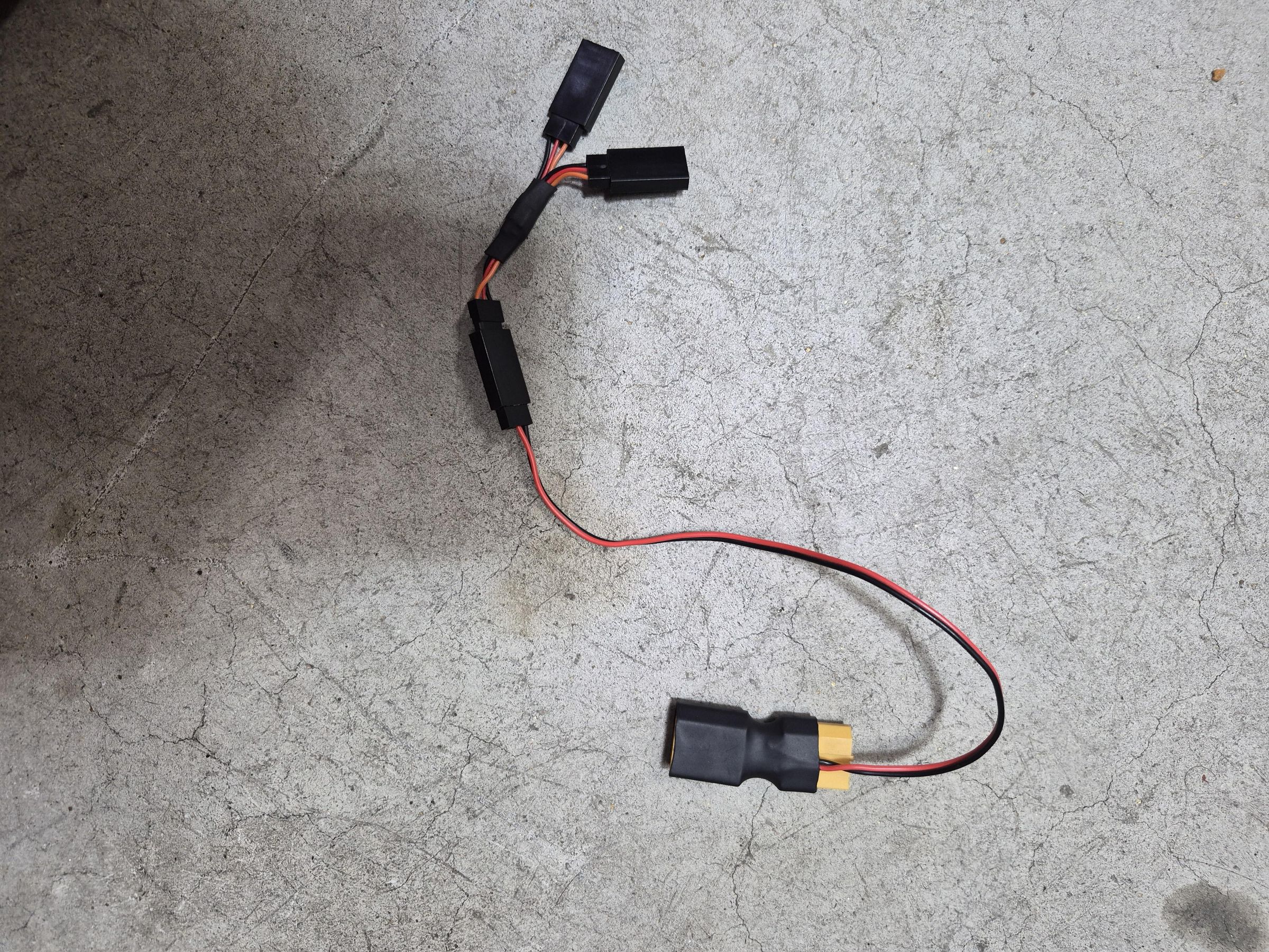
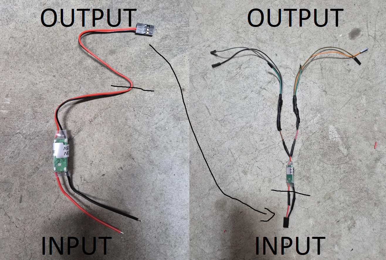
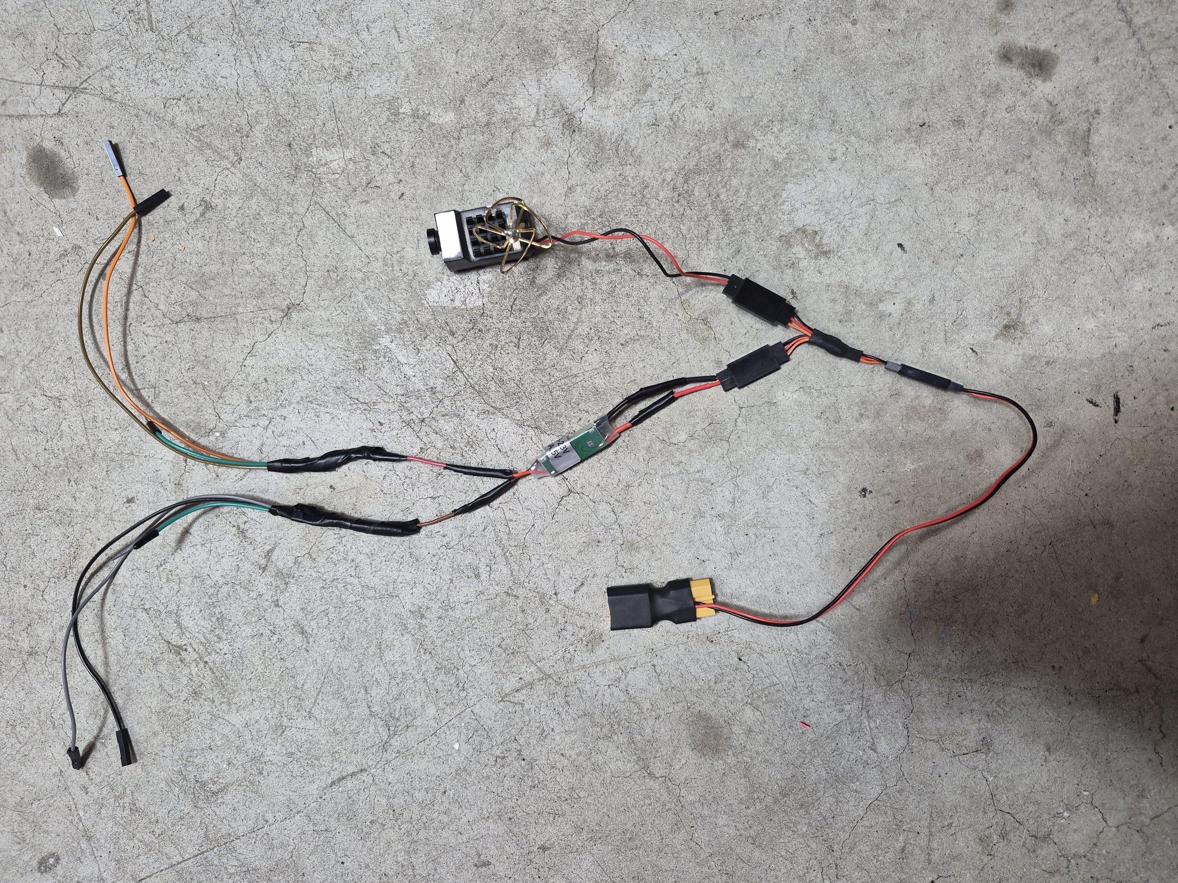
Using the XT60 to servo-style power adapter that comes with the FPV camera, connect the servo Y-splitter to it. Now one of the outputs can be used for the FPV camera, and the other will be converted to 5V using the UBEC. To power the UBEC, we need to flip the black servo-style power output to the input wires. And once that is soldered on, you need to solder one male and two female Dupont wires to each UBEC output wire. The male pins power the servo, one set of female pins connects to the BTS7960 VCC and GND for 5V logic, and the last pair of female pins powers the ESP32 via VIN and GND. All components can be secured to the chassis with double-sided foam tape.
Adding the ESP32
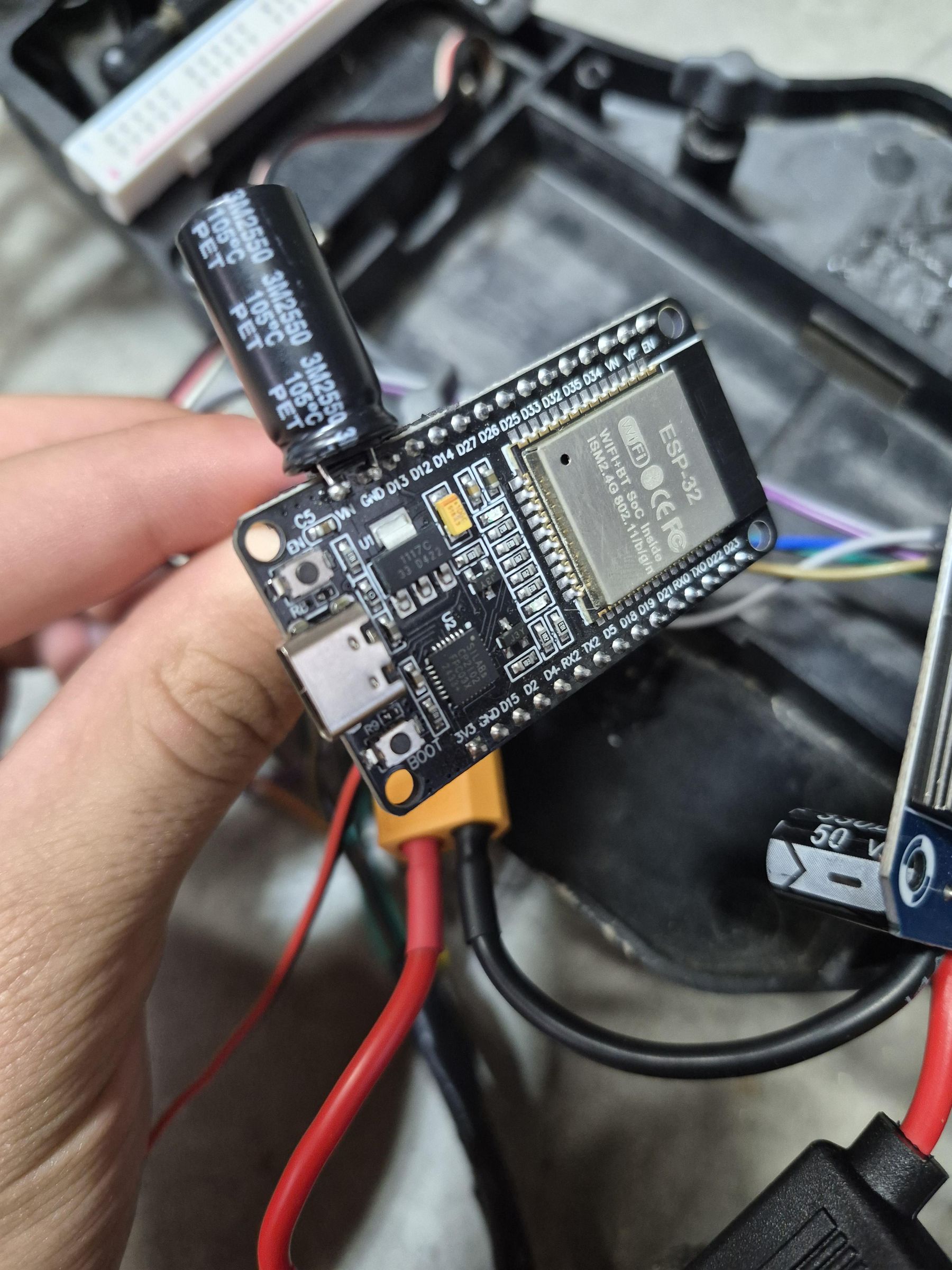
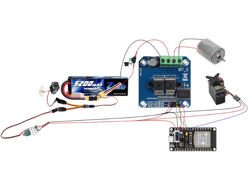
First, carefully solder a 25V 1000μF capacitor across the ESP32 VIN and GND pins and ensure that it is soldered with correct polarity (because incorrect polarity can make the capacitor burst). Now you can wire the motor driver and servo pins to the ESP32 for control. Connect the pins as follows: BTS7960 R_EN to ESP32 D27 pin, L_EN to D14, RPWM to D12, LPWM to D13, and servo signal to D26. Be sure to attach the ESP32 to the car body with foam double-sided tape.
Note: Once the code is uploaded and everything is running, if the motor won't spin, you may need to use a 3.3V to 5V logic level shifter to boost the voltage for the BTS7960 control pins. But this is likely unnecessary since most drivers already accept 3.3V.
Now that the hardware is done, we can program!
Finding Wheel Mappings
In my Python script, I use the mappings for the Logitech G920 where axis 0 is steering, axis 1 is gas, axis 2 is brake, and axis 3 is clutch. So, if you have a different wheel, run the find_wheel_mappings.py script to find your mappings.
Reading the Wheel
This file is on GitHub as read_wheel.py. To get started, install and import the following packages in Python:
Now we initialize pygame and set up the wheel.
Next, we open the serial port. Remember to replace COM5 with the COM port of your ESP32.
Then we loop that reads the values, packages, and sends them.
Find Receiver MAC Address
Upload this code to the receiver ESP32 and write down the given MAC Address. This address makes the ESP32 send to the specific receiver. The code is on GitHub as FIND_MAC_ADDRESS.ino.
ESP32 Transmitter
The transmitter is simply an ESP32 that has the code flashed to it, plugged into the computer running the Python script. The code is on GitHub as PC_TO_CAR_ESPNOW_TRANSMITTER.ino. In the Arduino IDE, we need the libraries: esp_now and WiFi.
Then we set the MAC address that the transmitter is sending to, the variables, and the OnDataSent function. Remember to put your receiver MAC address into the broadcastAddress variable.
Then, in setup, initialize ESPNOW and Serial.
Finally, in the loop, listen for new Serial data, and save it. And add a timeout failsafe so that if Serial stops sending, the ESP32 will send idle values to the car, making it stop moving.
Car ESP32 Receiver
The receiver is the ESP32 on the RC car, and it listens for the packets sent from the transmitter and executes them physically via servo and motor driver. The full file is on GitHub as RCCAR_ESPNOW_RECEIVER.ino. In the Arduino IDE, we need the libraries: ESP32Servo, esp_now, and WiFi.
Then we can create the variables, the packet struct, and the onDataRecv function.
Now in setup, we set the pins, set up ESPNOW, and reset all variables.
In the loop, we read the new values and move the servo and motor accordingly. A timeout failsafe is also included to stop the car if the ESPNOW connection is lost.
Drive!
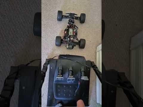
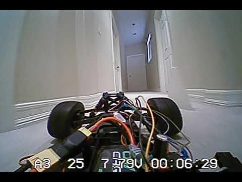
To get the car running, connect the ESP32 transmitter to the computer, ensure no app is using the port, run the Python script, and finally power the car with the LiPo. Congratulations, you made a Real-Life Sim Racing Car powered by only one LiPo Battery! Have fun!