Relay-based Ignition Coil Driver
by ninetyphase in Circuits > Electronics
99 Views, 0 Favorites, 0 Comments
Relay-based Ignition Coil Driver
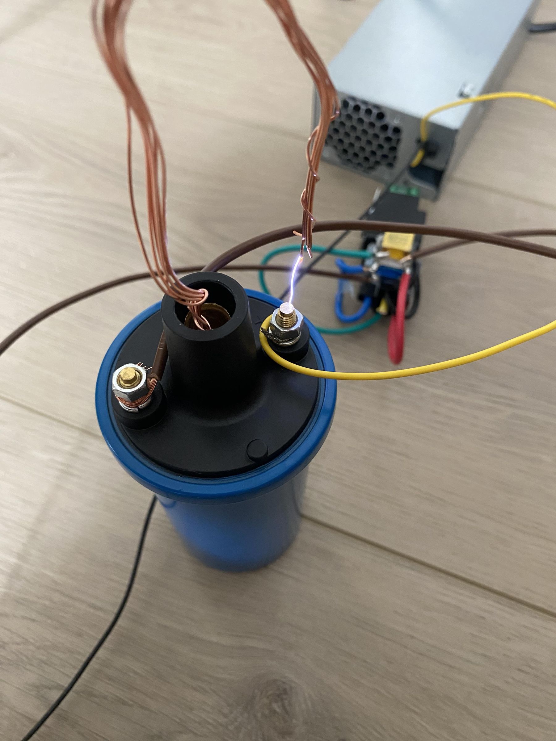
Hello, today we are going to make a "Relay-based Ignition Coil Driver" An ignition coil is used to ignite the fuel-air mixture inside a car engine by using a 12V input and switching to create a high-voltage spark and a quick spark occurs for a short time. In this project we will use a relay and a capacitor to make pulsed DC to drive the ignition coil. The relay will oscillate the current on and off, which will output awesome arcs!
Supplies
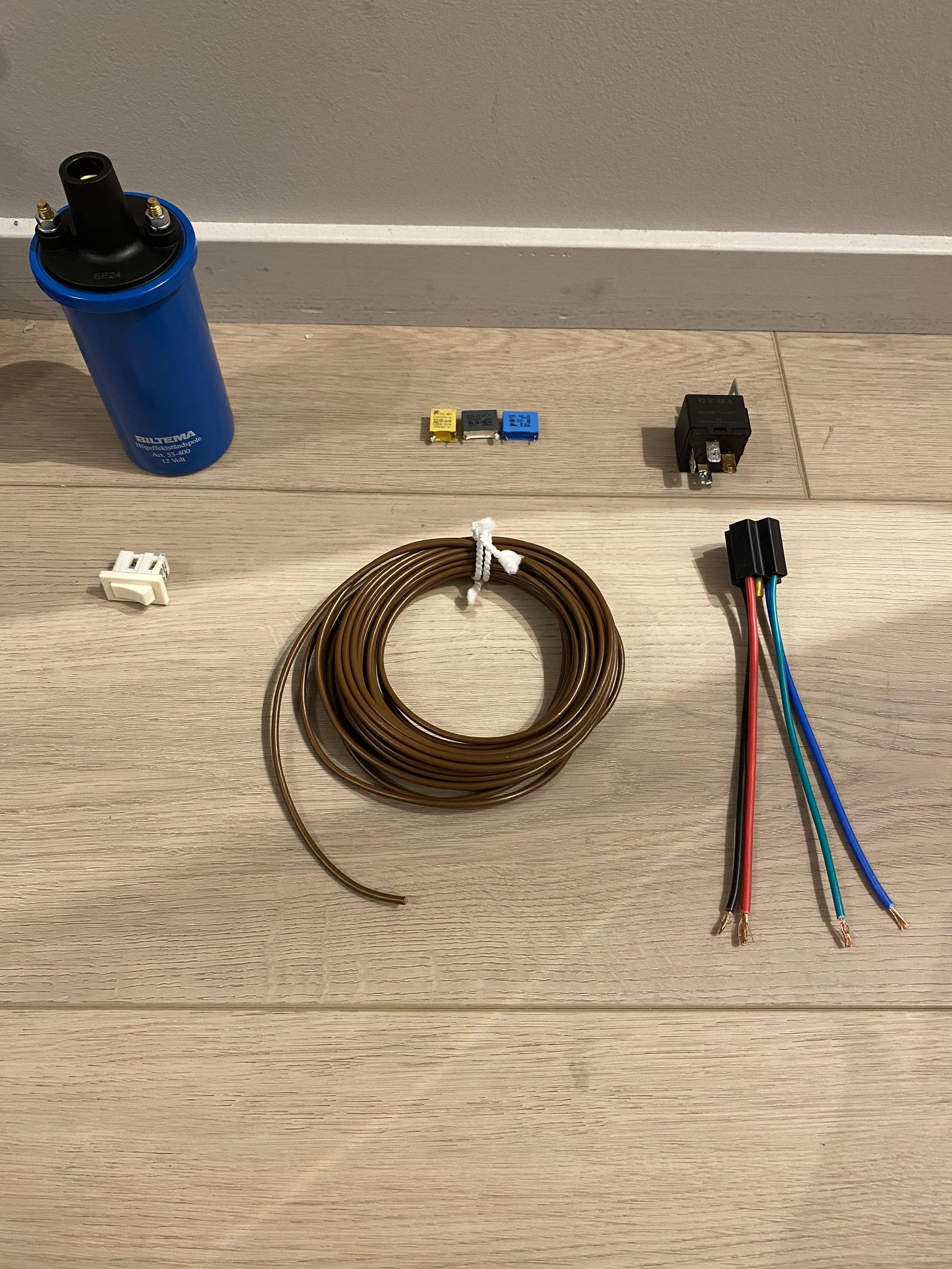
Part list:
Ignition coil {preferably oil-filled coils}
Automotive relay SPST {normal small relays will self-destruct}
Relay socket {to change the relay if it's destroyed}
1μF film capacitor or safety film x2 capacitor {must be film caps/safety film caps because electrolytics will vent/fail}
A switch {to turn on and off the driver}
Some wires {to wire things}
And some hot glue to glue the things together for easier soldering.
---------------------------------------------------------------------------------------------------------------
Tools list:
Soldering iron.
Multimeter.
Hot glue gun.
Hot glue sticks.
Wire cutters.
Wire insulation stripper.
12v at least 10a power supply to leave some headroom.
Schematic
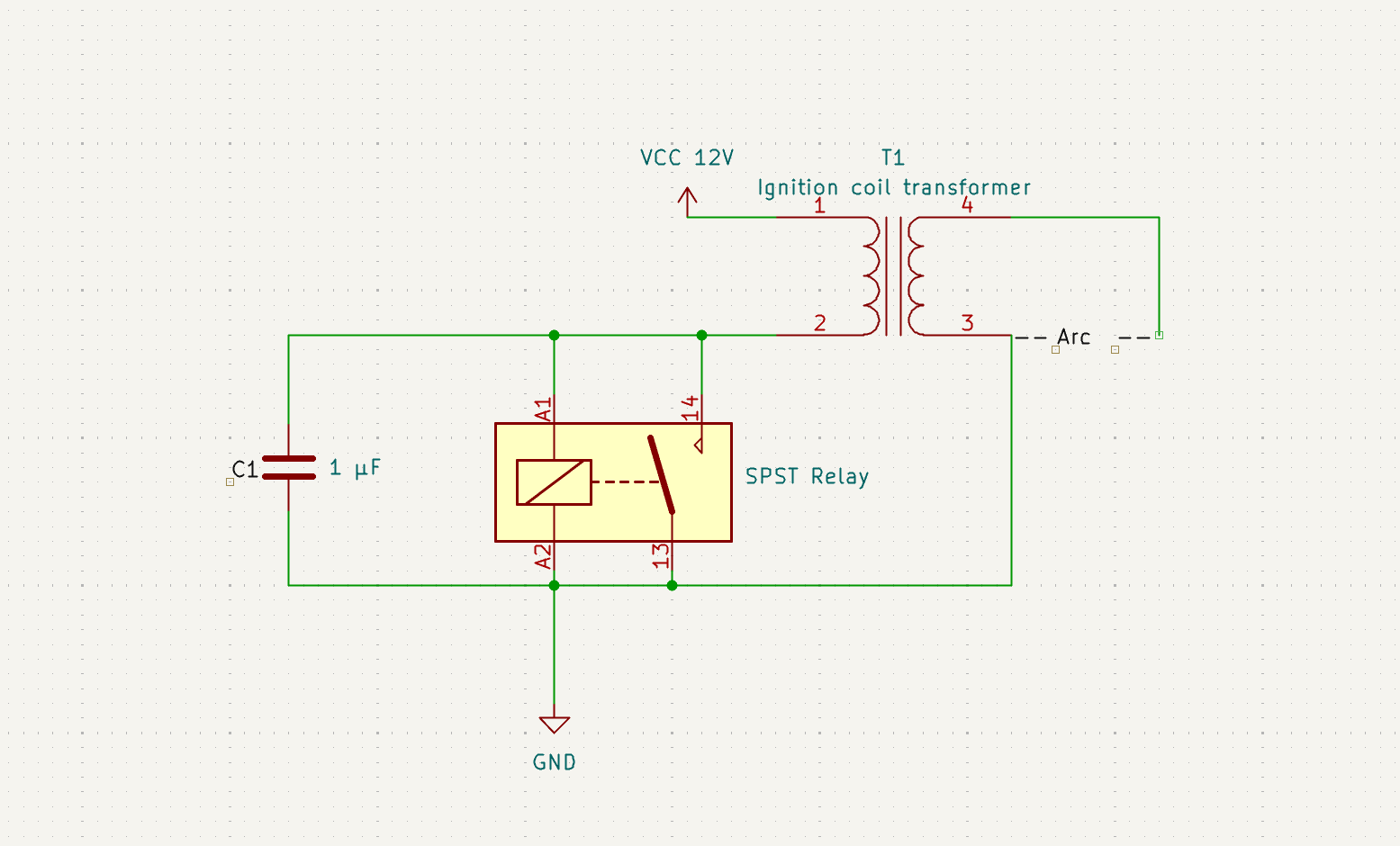
Here's the schematic for the driver. The capacitor slows down the relay switching to prevent burning and controls the timing. the relay is wired to repeatly switch on and off rapidly. This creates a pulsed DC current through the ignition coils primary. When the current is interrupted the magnetic field inside the ignition coil collapses and creates an visible arc from the central hole to ground.
Building Process
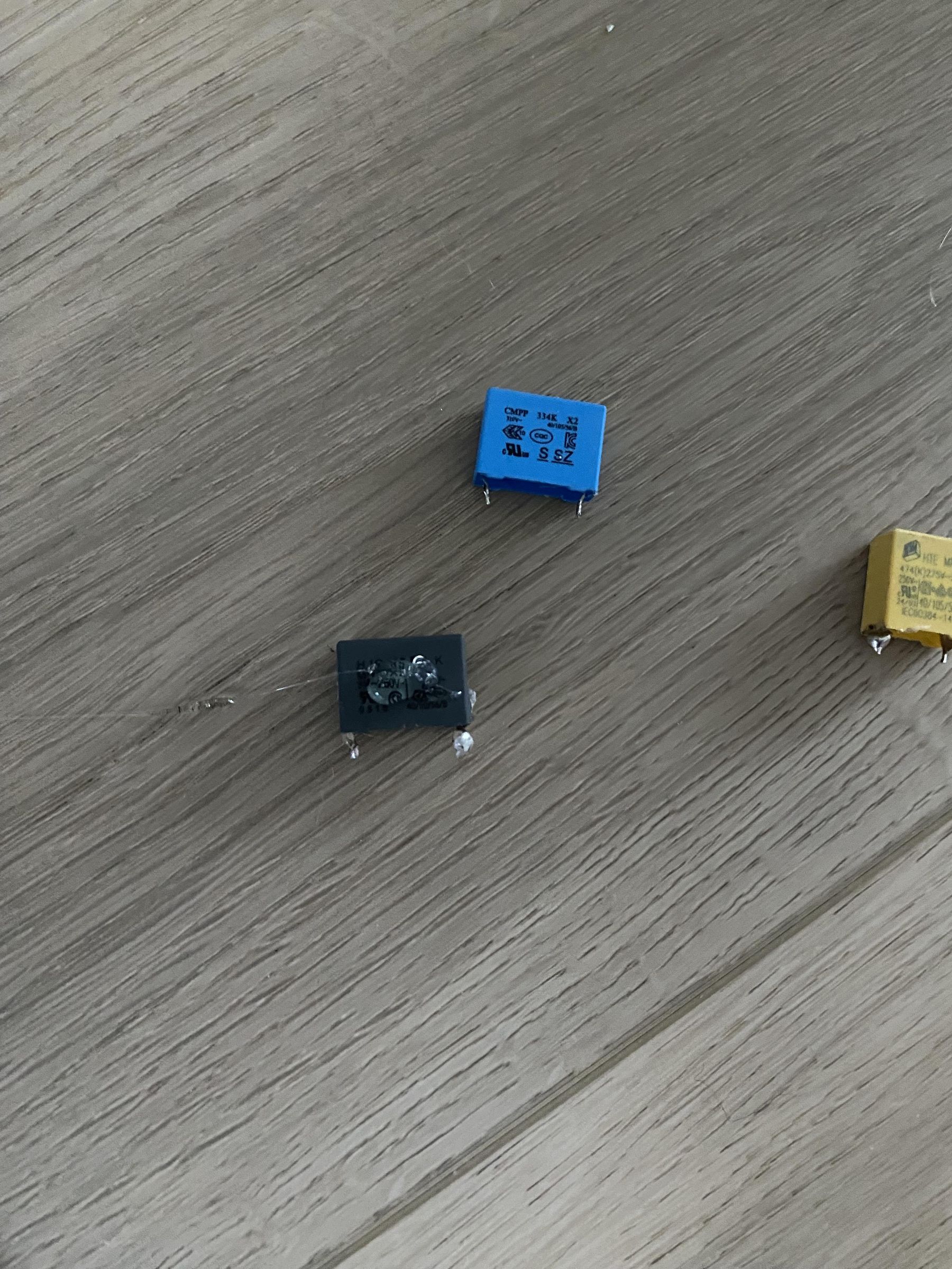
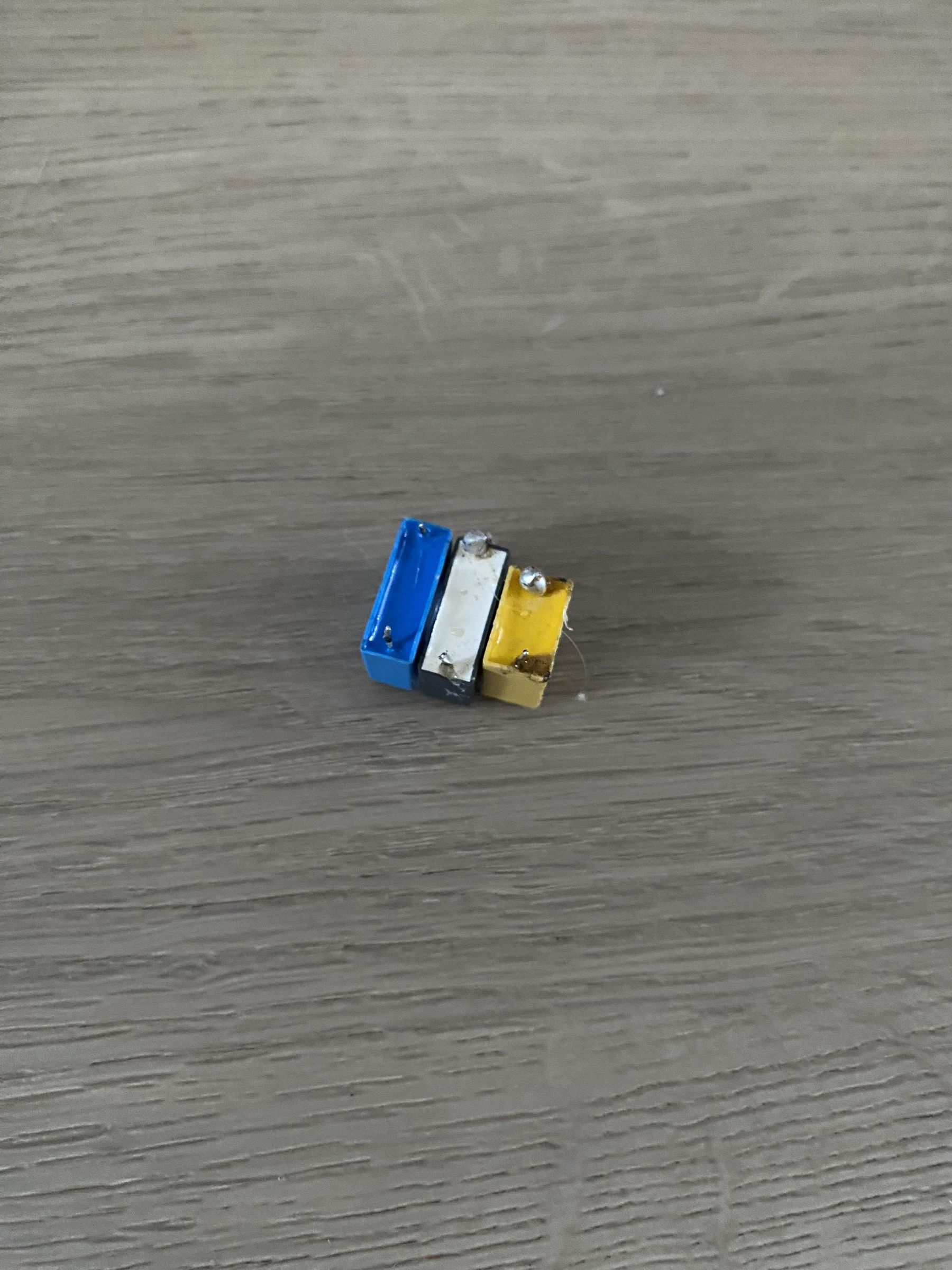
Lets begin building! First I don't have 1μF capacitors so I will put 3 safety film capacitors in parallel to gain 1.02μF from 0.47μF, 0.33μF and 0.22μF. Now I am going to glue them together in parallel and solder them together.
Gluing the Capacitors on the Relay Socket
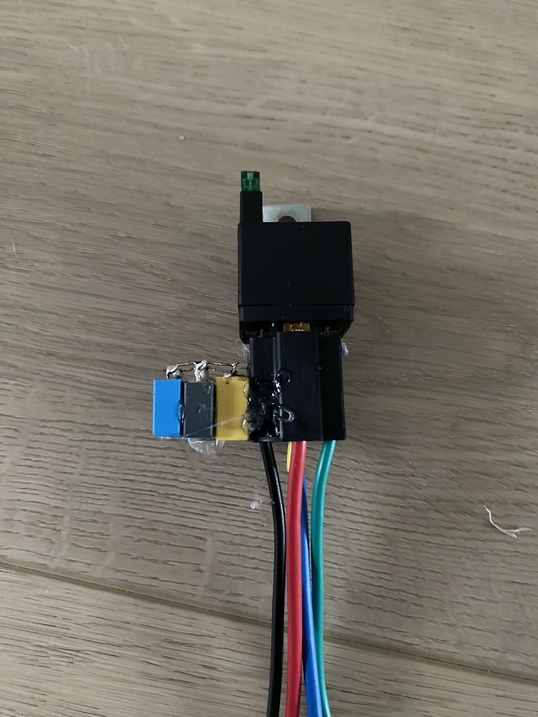
Glue the capacitors to the sides of the relay socket.
Wire Everything
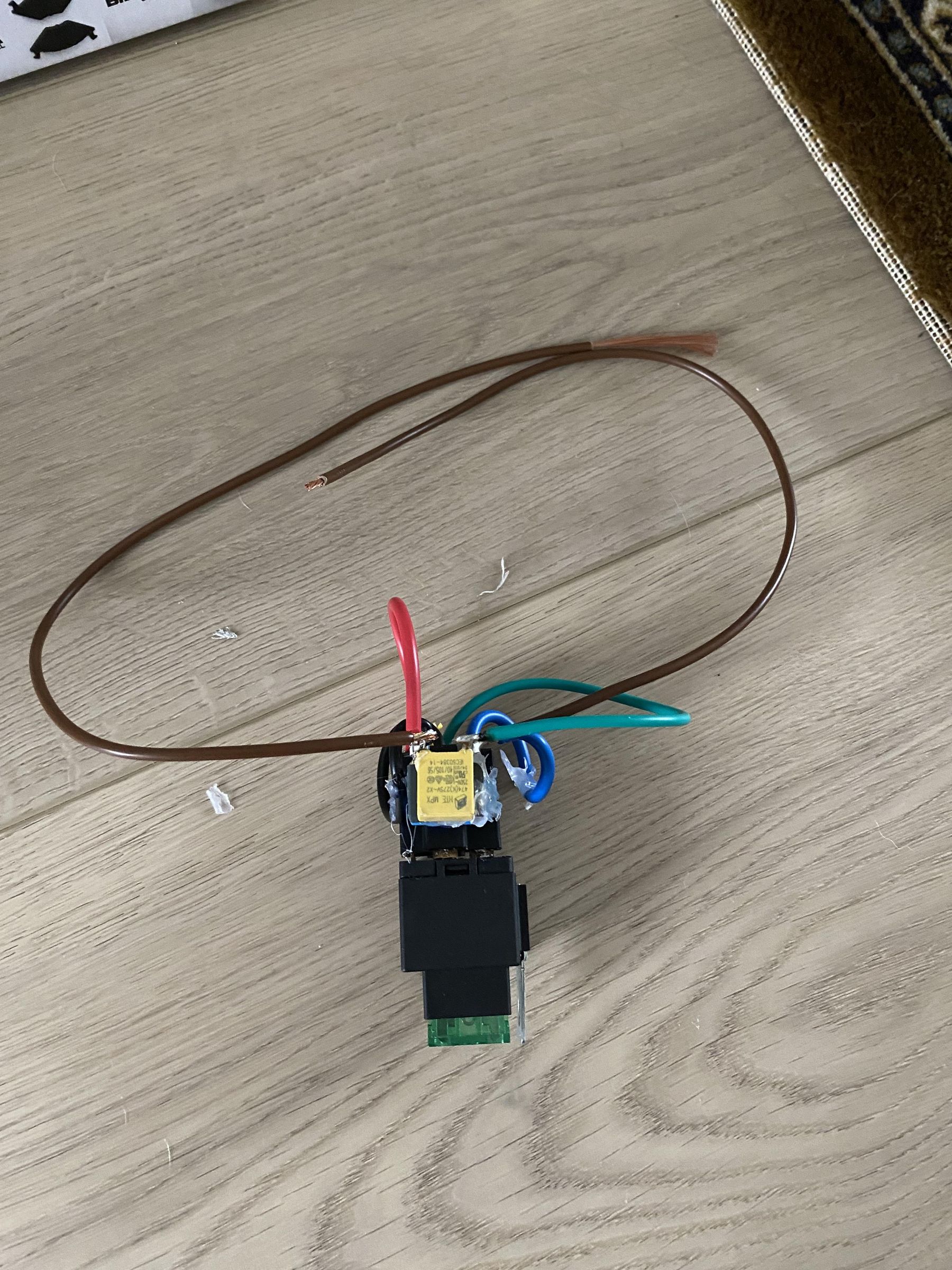
Now lets wire everything according to the schematic.
Test It Out!
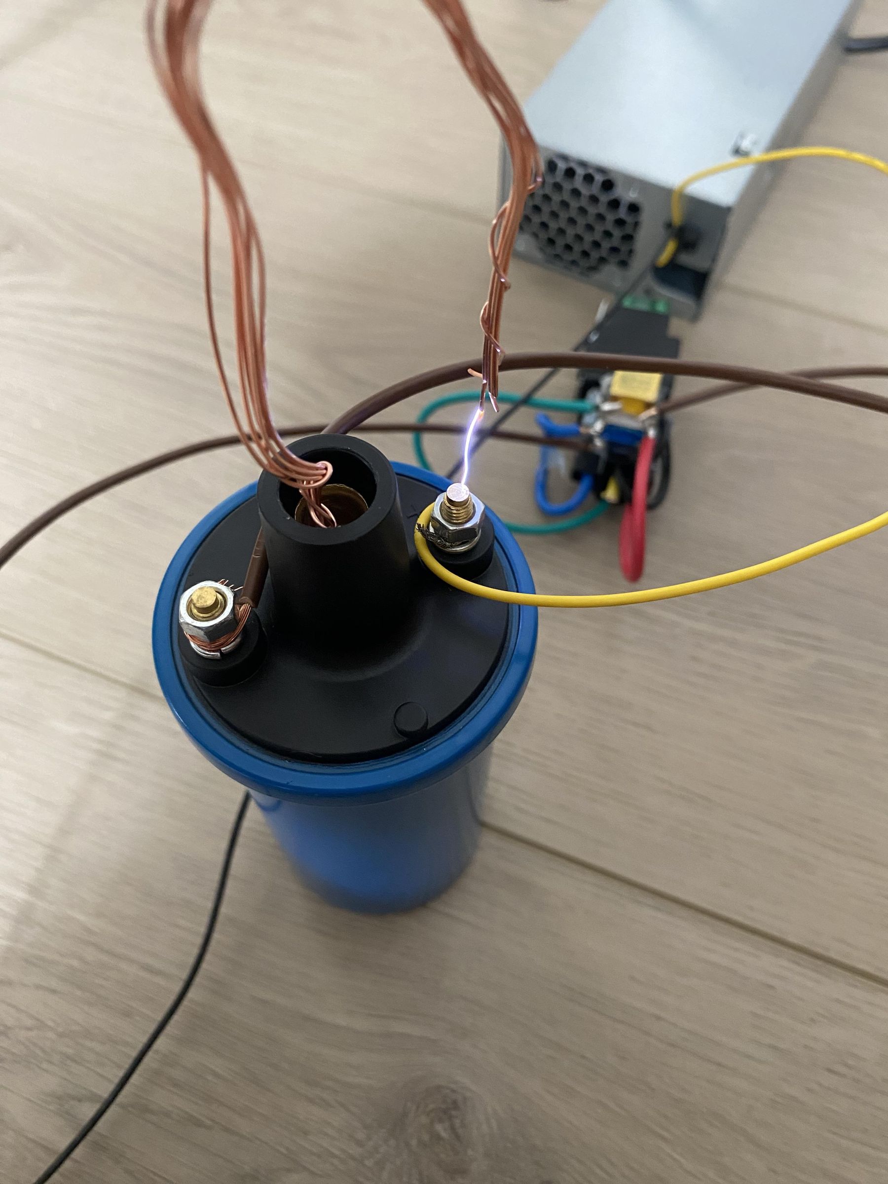
Connect + to + to the ignition coil, ignition coil driver needs gnd from the power supply and on the other gnd from the driver goes to the ignition coil, and WOW! it outputs amazing arcs! and now you got a ignition coil driver with only a relay and capacitor!