Remote Camera Shutter Using Recycled PCBs!
by boysenberry in Circuits > Cameras
89 Views, 0 Favorites, 0 Comments
Remote Camera Shutter Using Recycled PCBs!
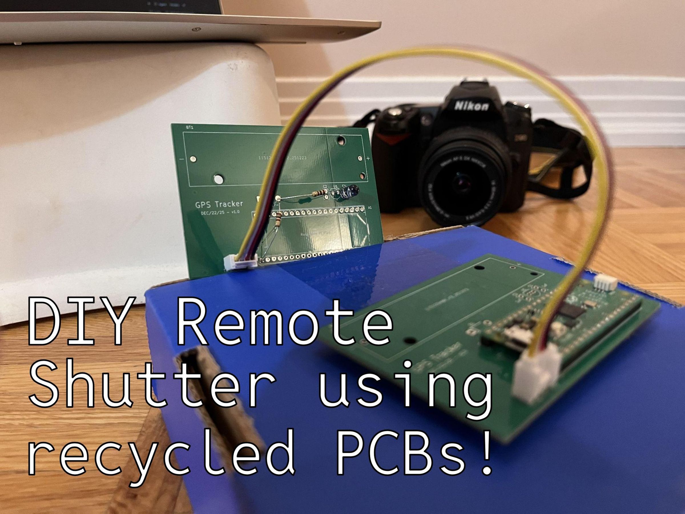
Hi everyone, my name is Daniel and I'm an engineering student. I have an upcoming camping trip, and wanted a remote shutter for astrophotography. This is what I came up with. It is designed to imitate the signal from the Nikon ML-L3 remote, and is compatible with the following cameras: D40 series, D50, D60, D70 series, D80, D90, D600, D610, D3000, D3200, D3300, D3400, D5000, D5100, D5200, D5300, D5500, D7000, D7100, D7200, D7500, D750, COOLPIX P900.
A problem I've always had is that I have leftover PCBs from my previous projects. Many PCB manufacturers only allow you to order a minimum of 5x boards, and this can be pretty wasteful especially when you only need one or two. In the spirit of being off the grid, I used two leftover PCBs from a GPS tracker project and did not order new PCBs for this project.
Of course, I don't expect you to have the same leftover PCBs, so I've designed a PCB specifically for this project. You can download the gerber files and submit them directly to the PCB manufacturer of your choice to get started. I hope, however, I've inspired you to try and hack something together with leftover PCBs.
References:
[1] https://www.nikonproductsupport.com/s/article/13803?language=en_US
Supplies
I was unable to upload either the zip file containing the gerbers or the individual gerber files to Instructables due to an unknown issue, so I've uploaded them into a Google Drive folder linked below. All you need to do download the gerber zip file and upload it to any PCB manufacturer.
https://drive.google.com/drive/folders/12jIRgTlAF1imqDHopTtEr385BC2W_Efc?usp=sharing
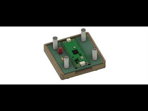
I also designed a PCB box that you can 3D print if you'd like, and the video above shows how it all fits together. It was modelled in Autodesk Fusion, and I used the Animation tab to create the video. It's super convenient for these proof of concept demonstrations, and it's pretty straightforward to learn. If you're a student, Autodesk offers free student access, which is pretty great.
If you'd like to follow along with this provided PCB, you'll need:
- 1x PCB
- 1x Raspberry Pi Pico
- 1x 940nm 1.2V IR (infrared) LED
- 1x 220Ω resistor
- 3D printer and filament (optional, for PCB box)
- 4x M6 bolts (optional, for PCB box)
- 4x M6 nuts (optional, for PCB box)
I used:
- 2x leftover PCBs from my GPS tracker project
- 1x Raspberry Pi Pico
- 1x 940nm 1.2V IR (infrared) LED
- 2x 100Ω resistor
- 2x 4 pin Seeed Studio Grove Female Header
- 1x 4 pin Seeed Studio Grove Cable
The Circuit
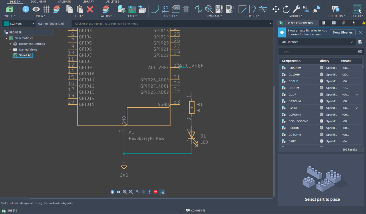 The circuit itself is pretty straightforward. We simply need to turn the LED on and off in a specific pattern to make the camera fire its shutter. To do this, we can connect the LED to one of the Raspberry Pi Pico's GPIO (general purpose input/output) pins.
We need just one more thing: a resistor to limit the current and make sure we don't exceed either of two things:
- Pi Pico GPIO max current rating (12 mA)
- LED max current rating (100 mA)
I used two resistors because I needed a way to bridge across the PCB (more on that in Step 2). The LED has a forward voltage drop of 1.2V, and I want to limit the current to 10mA, so we can simply use Ohm's law to approximate the resistor value needed.
VS = 3.3V
VLED = 1.2V
I = 10mA = 0.010A
R = (VS − VLED) / I
R = (3.3V − 1.2V) / 0.010A = 210Ω
The closest I could get to 210Ω was 2x 100Ω resistors. These will limit the current to 10.5 mA, which is still well within the max current rating of both the Pico GPIO and LED.
Repurposing Leftover PCBs
This is the most interesting step, where all the magic happens. Here are the schematic and PCBs from my GPS tracker project, with polygon pours indicated in white text:
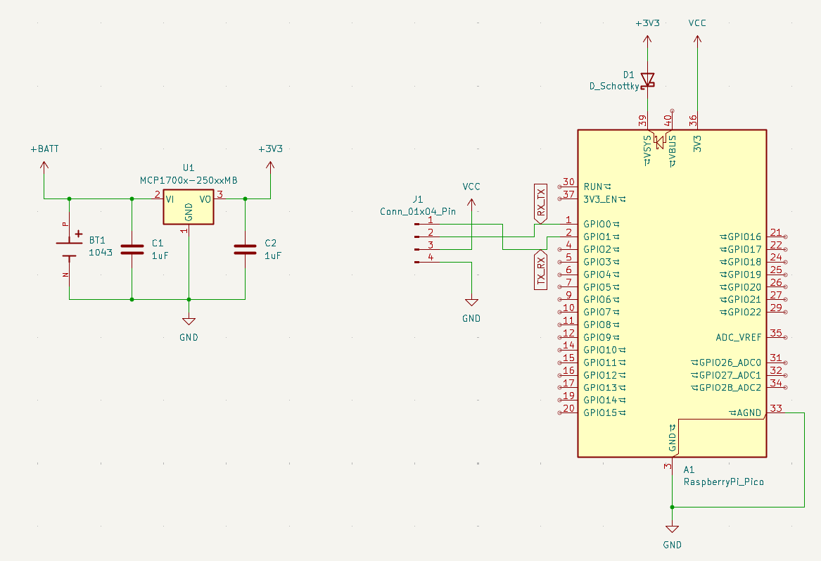
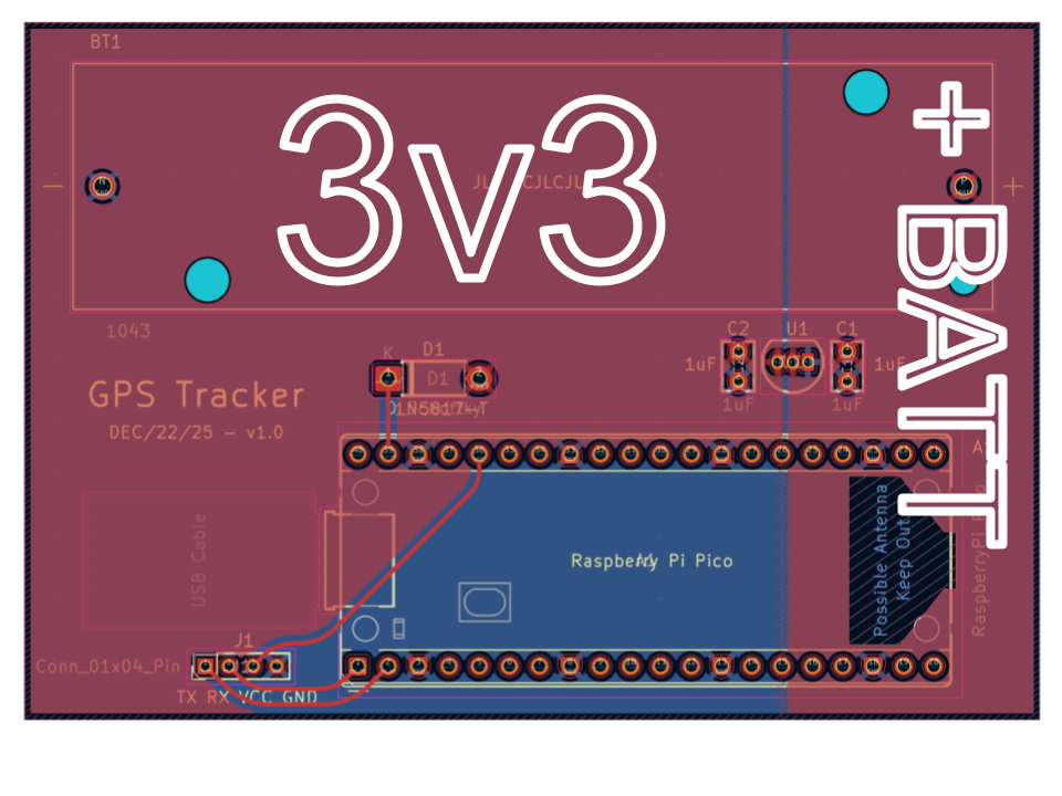
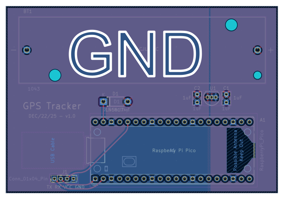
This GPS tracker board was designed to connect to a GPS sensor through the 4-pin connector, which has TX (transmit) and RX (receive) for data transfer, and VCC (3.3V) and GND for power transfer. I decided to use two of these boards: one for the Pi Pico and one for the IR LED and resistors. They are connected by a Seeed Studio Grove 4 pin cable that mates to the 4 pin connectors on each board. This way, the LED board is detachable from the Pico board.
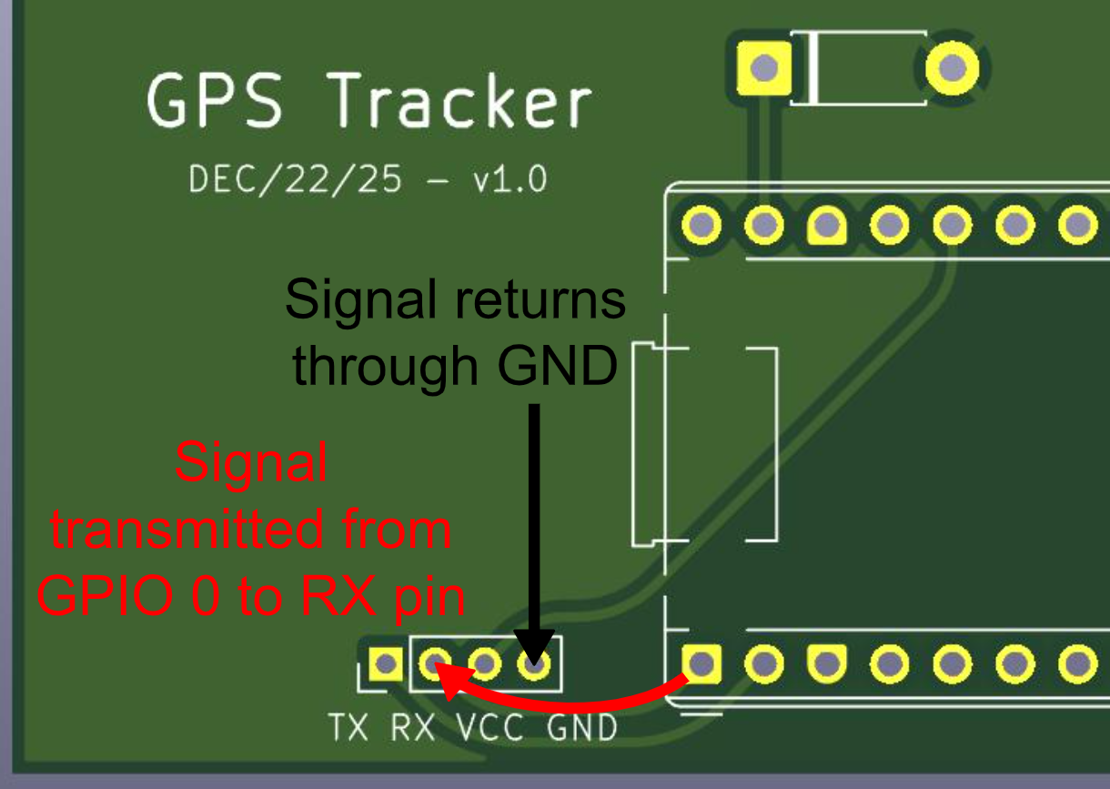
For Board #1, we can use RX (which is already connected to GPIO 0/physical pin 1) to drive the LED signal. The return path can then simply be through GND, which makes things really easy. So, the signal leaves Board #1 through the RX pin, then returns through the GND pin. Here's what that looks like:
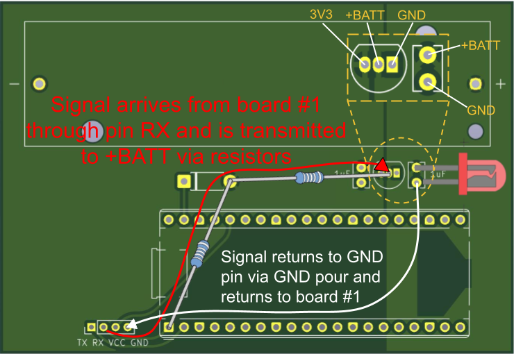
Next, we have to decide how to lay out the IR LED and resistors on Board #2. The signal arrives from board #1 through the RX pin, and we need it to return through the GND pin. There are two things here that make it much easier for us:
- The LED fits in the C1 footprint because it has a 2.54mm pitch (just like the capacitor C1)
- The C1 footprint bridges from the +BATT polygon pour to GND
In other words, if we place the LED in the C1 footprint and find a way to connect the RX pin to the +BATT polygon pour, we're done! To do this, I used two resistors. RX is already connected to GPIO 0/physical pin 1, so resistor #1 bridges from GPIO 0/physical pin 1 to the round diode pad (D1). Resistor #2 bridges from the round diode pad (D1) to the middle pad of component U1, which is connected to +BATT. Finally, the LED is placed in C1, with its longer leg (anode) connected to +BATT and its shorter leg (cathode) connected to GND. Here's what that looks like:
References:
[1] https://freesvg.org/plus-minus-of-led-2
[2] https://freesvg.org/resistor
Assembly
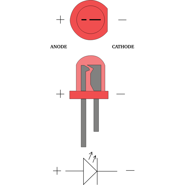
Time to solder everything up! The one thing to watch out for is the LED polarity - the longer led (anode) should be connected to the GPIO pin, while the shorter one (cathode) should be connected to GND. See below:
Here's what my completed boards looked like:
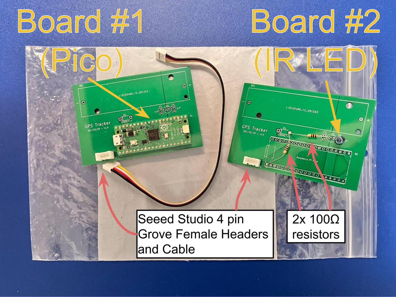
References:
[1] https://freesvg.org/plus-minus-of-led-2
The Signal
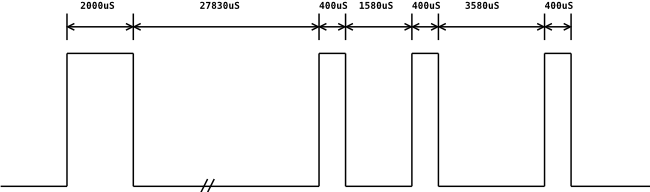
I found a website where somebody else has managed to deduce that the signal is a 38.4kHz PWM. This means that if we turn the signal on, the Pico blinks the LED on and off 38400 times a second. The timings are as follows:
- Signal on for 2000 microseconds
- Signal off for 27830 microseconds
- Signal on for 400 microseconds
- Signal off for 1580 microseconds
- Signal on for 400 microseconds
- Signal off for 3580 microseconds
- Signal on for 400 microseconds
- Signal off for 62300 microseconds
The signal is then repeated again.
The duty cycle is 50%, which means that the LED spends an equal amount of time on and off. For our Pico, when we want to turn the signal on, we alternate between writing GPIO 0 high (providing 3.3V) and low (0V).
References:
[1] https://www.bigmike.it/ircontrol/
Software
Time to code it up! I'll do my best to explain my thought process in snippets, but feel free to jump to Step 6 for the complete code.
Let's start with importing the libraries we need, and setting the exposure time and the GPIO pin. Please note that I used GPIO pin 0. If you are following along with the board I provided, you need to set your GPIO pin to 28.
To get the Pico to generate a PWM, we need to do four things:
- Get the slice number
- Get the channel number
- Set the frequency
- Set the duty cycle
On the Pico, a slice is a hardware block that allows us to generate a PWM signal. Each slice controls two channels. So, the first thing we need to do is find out what slice and channel our chosen GPIO pin corresponds to. Next is the frequency. The fPWM is 38.4 kHz, but the Pico's main clock runs at 125 MHz by default. To set the frequency and duty cycle, we need to set three things:
- Divider - the main clock is divided by this frequency to give us the frequency at which the slice counts. So for example if the Divider is set to 1.0, then the slice counts at 125 MHz / 1.0 = 125 MHz.
- Wrap - this setting controls the value that the clock counts to.
- Level - this setting controls the value at which we switch from high to low. So, for a 50% duty cycle, where the LED is on for the same amount of time it is off, this value should be half of Wrap.
To give you an analogy, let's say we have two runners in a relay race. Divider controls the speed of the runners, Wrap controls the length of the track, and Level controls when they hand off the baton. The relevant formulas are:
PWM frequency: fPWM = fCLK / [Divider × (Wrap + 1)]
Therefore, the required divider is: Divider = fCLK / [fPWM × (Divider + 1)]
As you can see, there are many different combinations of Divider and Wrap that satisfy our requirement for fPWM = 38.4 kHz. In general, however, choosing a smaller Divider value and a large Wrap value give you more flexibility when choosing a duty cycle. Compare Wrap = 2 and Wrap = 100, for example. For Wrap = 2, you can only set Level to 0, 1, or 2, corresponding to 0%, 50%, and 100% duty cycle. For Wrap = 100, you can set Level to a much greater variety of values. I ended up choosing the following values:
- Divider = 1.0
- Wrap = 3254
- Level = 1627
Note the command pwm_set_enabled(slice_num, false); which turns the pwm signal on and off.
Since we declared all the timing values in an array at the beginning, we can write a simple loop to turn the PWM signal on and off in the specific timing pattern we need.
Note that we're using busy_wait_us_32(timing[i]); instead of sleep_us(timing[i]); because it's more precise and we need the signals timed very precisely here.
Since the signal repeats once, we can simply call signal() twice.
Finally, here is an example main function that waits 500 ms in between images:
The Complete Code
Testing
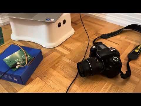
Here's a video demonstrating the project. The shutter speed in the video is 500 ms with a 1 s delay in between each image. Thanks for reading this Instructable and feel free to let me know if you have any questions.
Troubleshooting Tips:
- Check: is the LED wired correctly? (see Step 3)
- If you're not sure whether or not the LED is working, try filming it with the front (selfie) camera of your phone or your computer's webcam. On most newer phones, the rear camera blocks most infrared light. Also try using a TV remote - they use the same frequency and you should see a purplish white light.
- Use a multimeter to check the voltages across your resistor and LED. If the GPIO is outputting power correctly, the sum of those voltages should be the same as the voltage across the GPIO and GND.