Remote Wireless Igniter
by MosesJLJMGPhillips in Circuits > Arduino
46 Views, 1 Favorites, 0 Comments
Remote Wireless Igniter
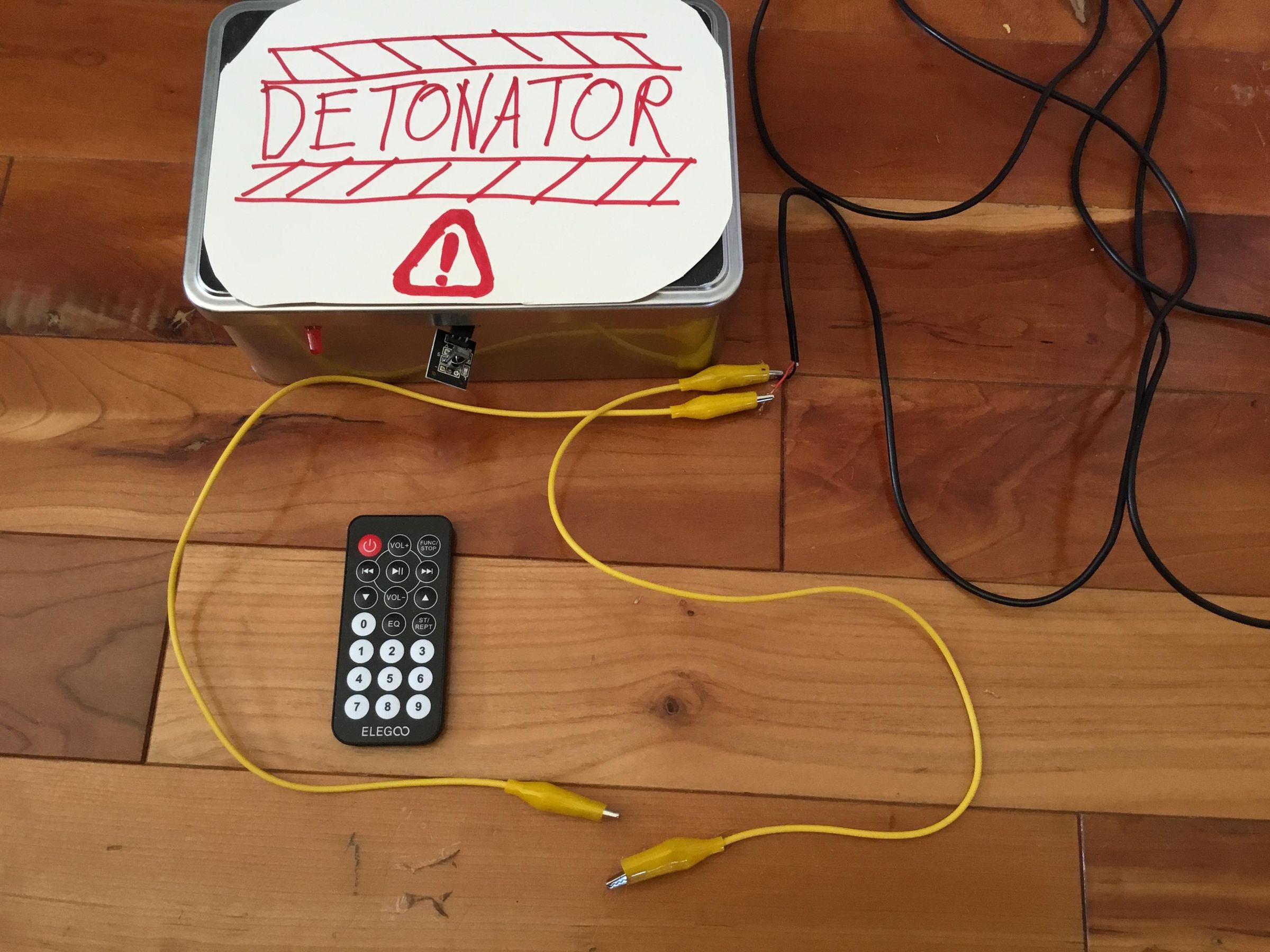
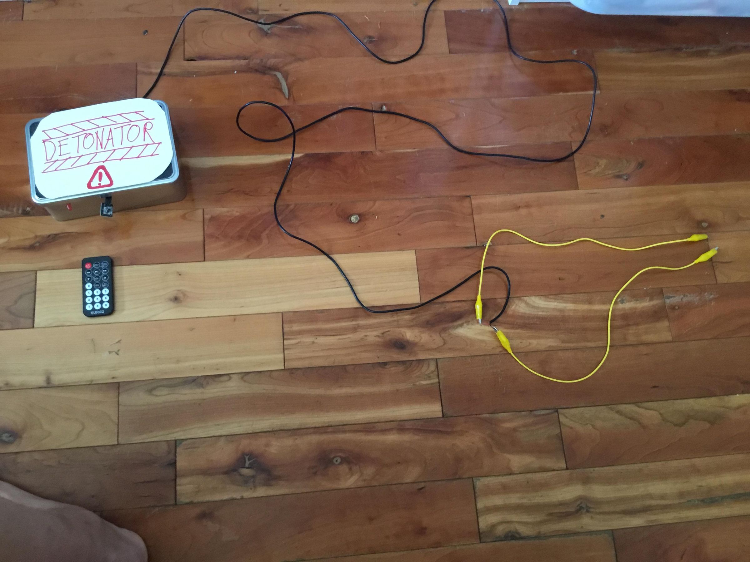
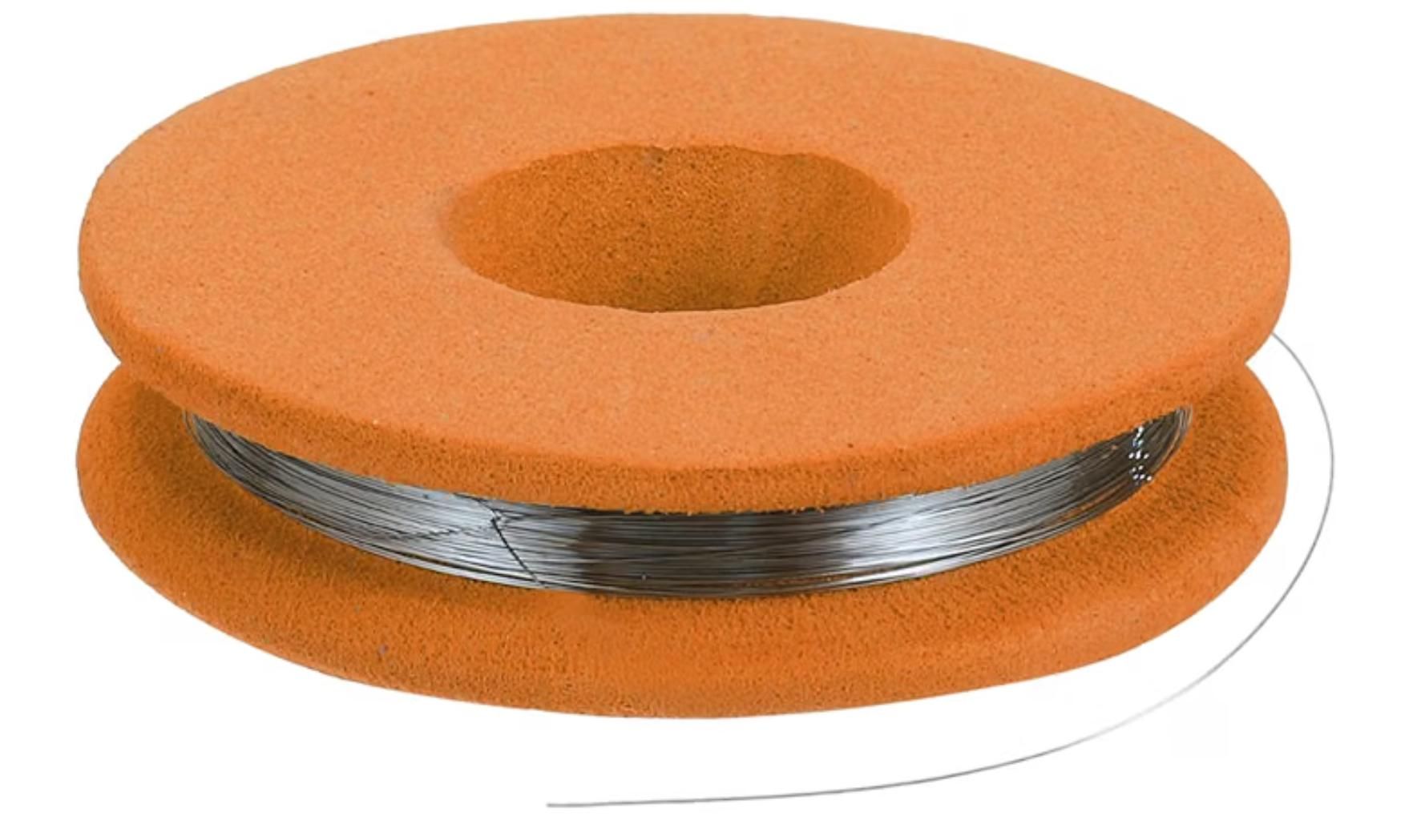
This is a wireless igniter that uses a remote control to trigger a relay which burns through some steel wool (or Nichrome wire would be just as good).
As the steel wool glows red hot and melts, it ignites an explosive such as gunpowder or something. Probably couldn’t ignite a fuse, but maybe if you used cotton wool.
This setup allows you to stand a safe distance away from a small explosion.
Also, it enables you to not just press a button, but put a code into the remote for extra security.
Supplies
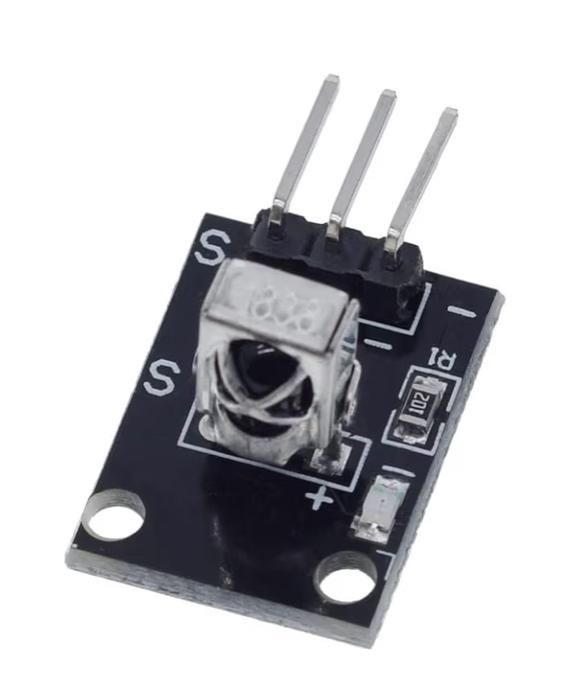
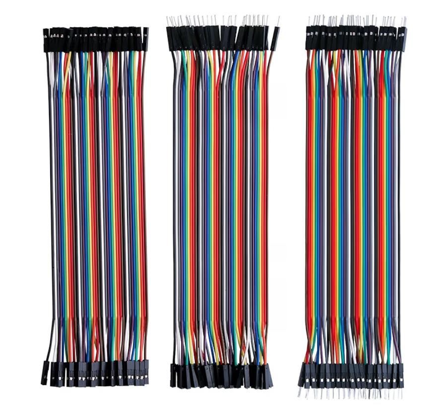
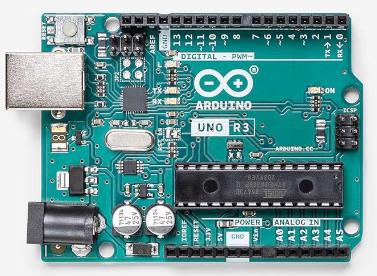
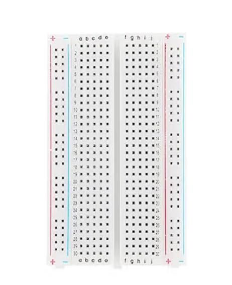



1 x Arduino Uno
3 x Male to Male Jumper wires
8 x Female to Male Jumper wires
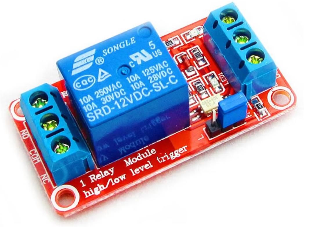
1 x Relay Module
1 x Two Core Wire (the longer, the safer your microcontroller!)
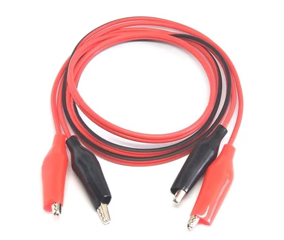
2 x Crocodile Clip Wires
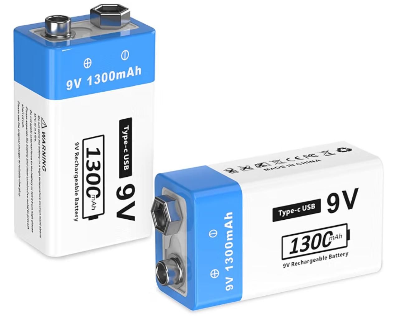
2 x 9V Batteries
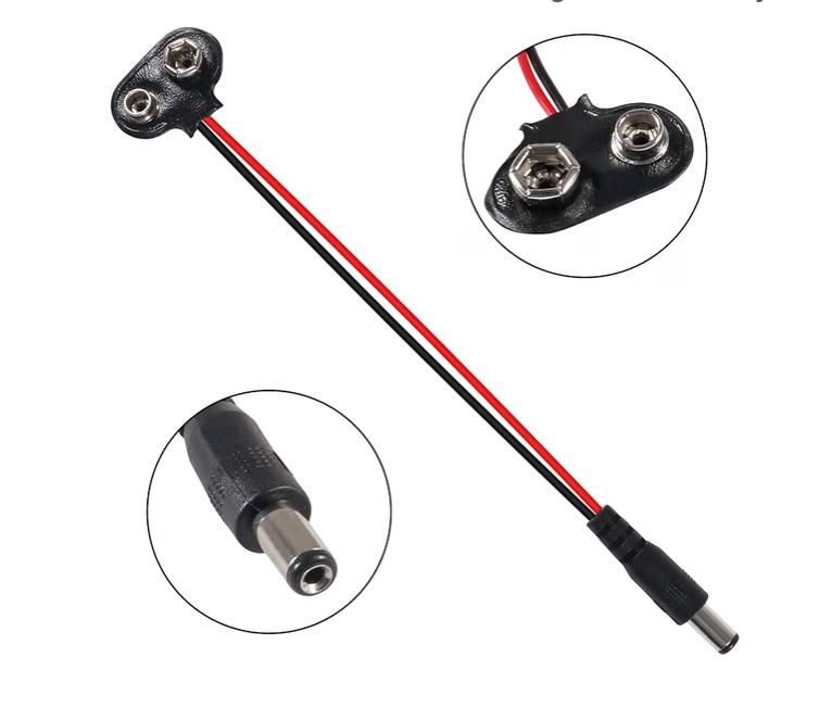
1 x 9V to Arduino connector wire
1 x 9V clip on connector wire
1 x IR Receiver
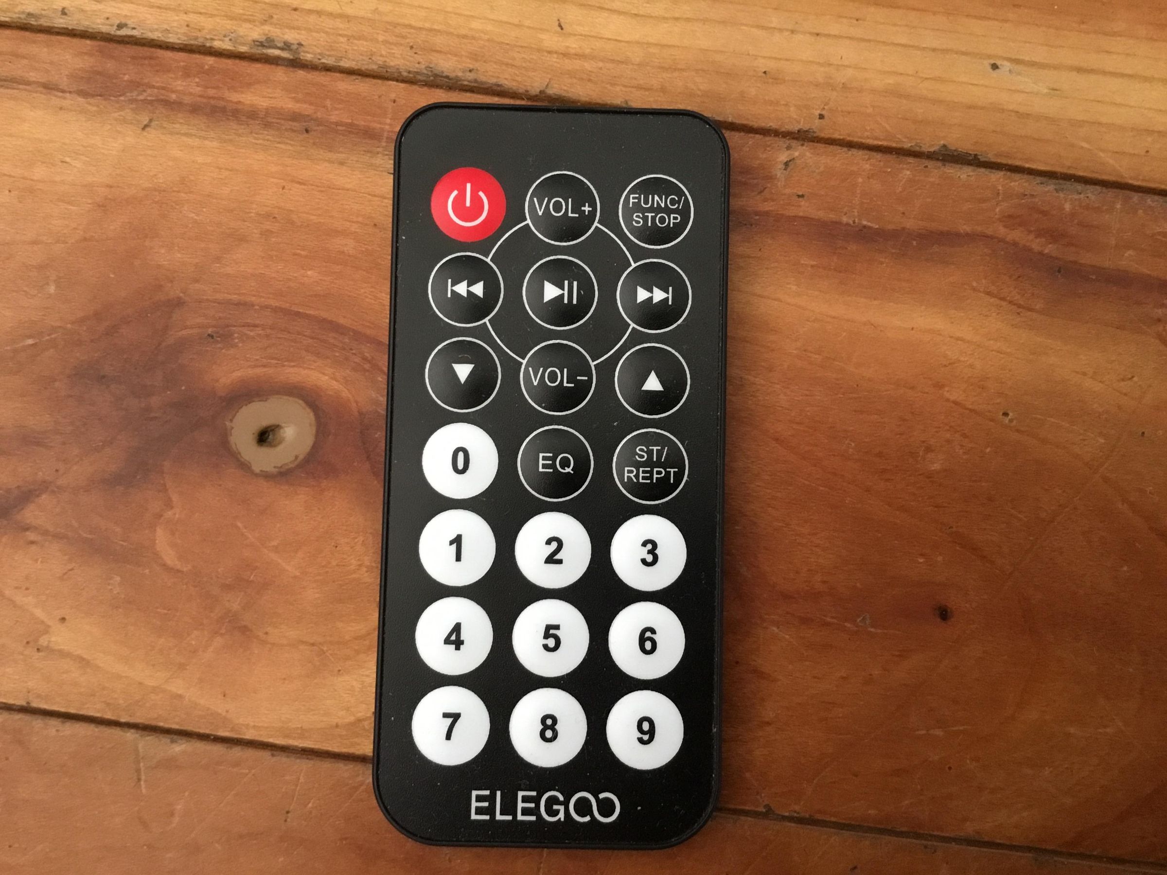
1 x IR Remote
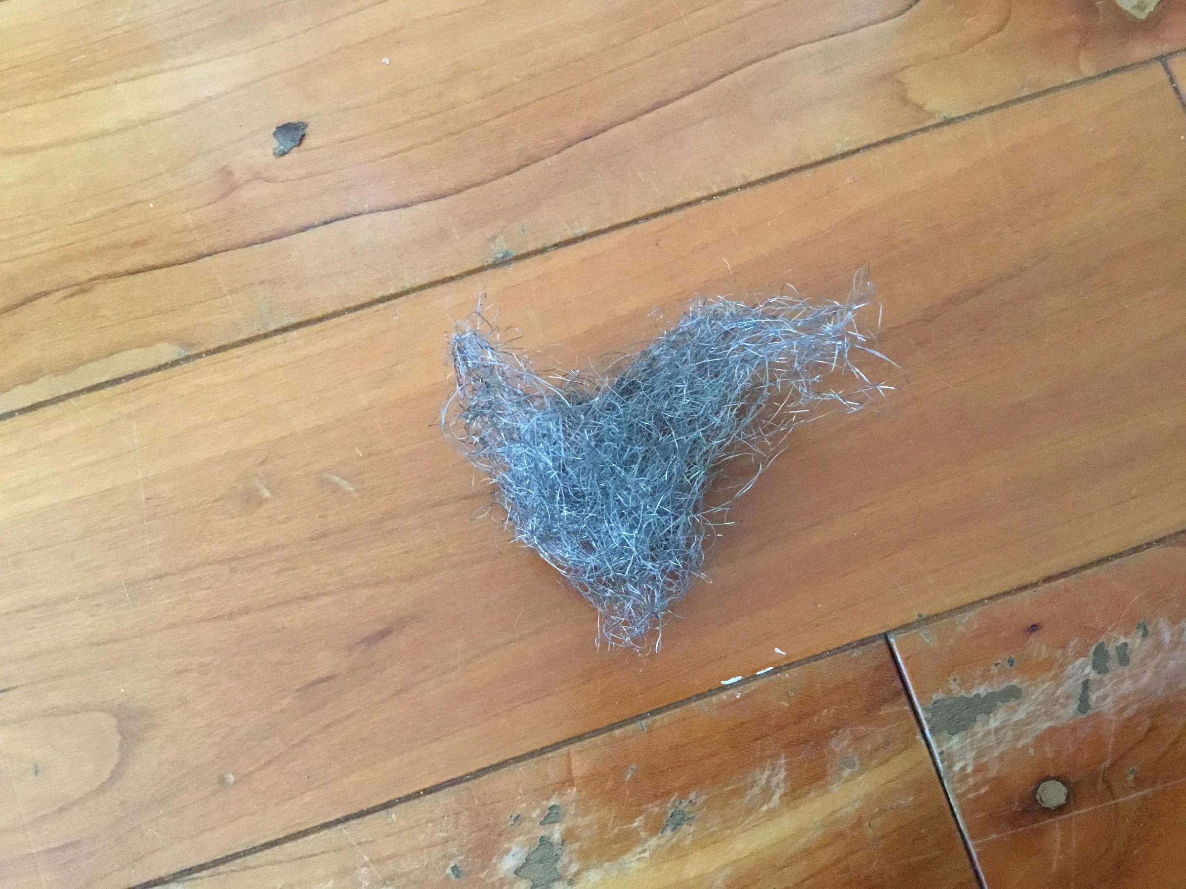
1 x Ball of Steel Wool
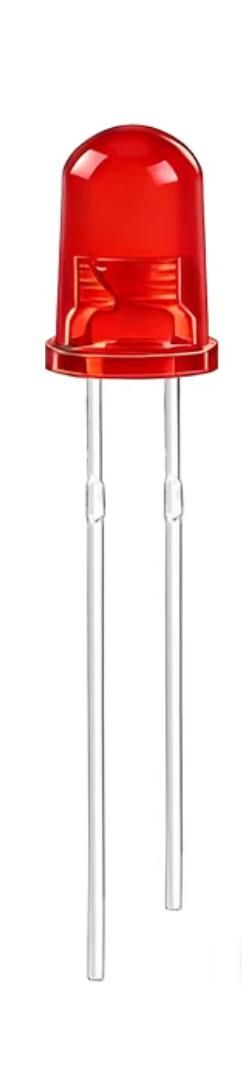
1 x Red LED (can of course be any other colour)
1 x Small Solderless Breadboard
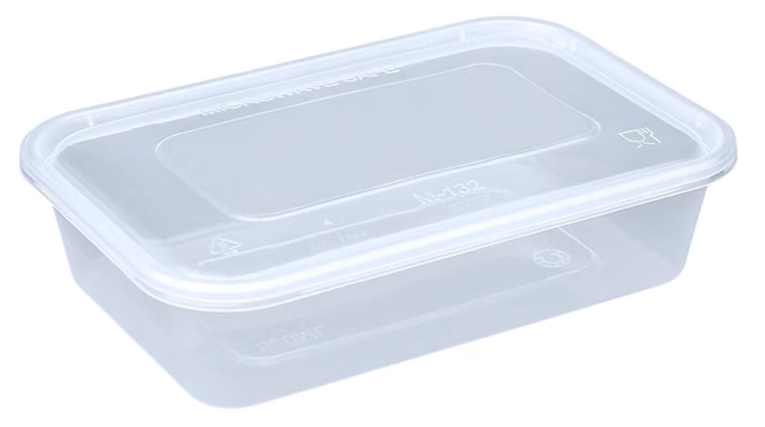
1 x Container (metal tin is best to protect electronics from explosion, with plastic tupperware inside to prevent short-circuit)
1 x 220 ohm Resistor
Connect Components to Arduino
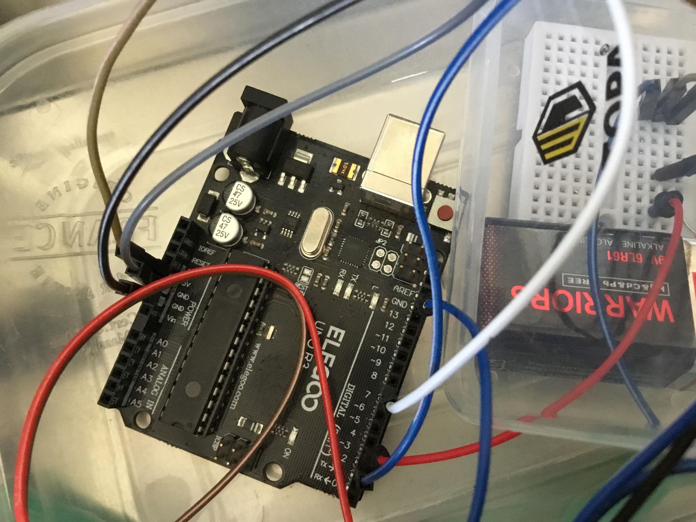
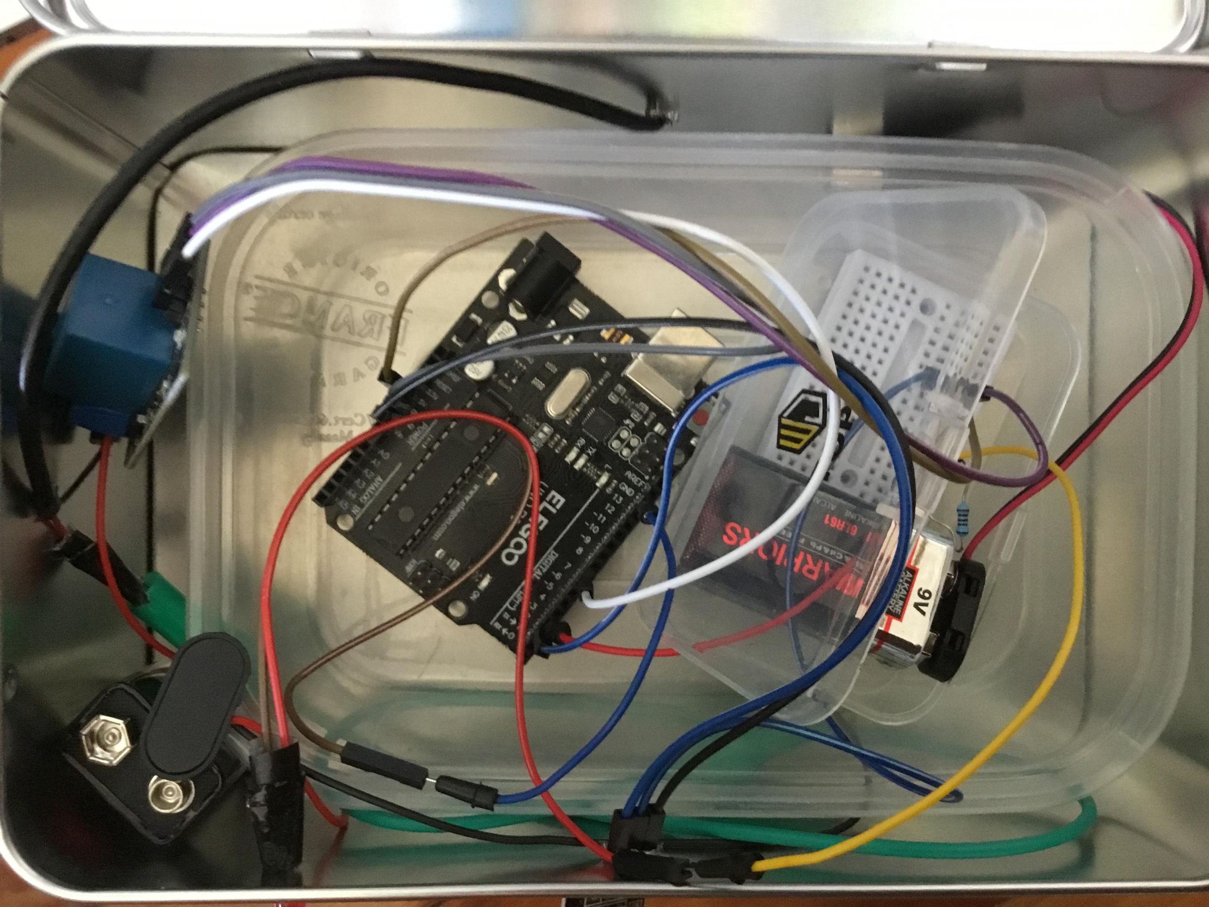
Arduino:
5V to + Rail on breadboard
IR Receiver:
GND to Arduino GND
VCC to + Rail on breadboard
SIG to Arduino Pin 2
Relay Module:
GND to Arduino GND
VCC to + Rail on breadboard
SIG to Arduino Pin 7
LED:
+ Leg to 220 ohm Resistor
- Leg to Arduino GND
Resistor:
Leg one to Arduino Pin 3
Leg two to Led + Leg
Attach Two Core Wire to Relay Output, and Two-core Wire to Crocodile Clip Wires
Attach one core wire of the two-core wire to the Positive (red) wire of the 9V snap-on connector. Connect the Negative (black) wire of the 9V snap-on connector to the Relay Module Positive Output, and the other core wire to Relay Module Negative Output. Then on the other side of the two-core wire attach one core wire to a crocodile clip wire, and the other core wire to the other crocodile clip wire.
Attach Steel Wool/Nichrome Wire
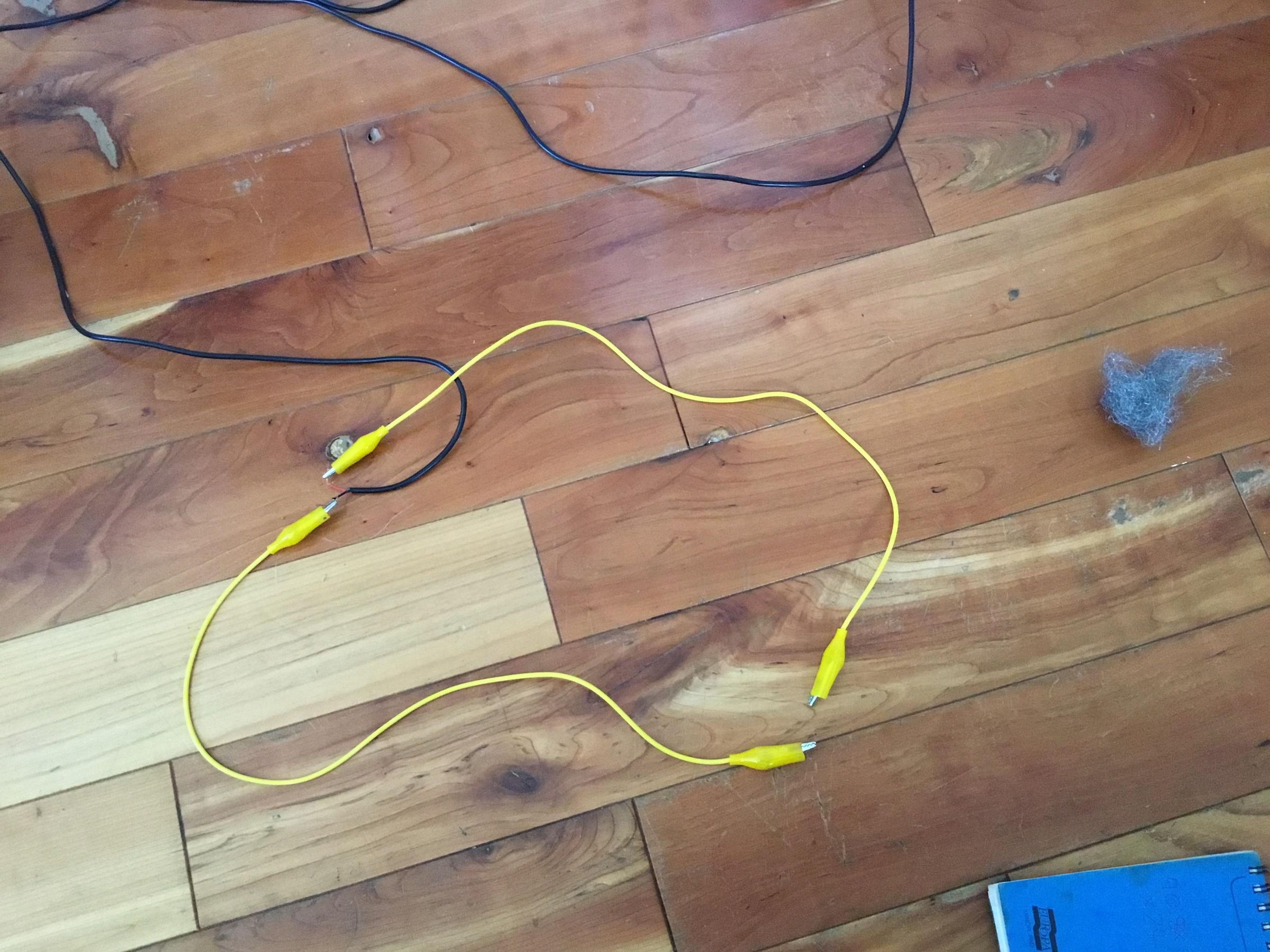
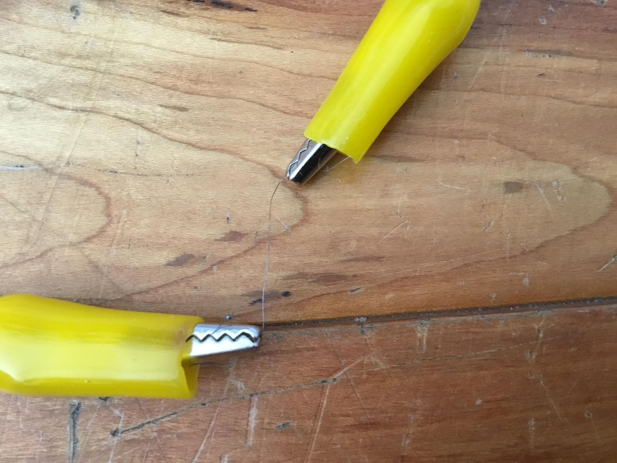
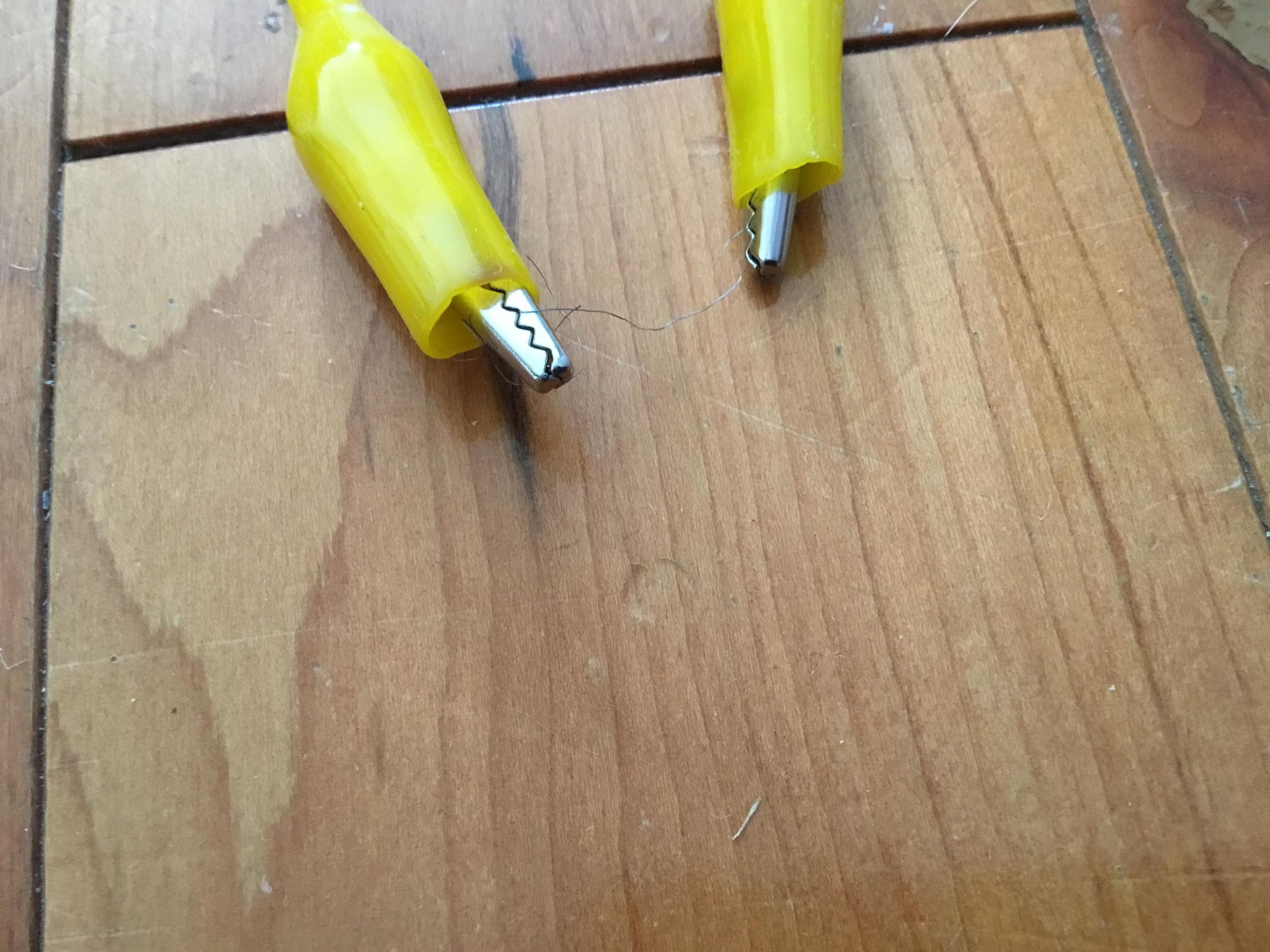
Cut a piece of steel wool or Nichrome wire about 2cm long, and attach one end to one crocodile clip wire, and the other end to the other crocodile clip wire.
If you use steel wool, (which melts), or if you are detonating an explosive, you will need to repeat this step every time.
Flash the Code
Now to flash the code to the Arduino. This code adds extra security, because
A) it only recognises the correct code from the remote
B) you have to put the code in within ten seconds
C) it uses a watchdog, so if the Arduino gets stuck in a dangerous position, it will reset automatically.
(This code is built for two relays in series for extra safety, but I didn’t end up putting both in.)
Copy and paste the following code into the Arduino IDE:
// Remote Igniter Code
// By Moses J.L.J.M.G. Phillips
#include <IRremote.h>
#include <avr/wdt.h> // Include the internal Watchdog Timer library
// --- Pin Definitions ---
const int IR_RECEIVE_PIN = 2;
const int RELAY_PIN_A = 7; // Primary control line
const int RELAY_PIN_B = 8; // Secondary control line (Logic link)
const int STATUS_LED = 3; // Wired to a separate LED on Pin 3
// --- Combo Configuration ---
// These are mapped to your specific remote's captured 32-bit hex values
const unsigned long CODE_1 = 0xE916FF00; // '1' button
const unsigned long CODE_2 = 0xF30CFF00; // '2' button
const unsigned long CODE_3 = 0xBA45FF00; // '3' button
const unsigned long CODE_4 = 0xE916FF00; // '4' button (shares the same hex footprint on your remote)
const unsigned long CODE_POWER = 0xA15EFF00; // 'Power' button
const int SEQUENCE_LENGTH = 5;
// The precise 5-digit key ordering: 1 -> 2 -> 3 -> 4 -> Power
const unsigned long SECRET_SEQUENCE[SEQUENCE_LENGTH] = {CODE_1, CODE_2, CODE_3, CODE_4, CODE_POWER};
// --- Timing Configuration ---
const unsigned long TIMEOUT_DURATION = 10000; // 10s code entry limit
const unsigned long WARNING_DURATION = 5000; // 5s arming warning period
// --- State Variables ---
int currentStep = 0;
unsigned long sequenceStartTime = 0;
bool isArmed = false;
unsigned long armStartTime = 0;
void flashErrorLED() {
digitalWrite(STATUS_LED, HIGH);
delay(150);
digitalWrite(STATUS_LED, LOW);
}
void setup() {
// PRECAUTION 4: Set pins LOW *before* enabling output to completely eliminate boot-glitches
digitalWrite(RELAY_PIN_A, LOW);
digitalWrite(RELAY_PIN_B, LOW);
digitalWrite(STATUS_LED, LOW);
pinMode(RELAY_PIN_A, OUTPUT);
pinMode(RELAY_PIN_B, OUTPUT);
pinMode(STATUS_LED, OUTPUT);
Serial.begin(9600);
IrReceiver.begin(IR_RECEIVE_PIN, DISABLE_LED_FEEDBACK);
Serial.println(F("System Booted. Enabling Watchdog..."));
// FIXED: Expanded the Watchdog window to 4 seconds to prevent the 1-second trigger delay from tripping it.
wdt_enable(WDTO_4S);
Serial.println(F("System Ready. Enter code (10s limit)..."));
}
void loop() {
// PRECAUTION 2: "Reset" the watchdog timer on every single loop iteration.
wdt_reset();
// Handle the Active Arming / Warning Cycle (Precaution 3)
if (isArmed) {
unsigned long elapsedArmTime = millis() - armStartTime;
// Create a rapid warning blink on the separate LED without using blocking delay()
if ((elapsedArmTime / 100) % 2 == 0) {
digitalWrite(STATUS_LED, HIGH);
} else {
digitalWrite(STATUS_LED, LOW);
}
// Check if any IR button is pressed during the warning phase to trigger an ABORT
if (IrReceiver.decode()) {
if (IrReceiver.decodedIRData.decodedRawData != 0x0) {
Serial.println(F("!!! ABORT SIGNAL DETECTED !!! Sequence canceled."));
isArmed = false;
digitalWrite(STATUS_LED, LOW);
flashErrorLED();
}
IrReceiver.resume();
}
// If the 5-second countdown finishes without an abort, execute trigger
if (isArmed && (elapsedArmTime >= WARNING_DURATION)) {
isArmed = false;
Serial.println(F("WARNING COMPLETE: Activating outputs..."));
// PRECAUTION 1: Dual-Pin activation sequence
digitalWrite(STATUS_LED, HIGH); // Solid status light
digitalWrite(RELAY_PIN_A, HIGH);
digitalWrite(RELAY_PIN_B, HIGH);
delay(1000);
digitalWrite(RELAY_PIN_A, LOW);
digitalWrite(RELAY_PIN_B, LOW);
digitalWrite(STATUS_LED, LOW);
Serial.println(F("Execution finished. System reset."));
}
return; // Skip normal code processing while armed
}
// Handle code entry expiration timeout
if (currentStep > 0 && (millis() - sequenceStartTime >= TIMEOUT_DURATION)) {
Serial.println(F("TIMEOUT: 10 seconds exceeded. Sequence reset."));
currentStep = 0;
flashErrorLED();
}
// Process standard IR code inputs
if (IrReceiver.decode()) {
unsigned long receivedCode = IrReceiver.decodedIRData.decodedRawData;
if (receivedCode != 0x0) {
Serial.print(F("Received: 0x"));
Serial.println(receivedCode, HEX);
if (currentStep == 0) {
sequenceStartTime = millis();
}
if (receivedCode == SECRET_SEQUENCE[currentStep]) {
currentStep++;
Serial.print(F("Correct! Progress: "));
Serial.print(currentStep);
Serial.print(F("/"));
Serial.println(SEQUENCE_LENGTH);
if (currentStep == SEQUENCE_LENGTH) {
Serial.println(F("CODE ACCEPTED: Entering 5-second Arming Countdown. Press ANY key to abort!"));
isArmed = true;
armStartTime = millis();
currentStep = 0;
}
}
else {
Serial.println(F("WRONG BUTTON: Sequence reset."));
currentStep = 0;
flashErrorLED();
// Fixed syntax checkpoint: Explicitly evaluates against index [0] of the array
if (receivedCode == SECRET_SEQUENCE[0]) {
currentStep = 1;
sequenceStartTime = millis();
Serial.println(F("Started new attempt with first button."));
}
}
}
IrReceiver.resume();
}
}
Housing the Electronics
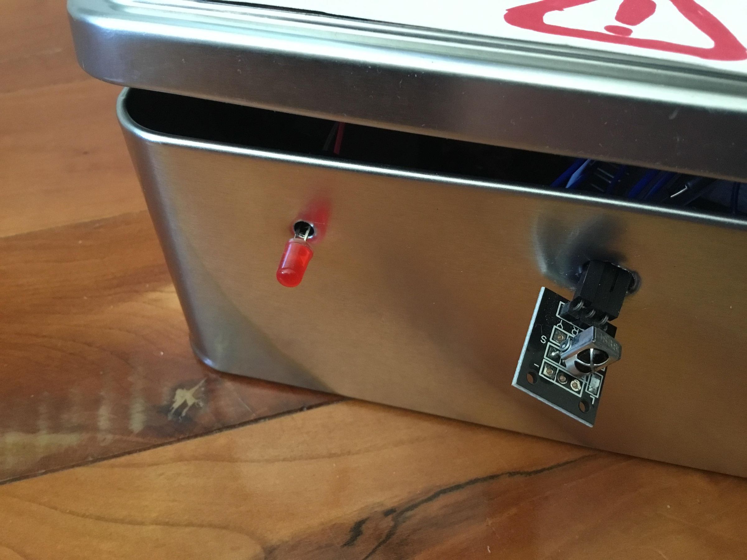
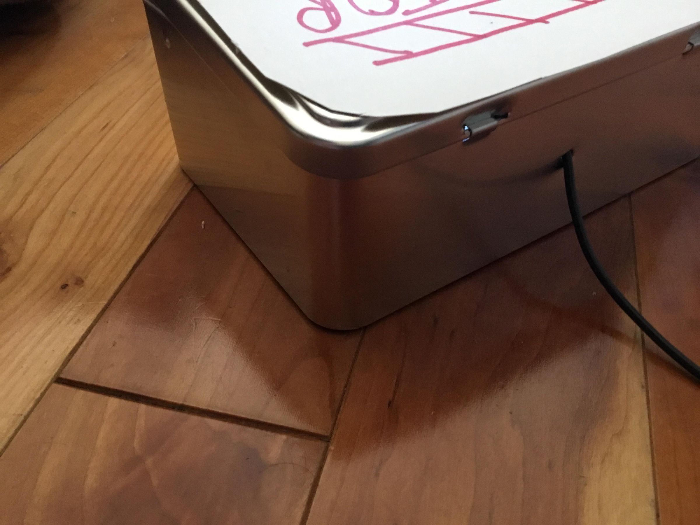
Cut two small holes in the front of your tin, and one in the back. Put the plastic tupperware in, then stuff the electronics into that.
Push the two core wire through the hole in the back (you will have to remove the crocodiles clip wires first), and the LED through one of the front holes, and the IR Receiver through the other front hole.
Testing.
Snap on the two 9V batteries. The Arduino’s green light will turn on. Close the tin’s lid.
Put in the code on the remote, with the remote facing the IR receiver. My code is 1234 then red Power button, but you can change that by changing the IR codes in the code.
If you put in the wrong code, the red LED will flash once. If you put in the right code, the red LED will flash on and off for five seconds, then the relay will click on and the steel wool will glow red hot and melt!
When using this to ignite something, stretch the two core wire to its full length to protect the Arduino, put the explosive touching the steel wool, or even better with the steel wool wrapped around the explosive, then stand at least 5m away from the Igniter box on the opposite side to the explosive. Then put in the code, stay far back, and wait for the explosion.
If it doesn’t go off after ten seconds, put in the code again. If it still doesn’t work after a further minute, cautiously go forward and check that everything is working. Use something to shield you, in case the explosive goes off unexpectedly.