Repair a Sea-Doo ECU
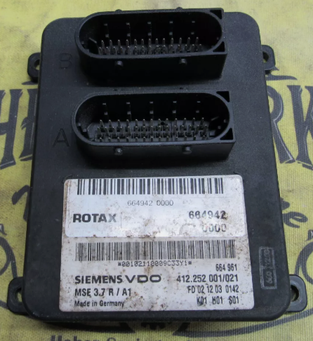
What makes these ECUs tricky to fix is the silicone potting compound. Removing it is a nasty, time-consuming job. However, a secondhand ECU can cost upwards of $800 USD, so perhaps the suffering is justified. These instructions pertain to both the older 185HP (Siemens MSE 3.7 R) and newer 215HP (Siemens MSE 3.7 R/XX) class of ECUs.
Supplies
Chlorinated solvent (non-flammable brake fluid) look for 1,2-dichloroethylene
Separate the Two Halves of the ECU
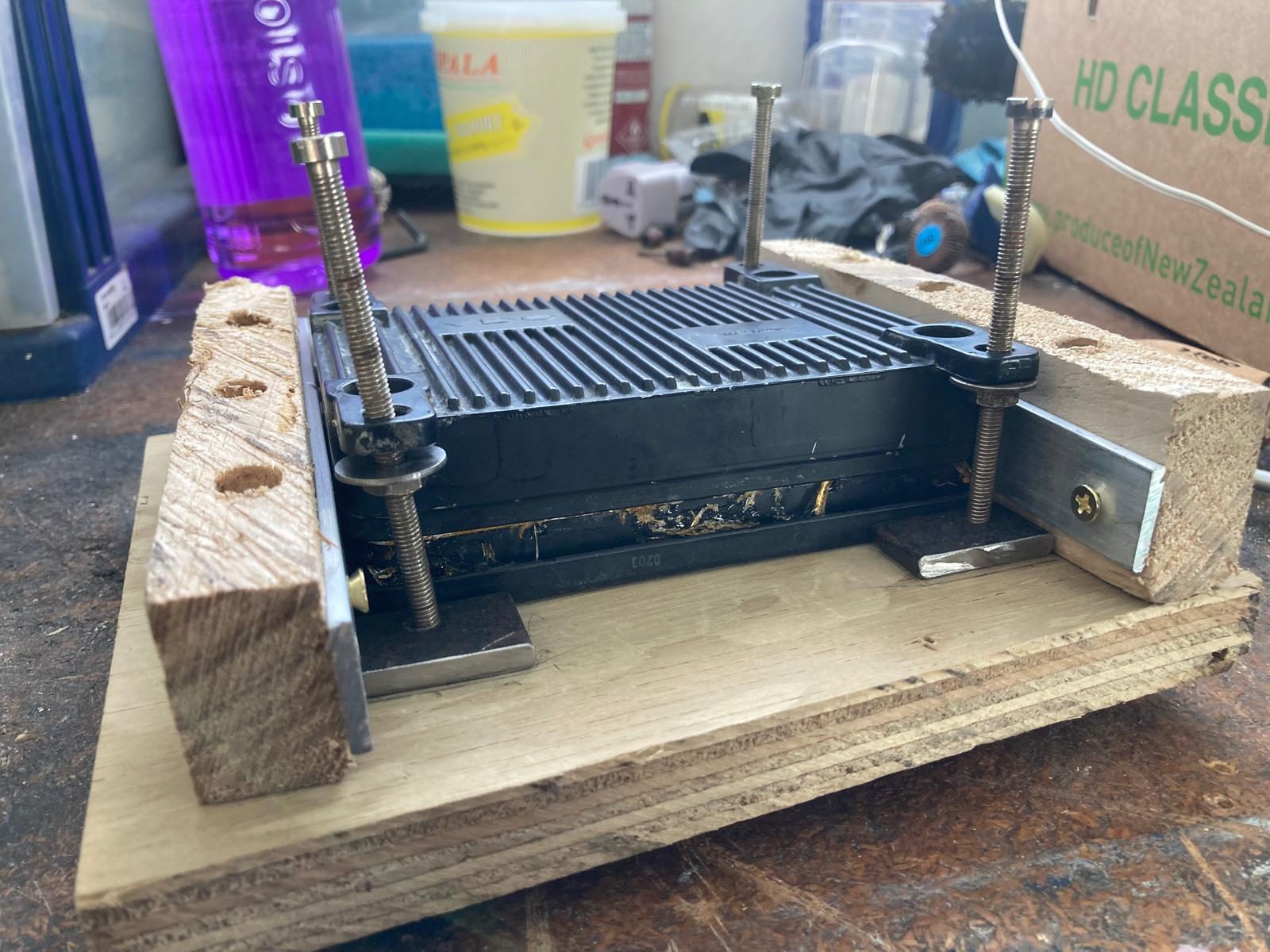

Build a jig to pry apart the two halves of the ECU. As you can see in the photo, I used two metal rails to pin down the plastic side of the ECU, while the die-cast aluminium side of the ECU is pried upwards with four nuts and bolts.
The following paragraph may, or may not be necessary, but this simply what I did. Weaken the silicone potting compound at the edges of the ECU with chlorinated solvent. Chlorinated solvents make the rubbery silicone become flaky and brittle. Any chlorinated solvent will work, but the easiest one to get hold of is 1,2-dichloroethylene (aka perchloroethylene, PCE, perc) found in non-flammable brake cleaner. Spray the fluid in the gap between the two halves of the ECU and wrap it up like a burrito with aluminium foil, and leave it for several hours. Avoid breathing the solvent because it's carcinogenic. Heat up the ECU prior to separating it. Warm it to about 50 degrees Celsius in the sun, and also use a heat gun but only on the aluminium side.
When you start tightening the screws, the plastic side of the ECU bends in the middle. Gently pry that middle part by twisting a large blade screwdriver in the gap, but be careful not to let it slip inside and damage internal components. Alternate between tightening of the four prying bolts on the jig, and the prying of the screwdriver. You may hear the silicone slowly tearing inside. Eventually the whole thing pops apart. Two aluminium filter capacitors embedded in silicone will often get ripped in half, but that's fine because that doesn't damage the PCB, and those caps should be replaced anyway.
Remove the Potting Silicone
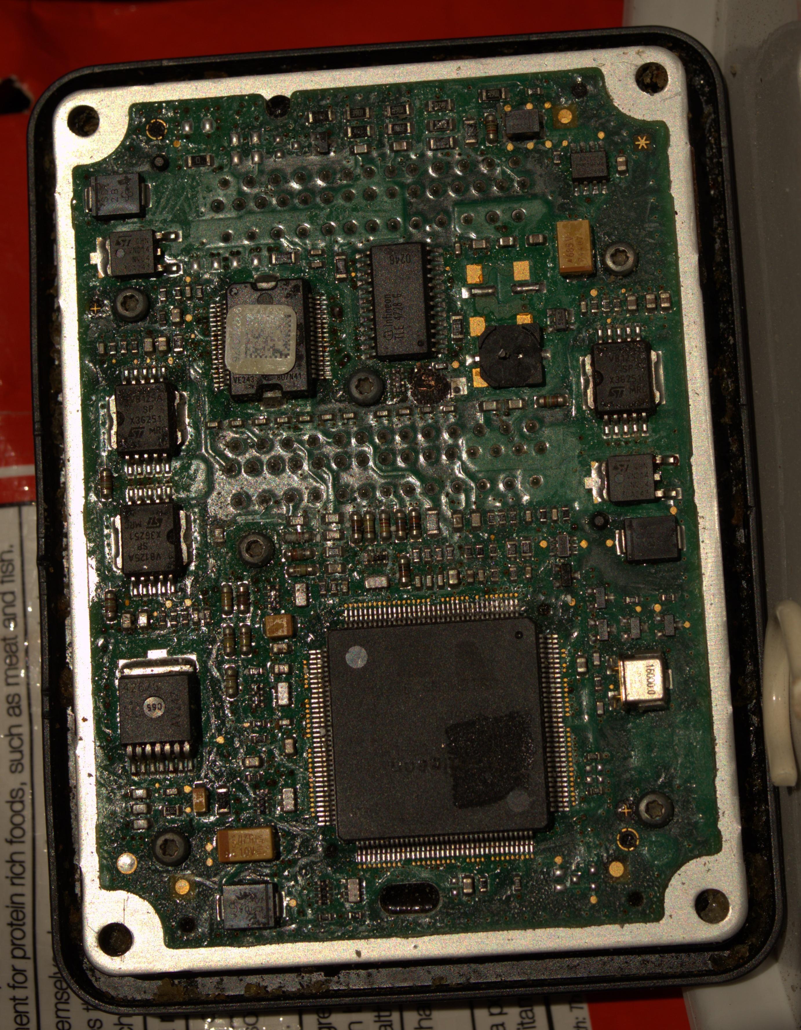
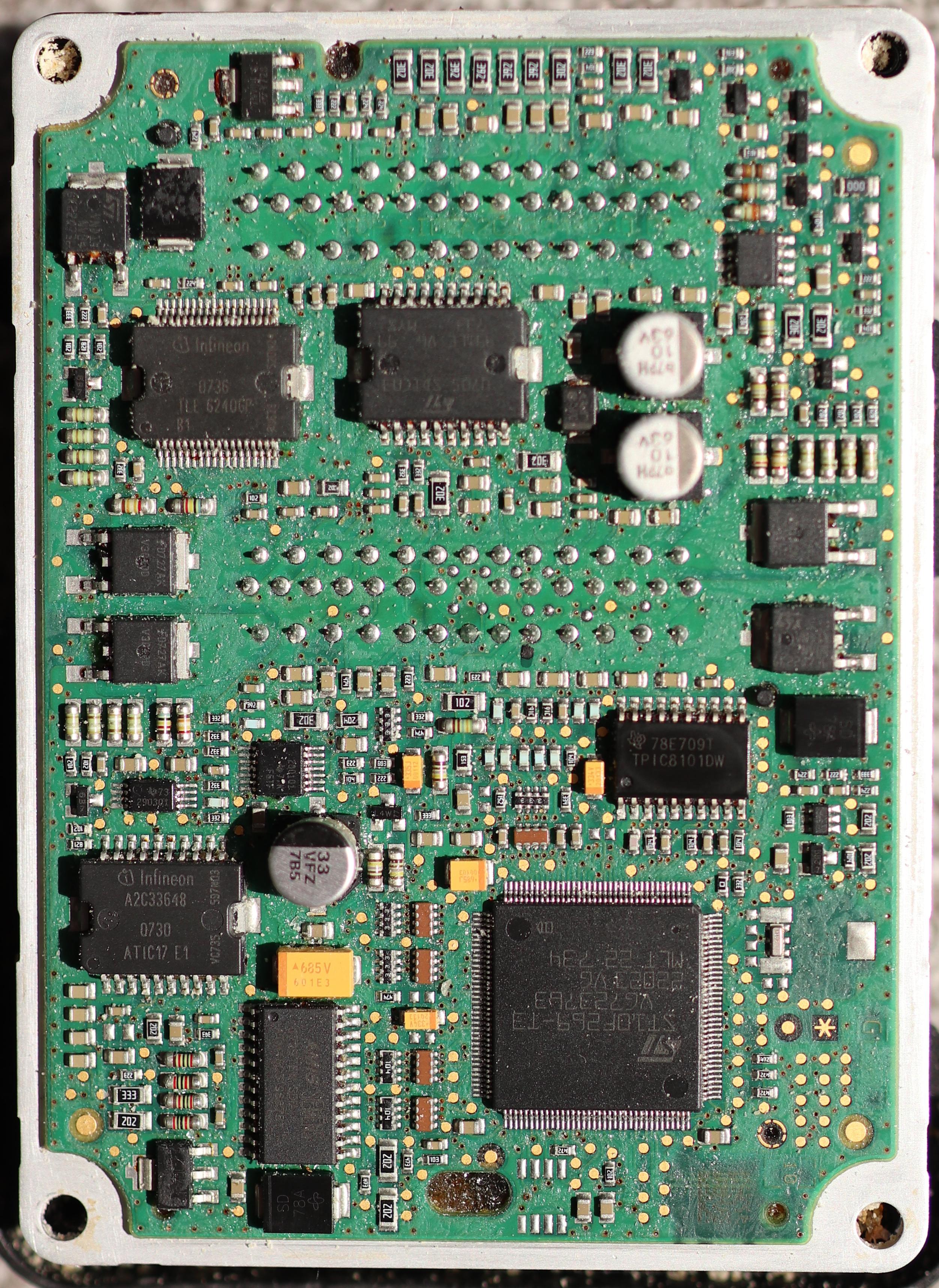
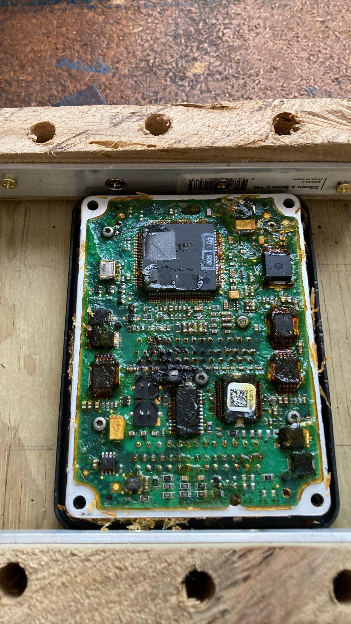
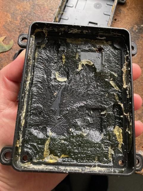
Expose the silicone to chlorinated solvent for a few hours. The flaky surface layer of silicone can then be brushed off with a nail brush or a tooth brush. Make a plastic scraper out of thin coke bottle plastic to gently dig out the large chunks of silicone. Be careful not to damage the fragile surface mounted components. This is a fiddly repetitive, and tedious process. The photos above show both the older 185 (left) and newer 215 (right) style of ECUs cleaned up nicely.
Fix the Board
A common fault is a blown TVS diode (as shown above). That's an easy fix, so long as it hasn't also damaged the multilayer PCB board as it did in my case.
If you don't have any clues, then begin by testing the resistance between the 12V rails. The 185 style should have a resistance of ~33 kΩ while the 215 style ECU should have a resistance of ~10.6 kΩ. I had a 185 that was measuring way too low, and the problem traced back to a damaged ignition coil driver.
Another approach to diagnose problems is to measure all the resistances at the PCB test points, and also on all the ICs. I've made some detailed notes on the correct resistances. You'll need the GIMP program to open the high-res pics. In those files you'll also find all the datasheets for all the ICs and other components on the boards. If you can improve the notes, then message me so I can incorporate your improvements.
Replacing the power ICs is no easy task because of the heat sinking on the back of the PCB. At a bare minimum you'll need Kapton tape, flux, a soldering iron, and a hot air reworking station.
Just for Fun, Flashing the ECU
A number of later model jet ski ECUs have identical hardware and are just loaded with different firmware. You can buy fancy expensive software to flash the firmware without opening the ECU, but if you've already opened the ECU then you can actually use free tools to flash it.
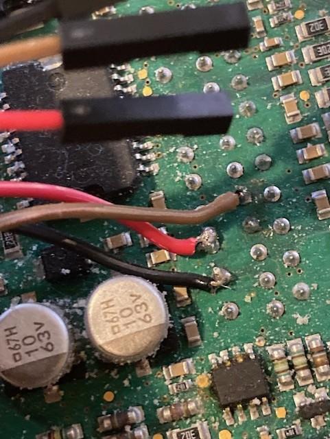
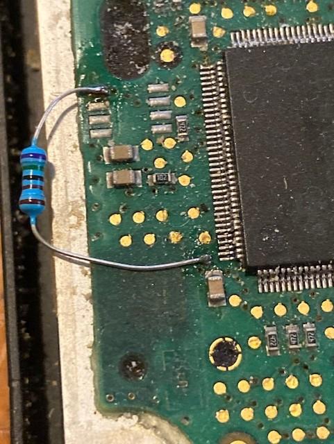
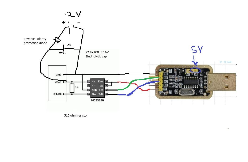
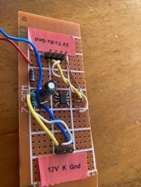
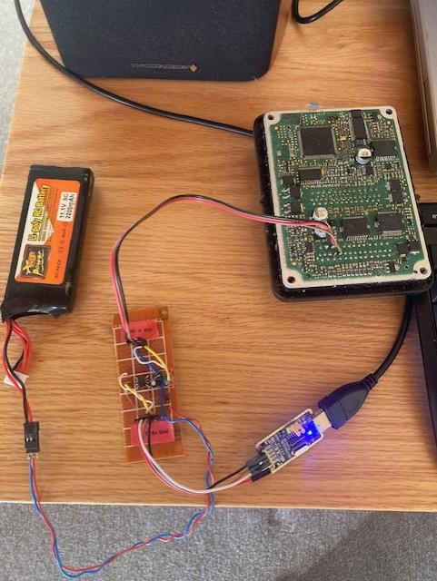
Pull the bootloader pin (pin #104) on the microcontroller to ground using a 4.7k to 10k resistor. There's a test pad connected to pin 104 which you can temporarily solder to the nearest ground source (see pic). K-line is a one-wire (half-duplex) protocol where logical FALSE corresponds to 12V and logical TRUE corresponds to 0V. Transmission is initiated with a "handshake" between the computer and ECU and the baud rate of 38400 is critical. I used a CH340G USB to serial converter, and I made a serial to K-line converter out of a MCZ33290 chip. Both components only cost a few dollars on ebay.
Use an external battery to power the ECU while flashing it. The reason for not using a mains powered 12V supply is because of the risk of a return path to your computer via mains. If that happens, then you'll likely destroy your motherboard and/or ECU.
Using ST10 Flasher V2.02 With Windows 10
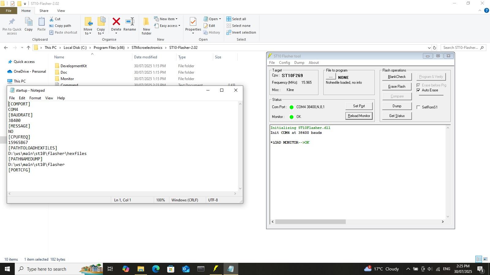
This procedure does not work in Windows 11, but it does work in Windows 10. Install the ST10 flasher V2.02 (it's in with my notes in the above link). Locate the executable (C:\Program Files (x86)\STMicroelectronics\ST10-Flasher-2.02). Right click to properties, then to compatibility, and then click "Windows 95". In the same directory, edit the startup.ini using notepad++. Figure out what COM port your CH340G USB adapter is using by opening the device manager in windows and plugging it in. Make sure it's using COM1 to 4 and then edit the startup.ini file accordingly. Connect everything together ie. the ECU to K-line converter, and the K-line converter to the Serial to USB converter (Tx->Tx and Rx->Rx). Make sure the serial converter is set to 5.0V, and not 3.3V. The startup sequence now has to be done exactly as follows:
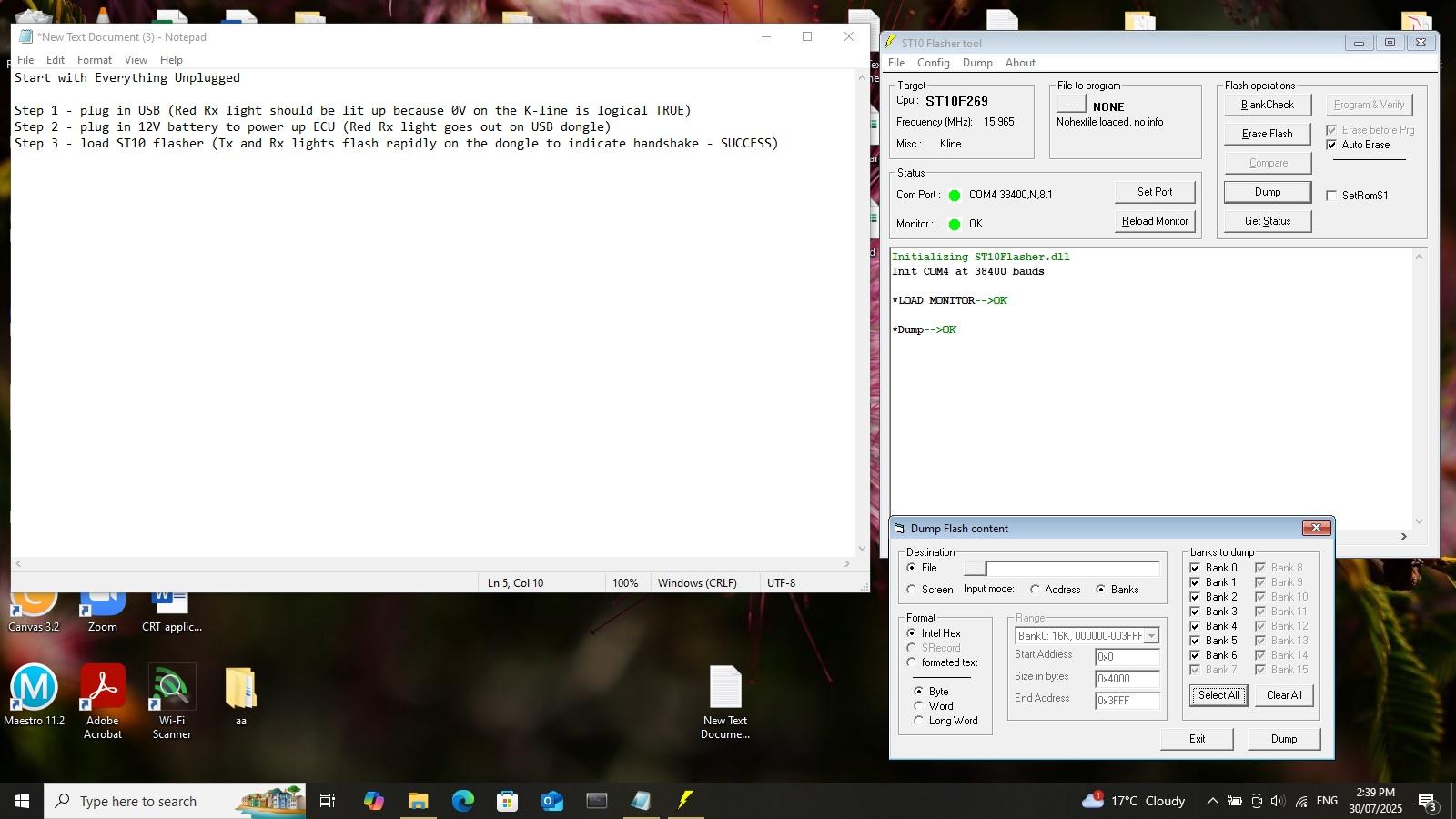
- Connect USB dongle to the computer. (The Rx light should illuminate on the dongle because the K-line is at 0V which is logical TRUE for K-line.)
- Connect the battery to power up the ECU. (The Rx light goes out because the K-line is now at 12V which is logical FALSE)
- Open ST10 flasher. (Both Tx and Rx lights will flash rapidly during the handshake - see the screenshot showing what successful communication looks like)
You can now upload and download the firmware from the microcontroller.