Replacing the LiPo Battery in a Motorola MDC300GW Dashcam
by seldomhobbyist1973 in Workshop > Cars
4 Views, 0 Favorites, 0 Comments
Replacing the LiPo Battery in a Motorola MDC300GW Dashcam
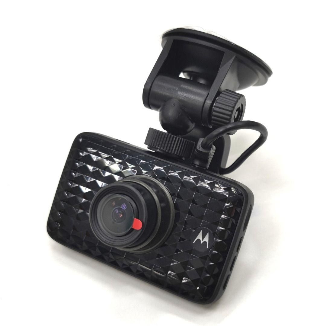
My Motorola MDC300GW dash cam stopped working because the battery failed and the battery protection circuit was interfering with it switching on properly when the car was running. There wasn't anything on the internet (that I could find) that explained how to open it correctly to replace the battery. I figured that if it didn't work anyway, I may as well have a go at opening and fixing it.
I damaged mine while opening it so that you don't have to. I assumed that the casing would come apart with with the typical edge clips because there were no visble screws. I was very wrong. I managed to break off the little stubs that the front casing screws are screwed into, but thankfully a bit of superglue saved the day.
During manufacture, the front cover with the camera and the PCB are screwed into the casing from the inside, and then the LCD is installed and the screen cover fitted with double-sided tape to create a screwless and (seemingly) unserviceable appearance.
I hope this project helps reduce the number of these units that are going into electronic waste because the battery has failed. It's quite a good little camera for the $18 that I paid for it 3 years ago.
Supplies
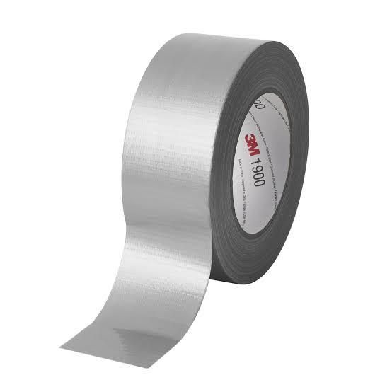
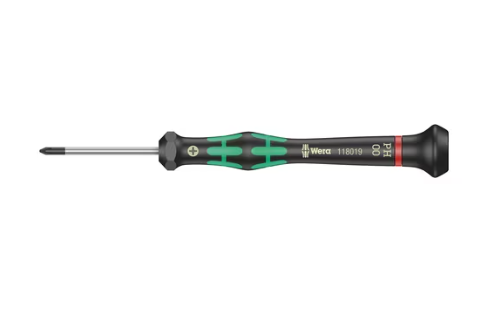
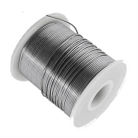
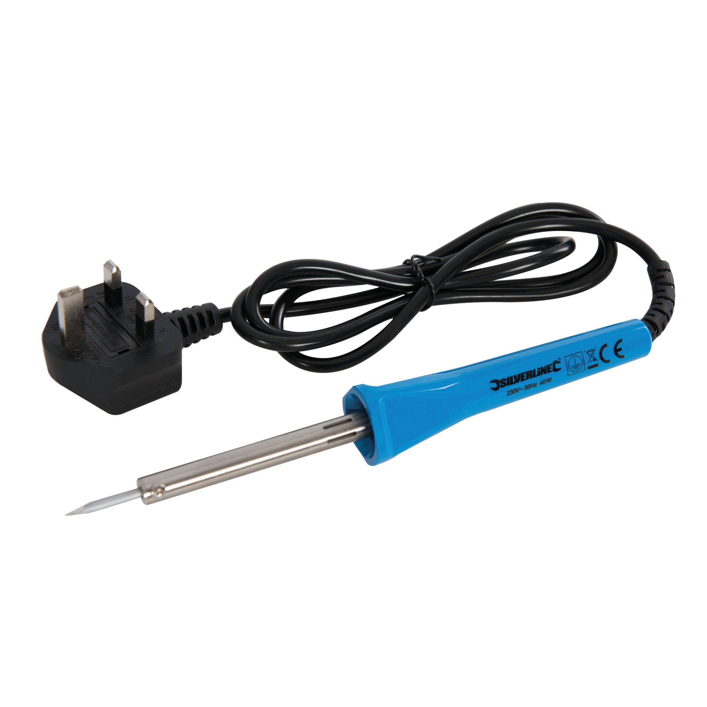
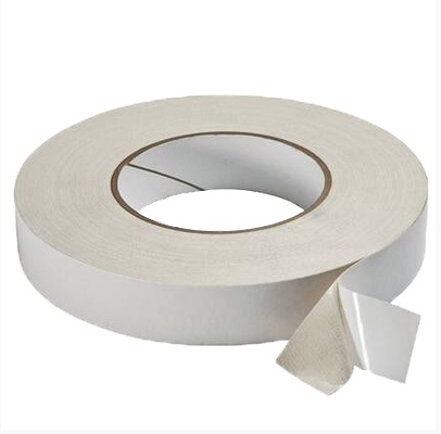
Duct tape
Soldering iron
Solder
Thin double-sided mounting tape
Small Phillips screwdriver
Isopropyl Alcohol
Prep
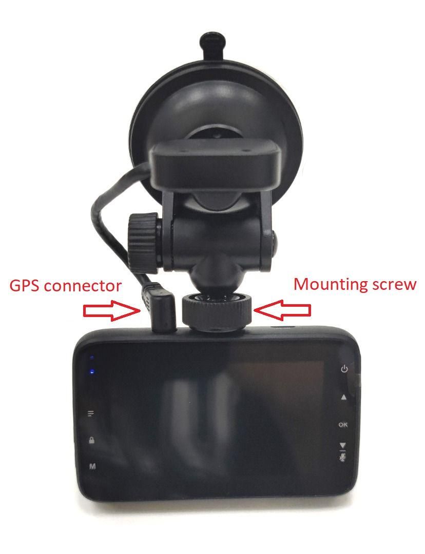
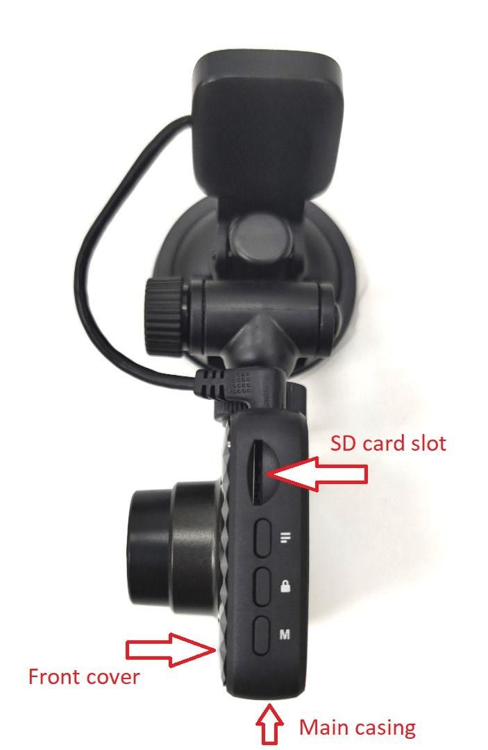
- Remove the camera from its winscreen mounting assembly.
- Remove the GPS and charge cables.
- Remove the SD card.
Remove the LCD Cover
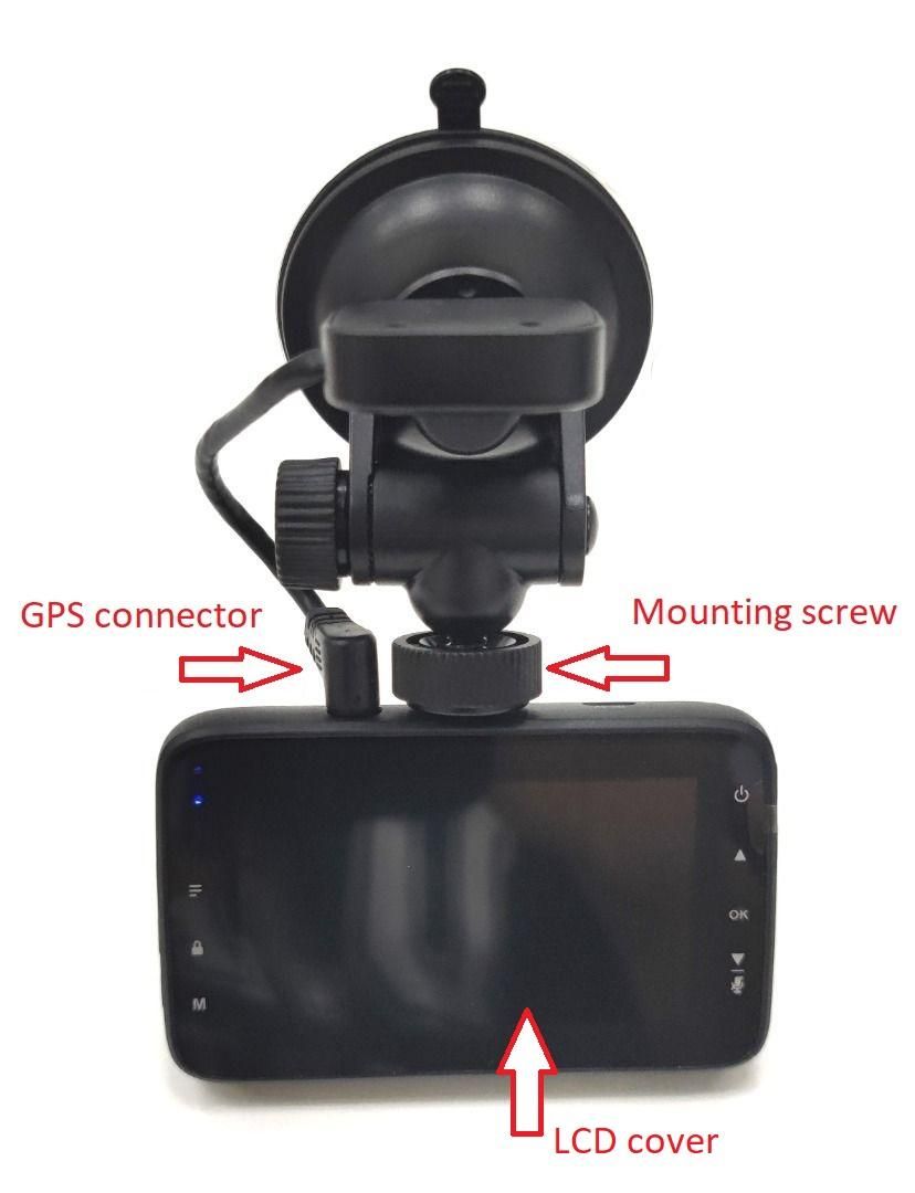
Apply some strong adhesive tape to the LCD screen cover, folding it near the edge to create a pulling tab. Duct tape is suitable for this purpose.
Pull on the tape to peel the screen cover away from the casing; it is held on with a small amount of double-sided tape. Avoid prying the screen cover with tools to prevent damage to the LCD under the screen cover.
A strong suction cup may also work to peel away the screen cover.
When the LCD screen cover is off, the LCD screen in its metal enclosure will be exposed.
Remove the LCD Screen
Pry the LCD screen out of the casing, using the gaps between the LCD screen and the casing. It is not held with any screws. The LCD scrren has a ribbon cable attaching it to the PCB behind it, so take care not to damage it when prying it out.
Expose the PCB
Once the LCD screen is out, the 3 short screws holding the PCB to the main casing and the 3 long screws holding the front cover to the main casing are visible. These can be removed, allowing the front cover to be taken off the main casing. There are clips holding the front cover to the main casing opposite the front cover screws, but they release easily without damage. Be careful of the ribbon cable connecting the camera module in the front cover to the PCB. Be careful of the speaker and microphone, which are lightly glued into slots in the casing. It may not be necessary to remove these, although I did.
Remove the Old Battery
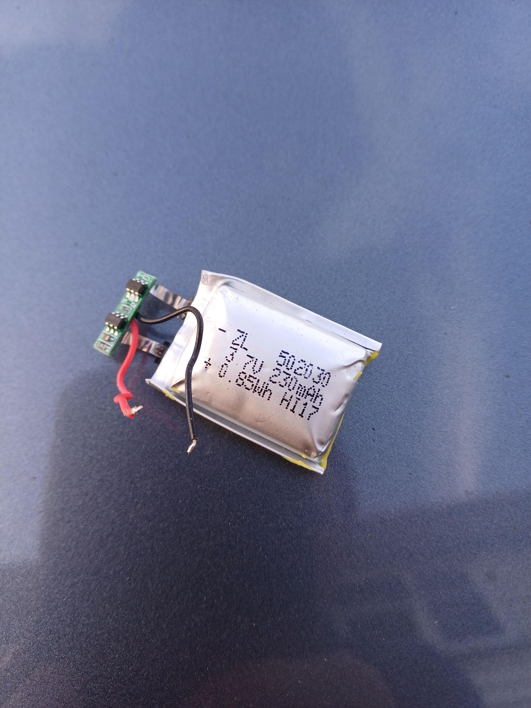
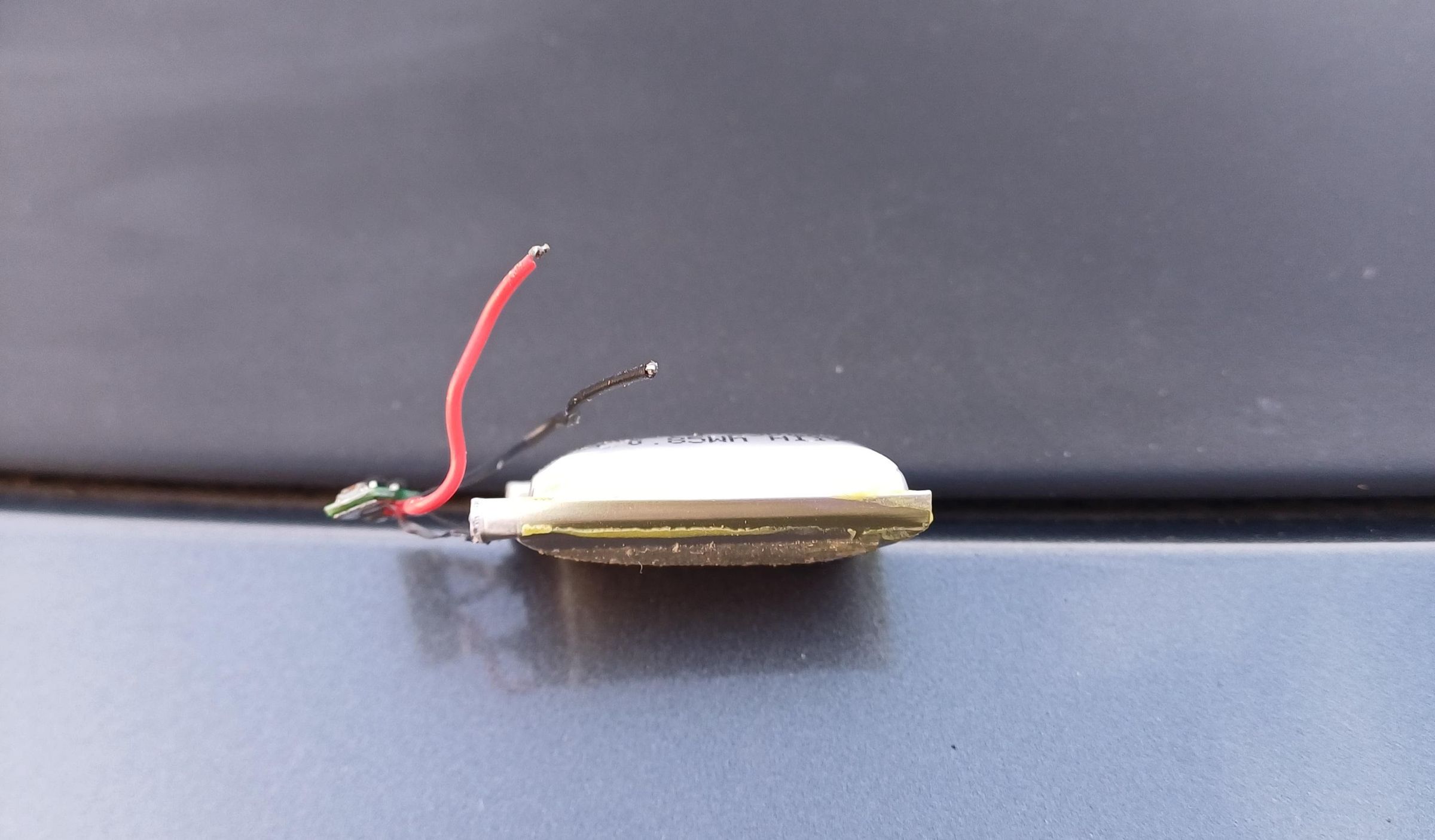
The 502030 3.7V LiPo battery is between the PCB and the front cover, and is lightly bonded to the PCB with adhesive. Peel the battery away from the PCB, exercising caution if it is pillowed (puffed) like min was. Do not pierce the battery with anything sharp. Unsolder the battery from the PCB and dispose of it according to local regulations.
The battery is 5mm thick, 20mm wide and 30mm long and has a built-in protection circuit, the original battery was 230mAh, the replacement I bought online was 250mAh. It cost about $8.
Install New Battery
Solder the new battery onto the PCB, observing the polarity and attach the battery to the PCB with double-sided tape. There is a large white rectangle on the PCB indicating the correct location.
Reassemble Main Casing
.jpeg)
Assembly is the reverse of the disassembly procedure.
Ensure the speaker and microphone are placed into their slots if they were removed, and verify that the USB port and GPS socket are inserted correctly into the casing. Pushing the side buttons in the casing outward may help the PCB settle into the casing and align with the switches on the PCB. Make sure that the front cover is correctly snapped into the main casing before tightening the screws. It should be evenly flush all the way around.
Install the LCD screen into the casing.
Install the Screen Cover
New double-sided tape may be required on the LCD cover when reinstalling it. Isopropyl alcohol can be used to soften and remove old tape residue.
Reset
After assembly, it may be necessary to add USB power and press the reset button for a few seconds to get the unit to boot properly adn to charge the battery.
Install the SD card, plug in the GPS cable and screw it back on the the screen mount.