Restoring an Early 1970s Turntable
by MarceloG19 in Workshop > Home Theater
3308 Views, 34 Favorites, 0 Comments
Restoring an Early 1970s Turntable


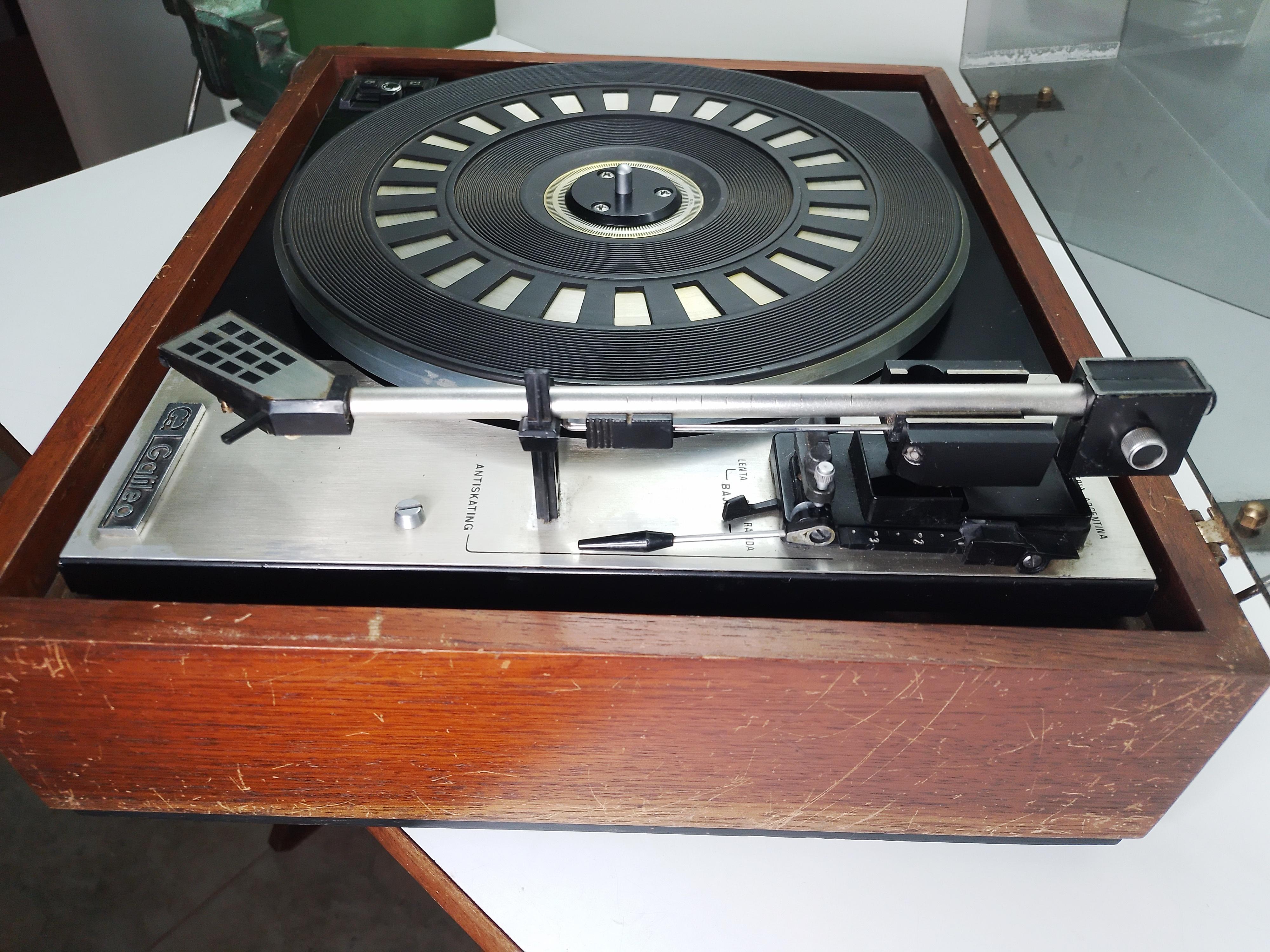
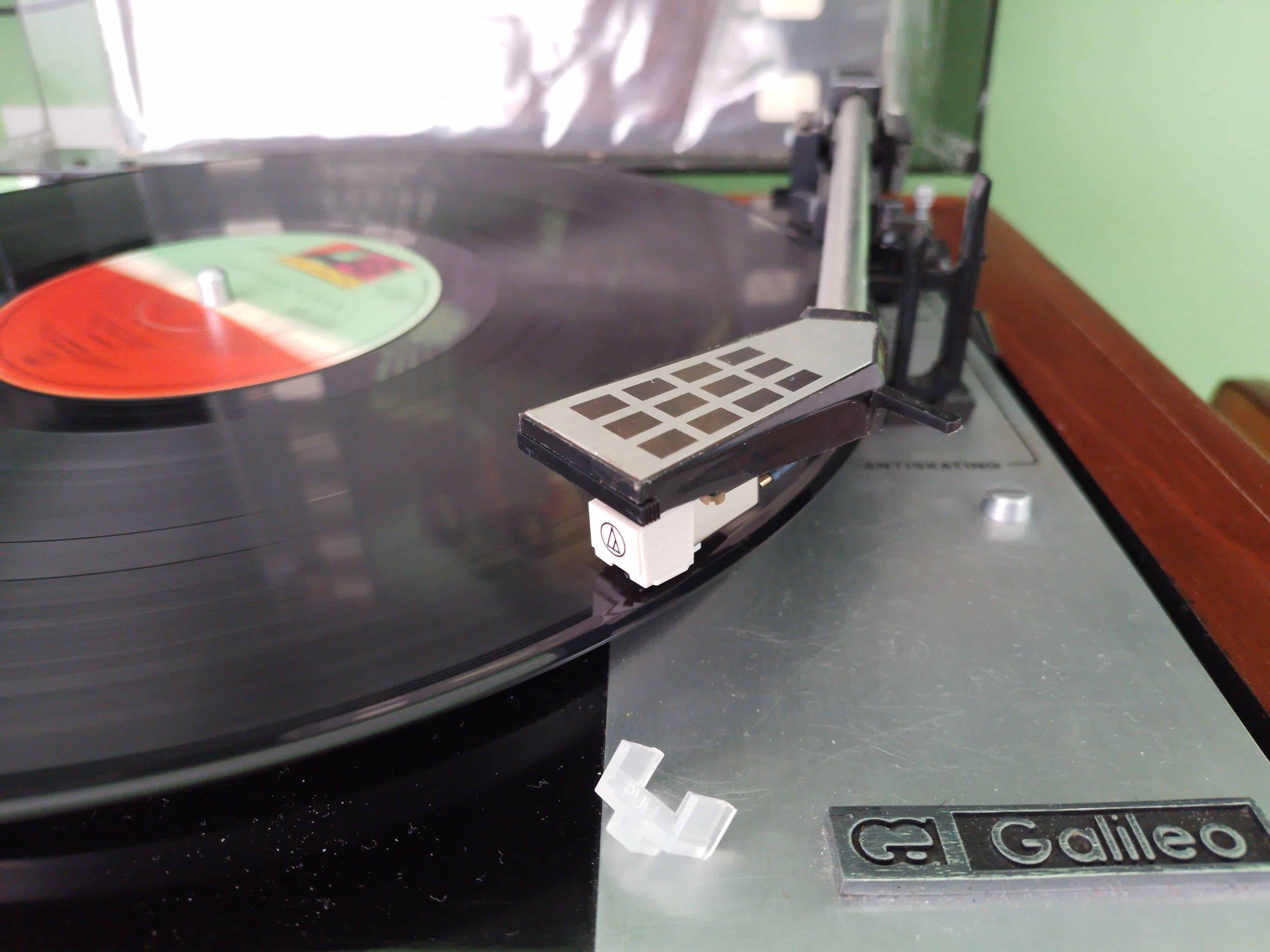
This is a Galileo turntable that was stored at my old shop for over twenty years, probably manufactured in the first half of the 1970s. The original owner sold it to me, among other old audio junk, in the late 90s, perhaps after other twenty years lying in his attic.
I've been wanting to add a turntable to my "permanent work in progress" audio stack for a while, so I preferred to restore this machine that was gathering dust on a shelf for decades instead of buying a brand new one (Well, sure there are pretty good and affordable turntables, but here in Argentina everything is ridiculously overpriced!).
Plus, for a DIYer like myself, it's much more enjoyable to rebuild, modify and give something a new life than to buy stuff off the shelf and simply use it.
Challenging my abilities and gaining new skills and knowledge in the process is part of the joy of listening music.
Supplies


I mainly use common tools, both in my modest hobbyist shop and in the machining shop at my work. Also it's very helpful to have access to a 3D printer from a friend.
Parts and supplies are both recycled and new, as well as 3D printed:
- 9mm plywood recovered from a pallet.
- Recycled cedar board.
- Recycled screws from "EL TACHO DE LOS TORNILLOS" (Screws from my junk bin :-) ).
- 2 RCA sockets.
- 300 ohm connection block from my junk box.
- IEC-320 C14 socket recovered from a PC power supply.
- IEC-320 power cord.
- Garrard C2 style Cartridge Sled (newish).
- AT3600L mm cartridge.
- ATN3600LE elliptical stylus.
- 3D printed receptacle for signal connectors.
- 3D printed bezel for c14 socket.
- 2 set of 3D printed detachable hinges for the dust cover.
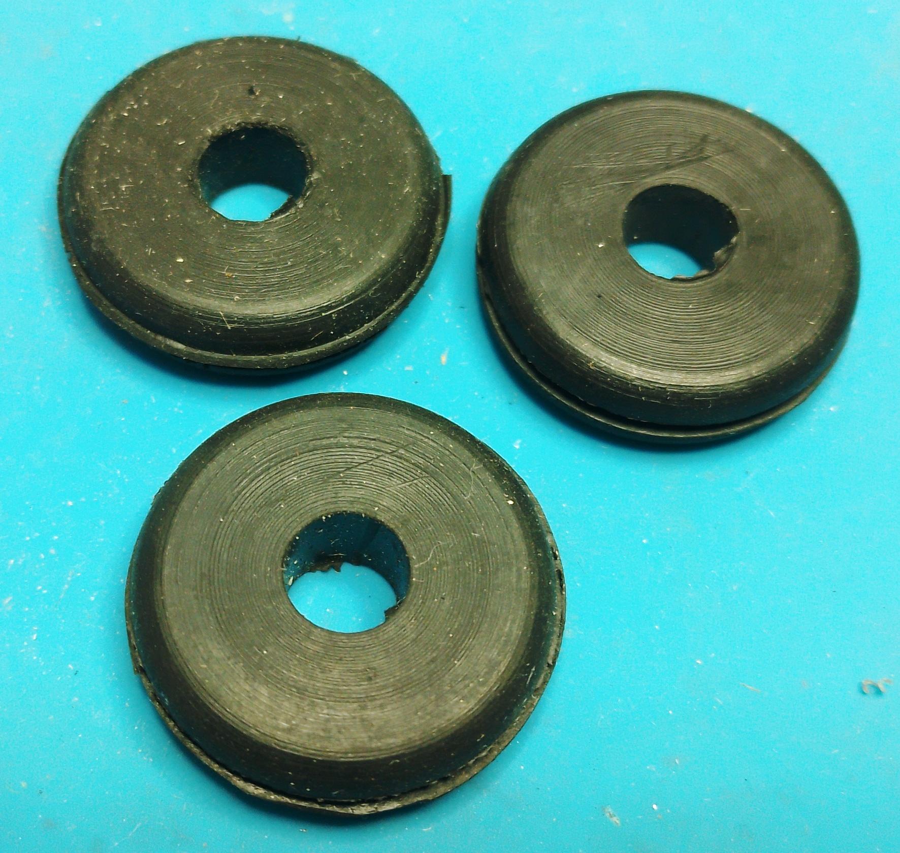
- 3 1 inch rubber grommets.
- 4 anti-vibration rubber feet with 5/16" threaded rod.
- 4 flanges with 5/16" thread.
- Self-adhesive felt pad.
- Wood glue.
- Matte black spray paint.
- Satin clear spray varnish.
- Sand paper of various grits.
- Metal polishing paste.
- Glue, acrylic varnish, etc...
Checking the Initial Condition and Disassembly


The unit itself was virtually intact. Just the effects of time, some dirt, wear on the cue lever, some rust on the dust cover hinges and minor cosmetic details.
The spindle, motor and tonearm bearings are in good condition but the lubricant grease was dry and sticky.
It was fitted with a very battered Shure M44MC cartridge without a stylus. The lower part of the headshell, a Garrard C2 style cartridge sled, was in a bad shape too.
The original power cord was in dangerous condition.
Rubber parts -Platter mat and idler wheel- were in good shape for their age, the idler wheel needed to be re-surfaced to remove the slippery, glazed surface.
The original signal wires of the tonearm are rusty and stiff, so they need to be replaced.
The cue lever was wobbly due to wear, causing the cue mechanism to act unevenly.
Not too bad! :-)
The Chassis: Cleaning, Lubing, Repairing, Wiring


The chassis and its parts were cleaned, old grease was removed and replaced with fresh lithium grease.
The suspension springs were removed from their mountings. They were shrouded with 3mm silicone tube instead of using plastic foam, then reinstalled in place and the attachment points reinforced with epoxy.
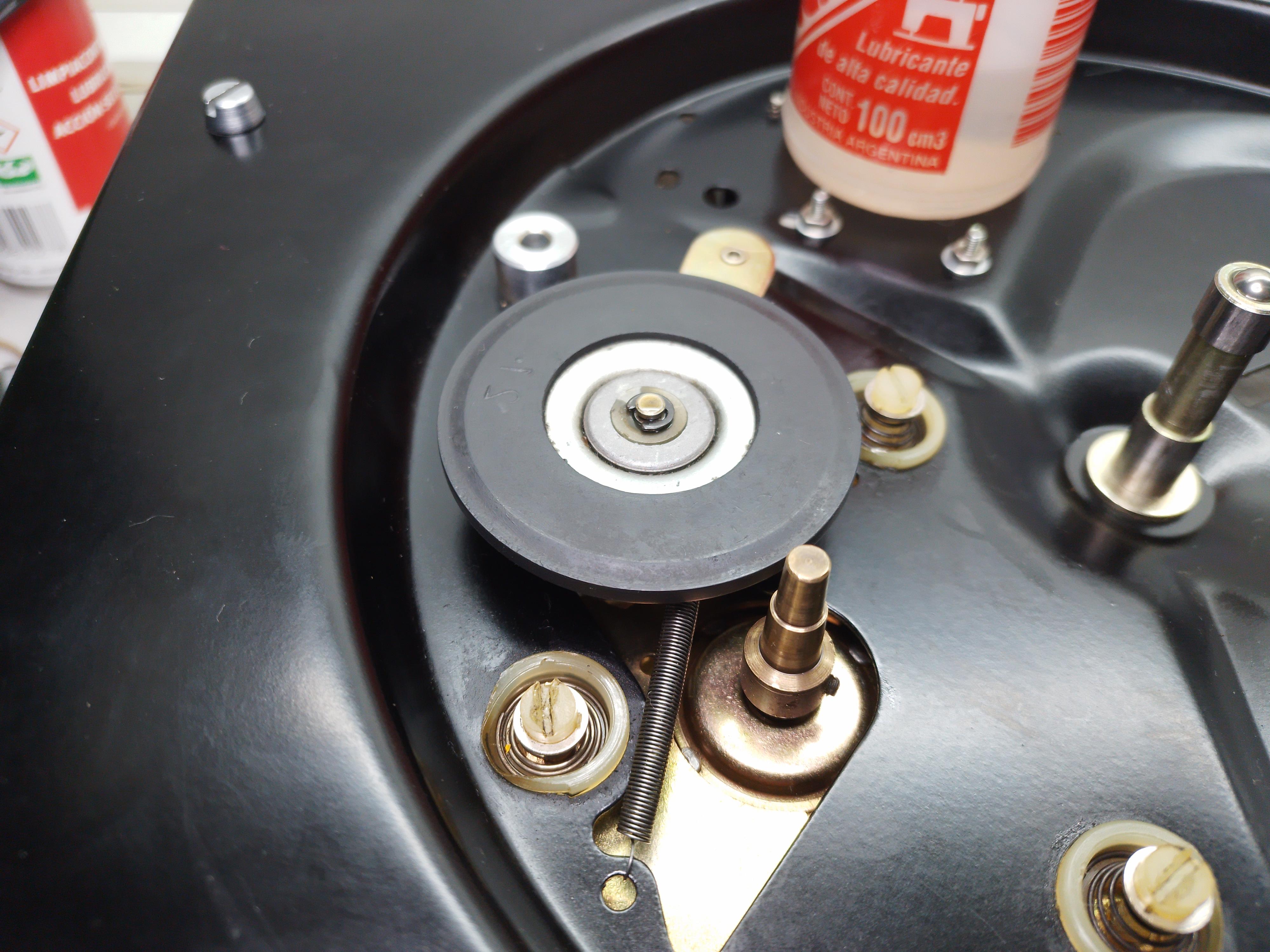
The idler wheel outer rim was sanded to remove the old glassy surface, then cleaned with isopropyl alcohol, its bearing oiled and reinstalled.
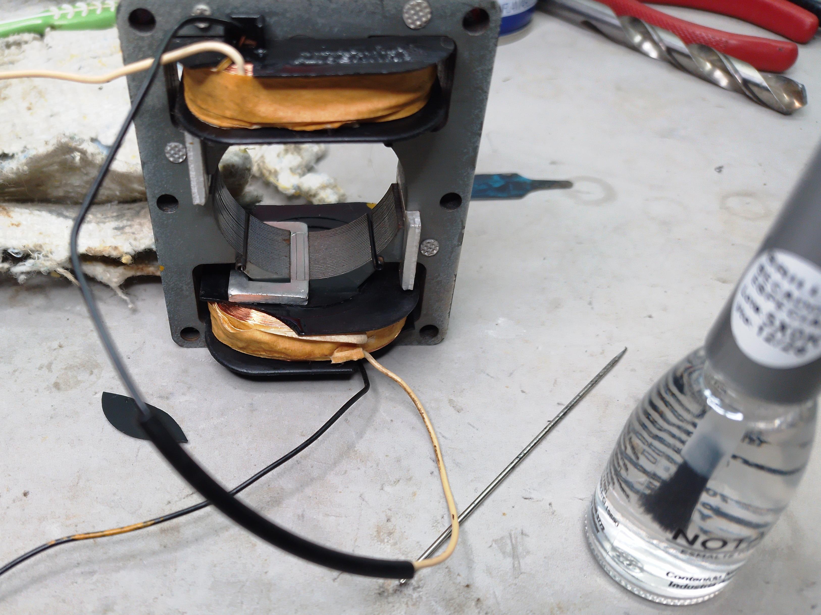
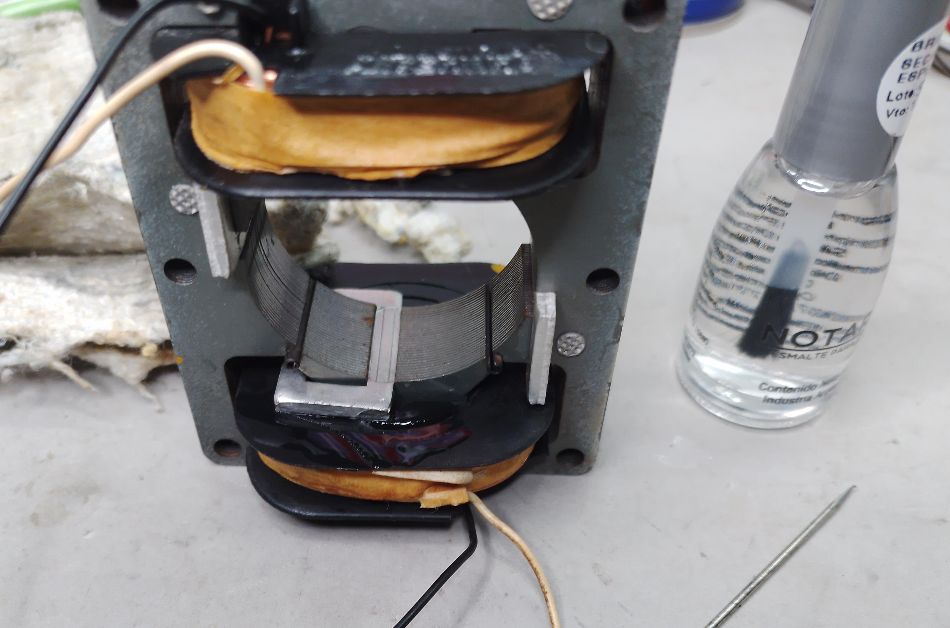
The motor was disassembled, cleaned and its bearings oiled. The coil spools had some broken parts because the plastic was dried out. Loose parts were glued together and exposed wires were protected with acrylic lacquer.
Then it was reinstalled and wired with new cables.
The platter and rubber mat were washed and cleaned. A polish restored its shine.
The spindle was lubricated with lithium grease.
Now everything looks shiny, moving parts work freely and platter turns effortlessly and quietly!
Restoring the Tonearm


The tonearm was completely disassembled and cleaned.
The internal lead weights of the counterweight and the rubber skid on the cue lifter were glued back in place.
The attachment of the upper part of the headshell had some slack after fifty years, this affects the stability of the alignment and azimuth of the cartridge which can cause deterioration and distortion of the sound.
The electrical contacts of the headshell were badly corroded and it took some effort to polish them and remove the rust.
The lower part of the headshell (Garrard C2 style Cartridge Sled) was as battered as the installed cartridge, beyond repair. It was replaced by an unused old part bought on line (it is in good shape, but its contact leads were also corroded).
Signal cables were replaced with new OFC Teflon coated wires (ludicrously expensive in Argentina), the DIN socket was replaced too. Now the entire signal path is new now, corroded contacts and old, oxidized wires have negative effects on the sound quality. A fifth wire connected to the tonearm body was added to ensure shielding (originally the tonearm was grounded via the bearings, which is not a very reliable grounding method).
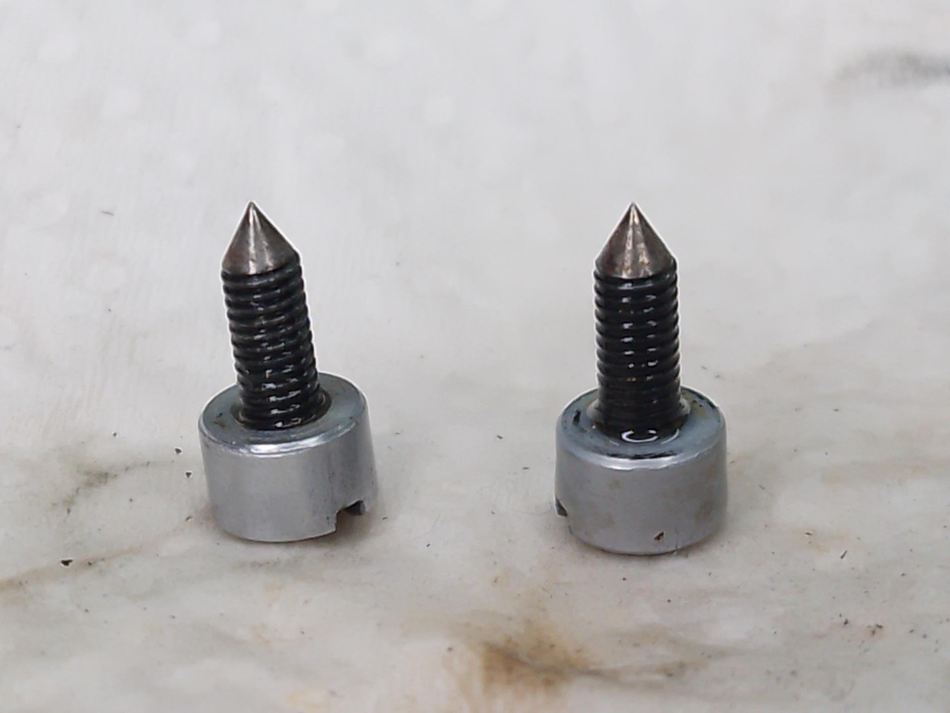
The cue mechanism was among the most worn parts of the turntable. The cue lever had severe lateral play, resulting in inaccurate cue action (to be honest it was partly caused by wear and tear and partly by a flawed design). The lever pivot bore was sleeved to eliminate the lateral play by making a tighter fit to its shaft. The cue ramp had an ugly grove caused by the friction between the stainless steel screw on the soft aluminiun body. The solution was to file down the worn area and wrap it with a 0.25mm brass strip. A quick spray of black paint made it look brand new!
All parts were reassembled, bearings lubricated with light machine oil and reinstalled into the chassis for initial performance test. The result has been very positive so far!
The Plinth: Doing Some Wood Work


WARNING!
Power tools can be potentially dangerous if improperly used, please always follow proper safety procedures.
Carpentry is not in my field of expertise, my equipment for this kind of work is basic, not to say rudimentary. In fact, I haven't done any kind of woodworking for at least thirty years.
It was the most labor-intensive stage of the project and the most challenging for my modest skills.
The box was in excellent condition other than the scratches. The walls are made of solid cedar wood (not veneered), to my grateful surprise! However, the bottom was made of cheap, thin 3mm plywood, which made the plinth resonant like a tambourine. It was evident as a huge amount of sub sonic noise (rumbling) during testing after mechanical maintenance was performed and reassembly.
The top tray where the machine sits was made from an equally cheap 9mm particle board with veneer. Such structure was so flimsy that it bent down under the weigh of the turntable over the course of half a century disrupting the ability to remain level.
The cabinet feet, just four small pads of perished rubber, never provided adequate isolation from external vibrations.
The goal of this step was to improve the plinth from both a technical and aesthetic point of view.
The top tray, plywood bottom and old rubber feet have been permanently removed and replaced with new parts.
The bottom was replaced with two layers of 9mm plywood glued together. The material came from a pallet (right, eucalyptus plywood is not the noblest stuff, but it is free and good enough for the task).
Before gluing everything together, holes were drilled for the new feet, a recess to make room to the motor and two holes to give access to the travel lock tabs.
The two layer of plywood were glued together using the threaded feet as alignment jigs, then the assembly was pressed down with a heavy weight and the glue allowed to dry for 24 hours. Then the new bottom was glued on with a strong epoxy resin. It was allowed to cure for another 24 hours, holding everything in place by pressing down the on the assembly with heavy weights.
The box was sanded to remove excess epoxy and old varnish.
The top of the box was modified using cedar sticks cut from an old board. The idea was to reduce the gap between the plinth and the perimeter of the chassis. The idea was to give the plinth some resemblance to the European turntables of the time such as Lenco or Thorens.
The suspension is now supported at the bottom by three solid pine wood blocks. Adding mass and stiffness to the plinth by installing the new thick bottom plate is an attempt to reduce vibrations and rumble.
The new threaded feet are a controversial choice because they are intended to isolate heavier machinery (their rubber is not as soft as I would like), but it is a step forward from the old cleats. Additionally, the threads allow for more precise levelling the turntable.
The modification on the top of the plinth gives it elegance.
Adding Some Extra Isolation to the Suspension Springs


Since the manufacturer built this turntable from cheap record changer parts, the suspension springs are attached directly to the chassis. This allows the external noise to be transmitted from the plinth to the chassis without any obstacles. Other turntable manufacturers of the time placed rubber spacers between the suspension springs and the chassis to provide some isolation from vibrations transmitted from the base. My solution consisted to add three modified 1" rubber grommets beneath the springs.
Three 8mm plastic dowels were used as locators to keep the suspension centered on the supports. Some cuts of eva rubber served as spacers to keep the top of the turntable flush with the top of the plinth. This is an interim solution, the dowels and the spacers will soon be replaced with adjustable threaded supports.
Making Holes for the Connectors


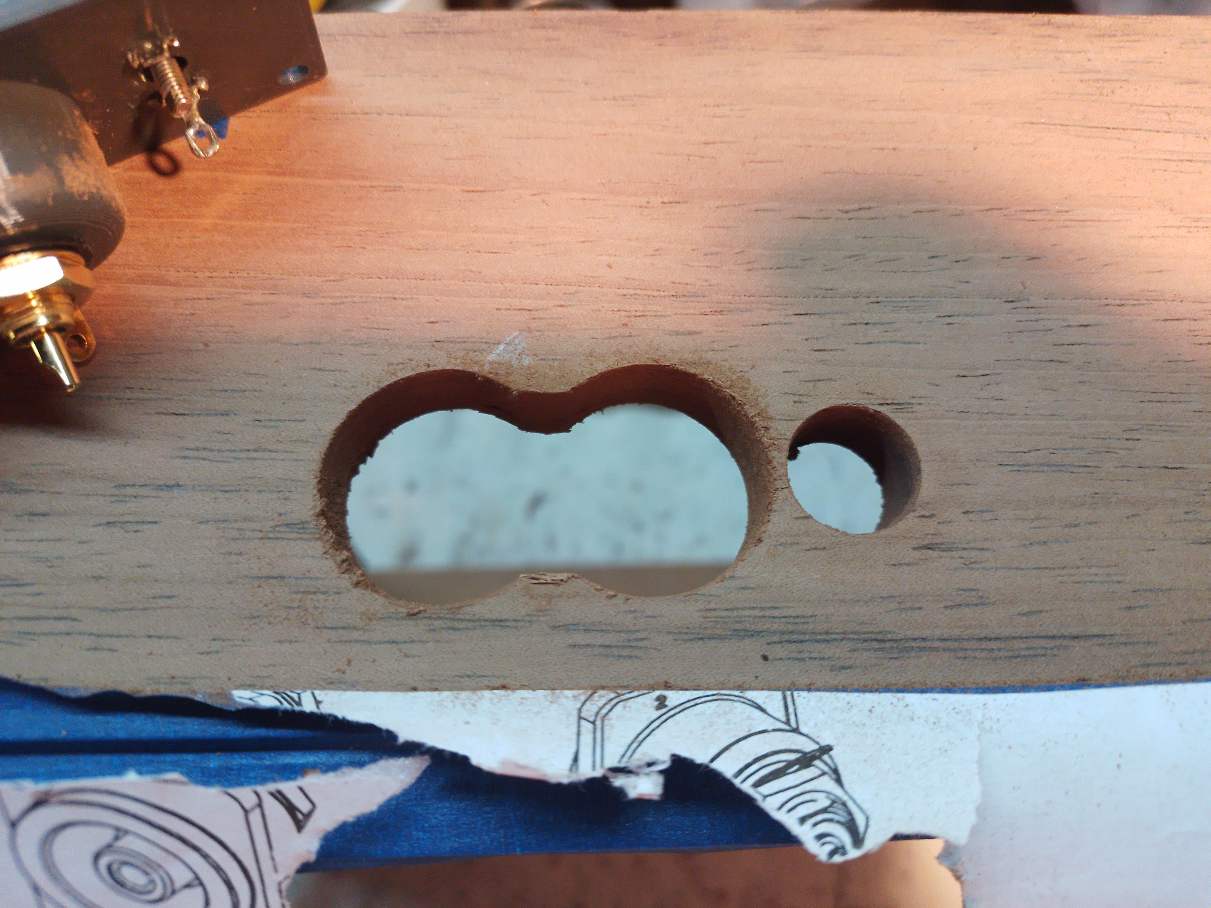

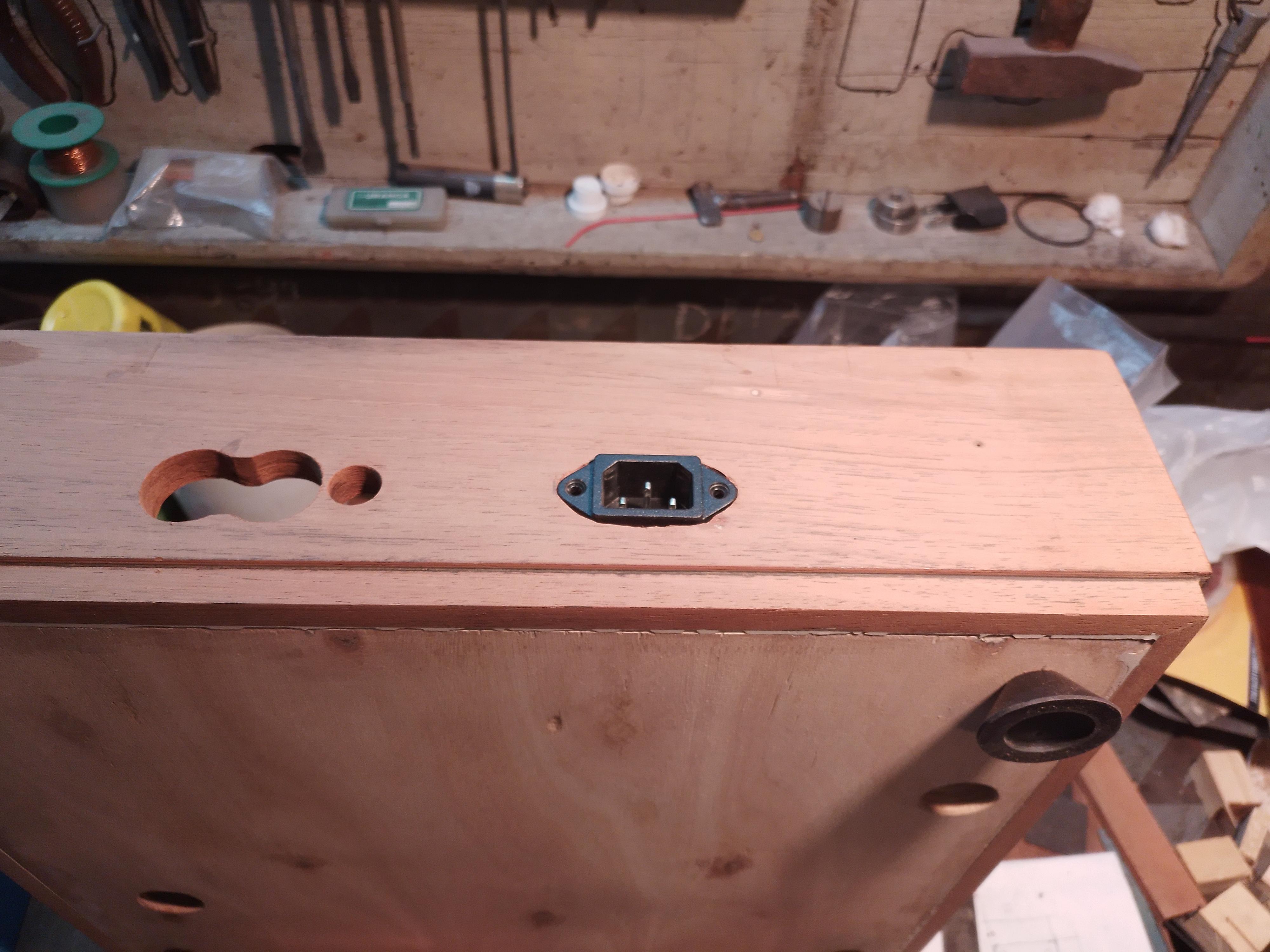

The back wall of the plinth was drilled to install the new connectors. The RCA and ground jacks were mounted on a 3D printed housing. The IEC connector was embellished with a 3D printed bezel.
Sanding, Painting, Varnishing


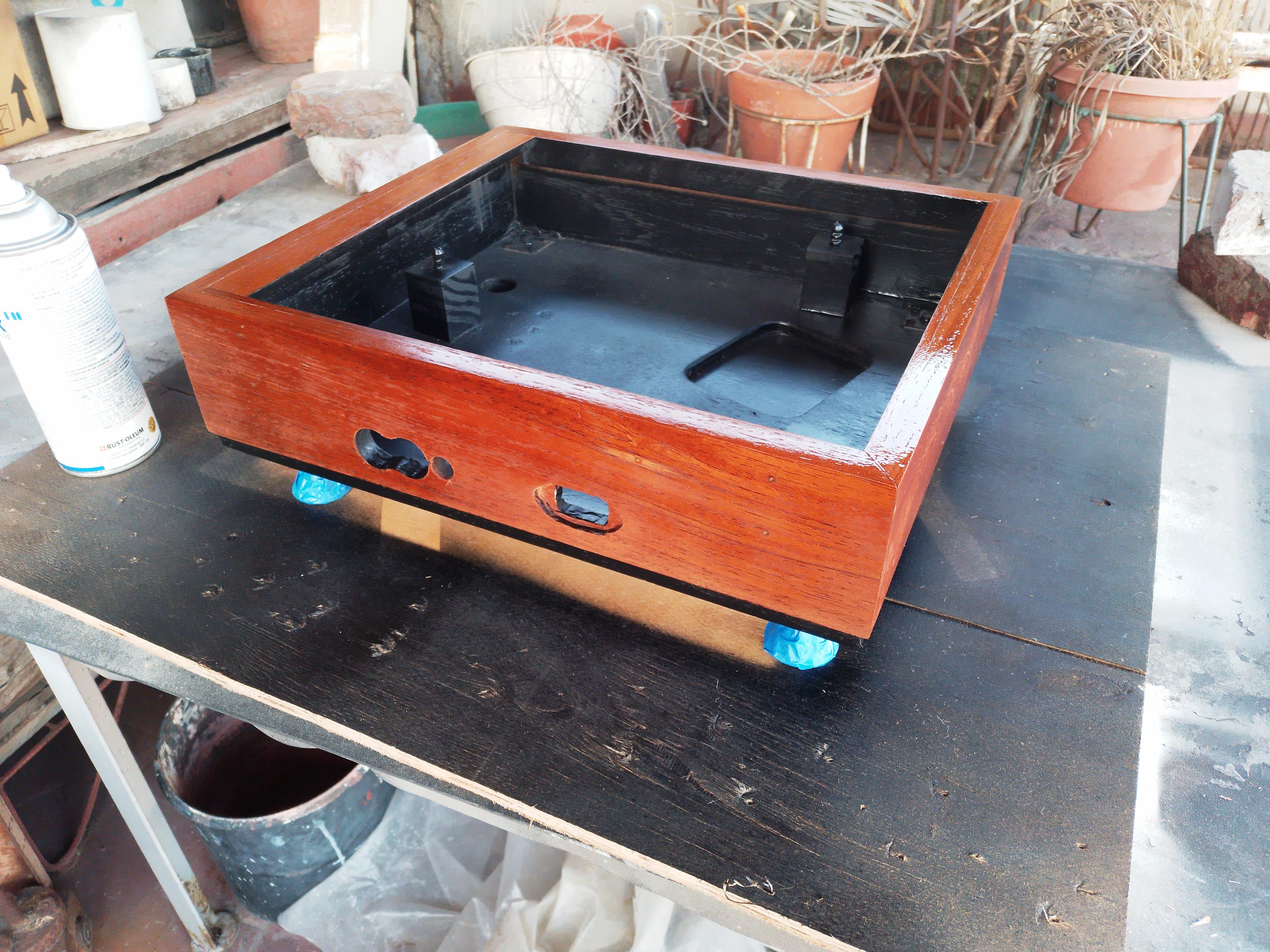


After cutting, drilling, modifying and gluing the plinth to the new style, it was sanded and polished. The bottom and inside of the box were painted matte black. Finally it was coated with four layers of clear satin varnish.
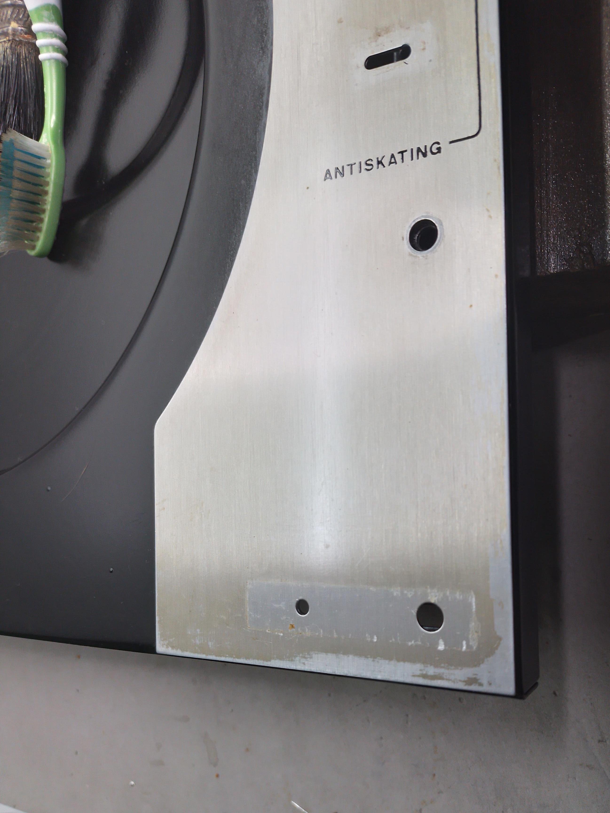
Fabricating a Pair of Tabs for the Travel Lock


These simple parts were made from a strip of aluminium, painted matte black and installed inside the plinth with screws.
These plates are part of the travel lock mechanism.
The Dust Cover: Cleaning, Cutting Down, Polishing


This was the most challenging stage.
A cleaning and polishing would have been an easy job, since the acrylic lid was in pretty good shape for its age. But I wanted to somehow improve the aesthetics by trimming the side walls of the top cover, a risky choice.
50+ years old acrylic can be a very brittle material.toolmy drill press adapter, my drill and some clamps. The key tool to achieving a successful job was an HSS cutting disk with fine, straight teeth. This prevents the material from cracking.
Then sanding out the scratches and polishing to restore the shine of the dust cover was a straight forward job.
Final Assembly, Calibration and Adjustments


Having cleaned-fixed-lubed-polished-drilled-modified-3D printed-painted-varnished each part as required, it was time to put all together into a working turntable.
Connectors were wired and secured in place with screws as well as the new 3D printed hinges.
Adhesive felt pads were placed on the bottom of each threaded feet and each bottom corner of the dust cover.
Then it was possible to connect the turntable to the wiring and finally put it in place!
Job done! however...
Prior to play records for the first time, the turntable needs some set up.
Obviously the first thing to do is to place the machine on a flat, firm and leveled surface, then connect the power cord, the signal interconnects and the ground wire.
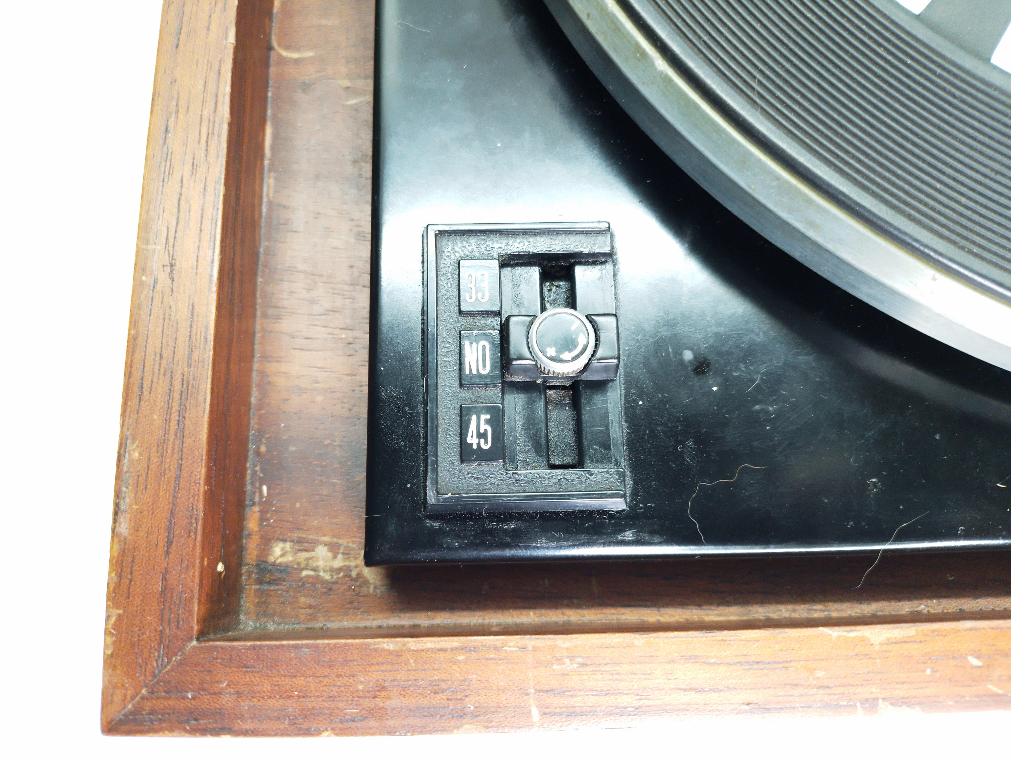
Then turn the motor on and check the RPM, this unit has a trim knob on the power and speed selector to fine-tune the speed. To achieve this adjustment, a strobe disk is needed, a small one is built into the platter mat. This is good enough, but a larger disk helps achieve more precise setting. Pro versions are commercially available, but you can download one from the internet and print it. Also there are smartphone apps designed for this purpose.
Check the turntable is level, this is important because level deviations affect the accuracy of the stylus tracking and distort the sound. A spirit level is a convenient tool; corrections can be made using the threaded feet.
Having the RPM and the turntable level have been adjusted, it is now time to set up the tonearm:
First, set the tacking force and anti-skate weights to zero then move the counterweight until the tonearm balances horizontally.
Then, slide the tracking force weight to achieve the required stylus pressure using a suitable scale.
The anti-skate adjustment require the use of a flat, smooth plastic disk. First set the anti-skate weight to approximately the same value as the tracking force using its numbered scale, turn on the platter, carefully place the stylus on the disc and check the lateral movement of the tonearm. If the tonearm tends to slide toward the center of the disc, slide the weight to a higher number of the scale to increase the anti-skate action. Conversely, if the tonearm slips outwards, the anti-skate action is too strong and needs to be reduced.
This procedure should be done by small increments until the tonearm is stable.
Now the turntable is ready to play records!
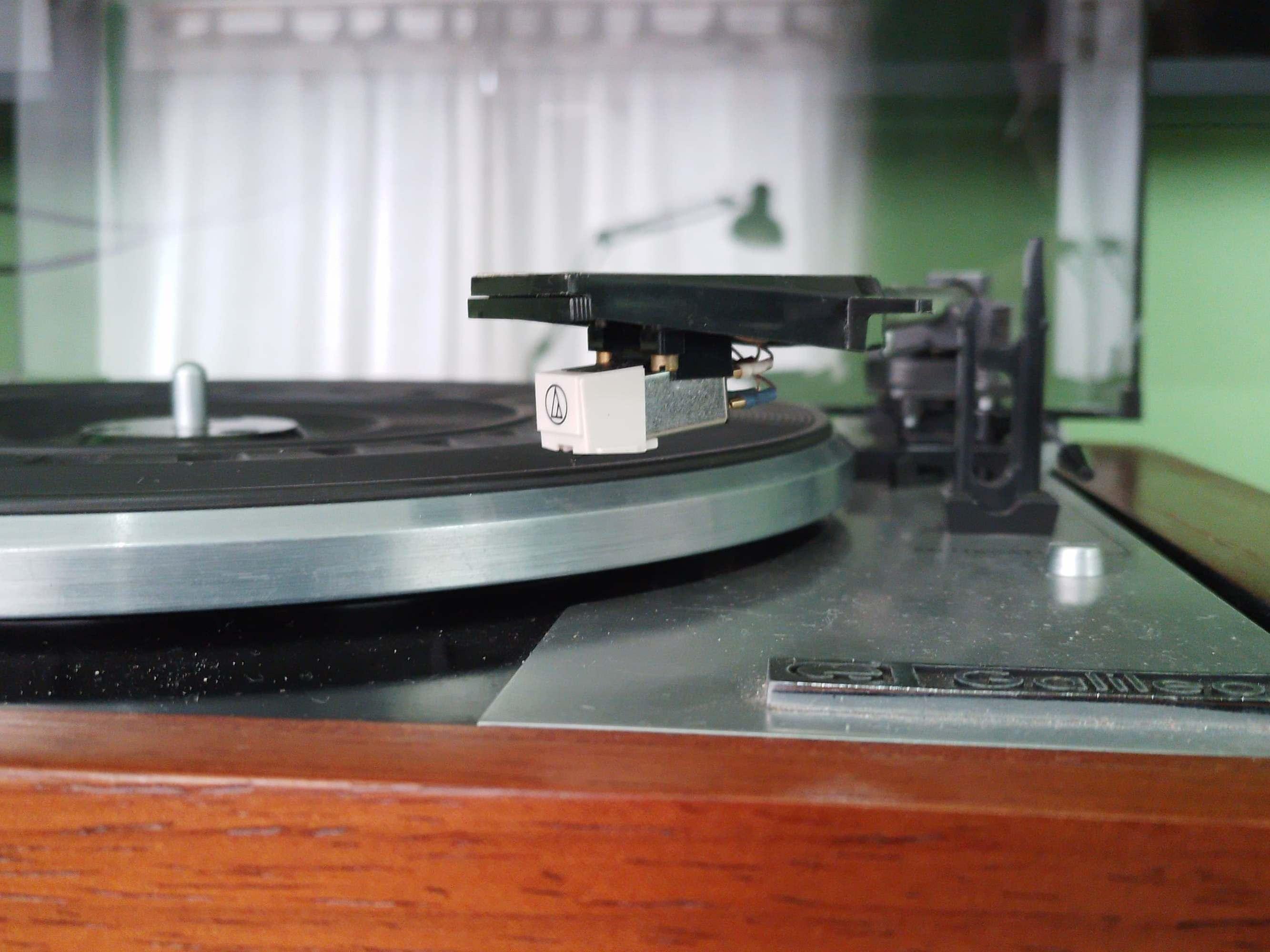
Enjoying the Music!


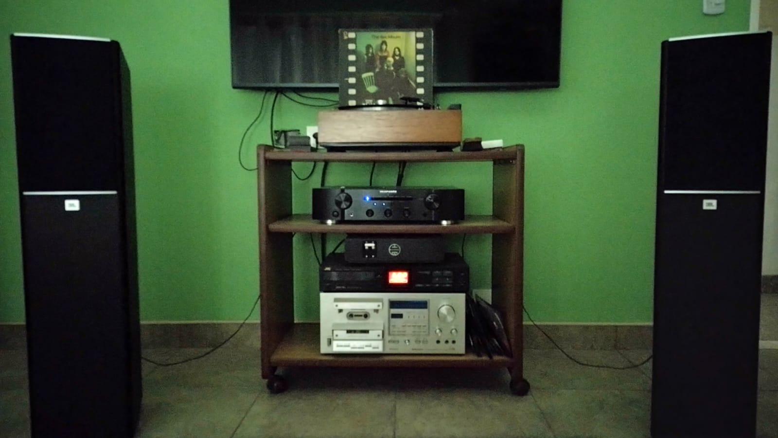
Now is time to get a bunch of records and enjoy the music.
The end result was mostly satisfactory, the RPMs are stable and the affordable AT-3600 cartridge was the right choice for this turntable. There are still a number of issues to be fixed, such as some ringing at the outer side of the platter, a little of electromagnetic hum induced from the motor to the cartridge at the end of the record and other technical details. But it may be part of another future project.
Special Thanks
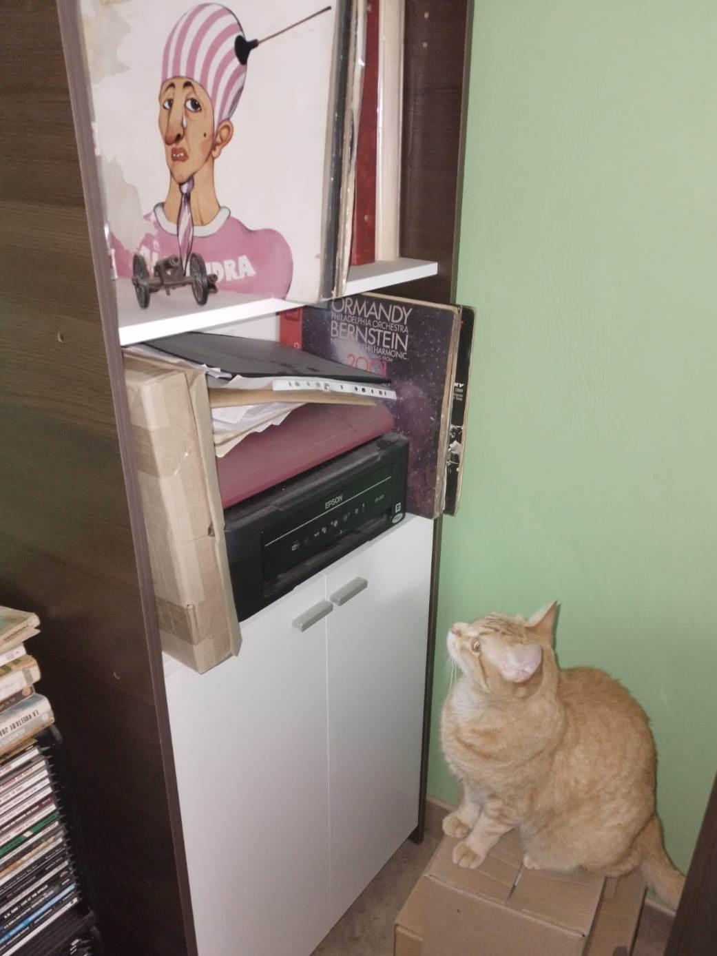
It's always good to be grateful to the people who give you support and help, so many thanks to Luis and his 3D printer; Leonardo "El Pana" for his help, support and printed circuits; Abigail, for her loving support and my four-paws-furry-friends for their fun and companionship!