Retro Gaming on a ESP32-S3...Inside a Controller. Outputs to HDMI.
by DynaMight in Circuits > Electronics
1735 Views, 13 Favorites, 0 Comments
Retro Gaming on a ESP32-S3...Inside a Controller. Outputs to HDMI.
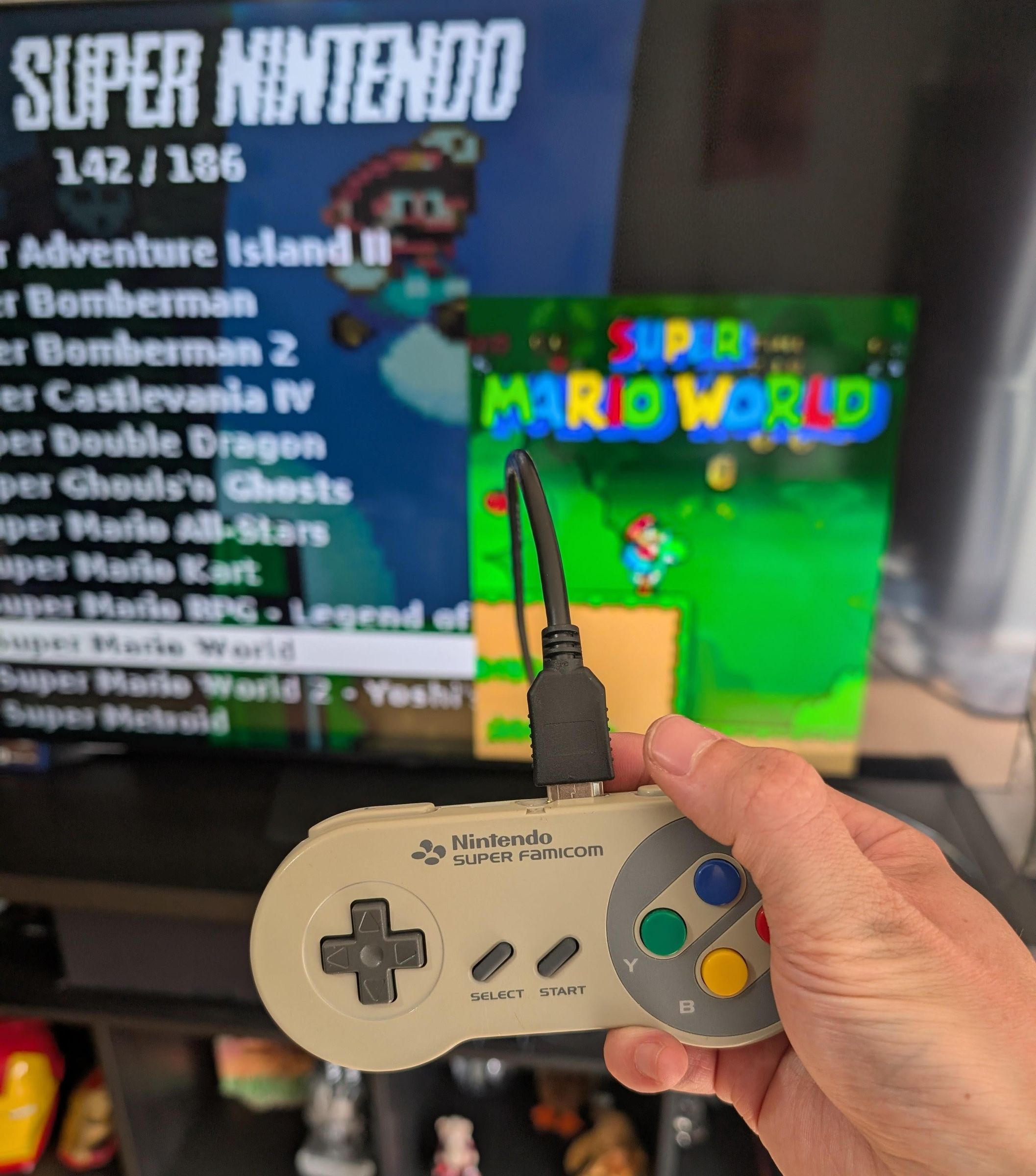
I had been working on some other projects such as the amazing PicoNES, which outputs to HDMI for a console like experience.
I was wondering if the ESP32 could do something similar, I kinda knew the answer and it was a no, not even the newer ESP32-P4 however I also came across a project by fliperama86 which used a RP2350 to receive SNES RGB signals and output over HDMI.
So I started to wonder, could the RP2350 receive SPI signals designed for a LCD display and then convert that to HDMI... I cant code but thankfully in 2026, theres AI to make anyone a 'coder' or at least have the possibility to have something create code for you. So I got some example code and asked the question, AI said it was probably possible but would be tight.
I set AI going, it wasnt clear sailing, lots of blank screens, crashes, panics, then some sync for a second followed by blank again. Lots of back and forth, flashing, retesting. We did get some semi stable image after a while so then started working on sound, this actually turned out harder than the video as Retro-Go uses a few different sample rates and I didnt want to start amending every emulator. It took a lot of trial and mostly error but we did get every scenario covered.
In the end, we got a solid 60fps 640x480 HDMI image with sound that outputs to your TV. So that then begged the question, what do I put it in? Retro-Go doesnt really have any external control options for controllers like NES, SNES, PSX or USB so felt like a console like device was maybe more work, which then made me think that maybe I'll just put it inside an actual controller!
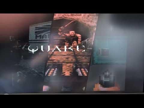
The original test device was actually a NES controller (happy to share the gerber if anyone would prefer the exact same device but in a NES controller instead, comment below), but I felt it lacked some buttons with only A/B and Start/Select, Retro-Go would expect another 2 buttons, but it did at least allow me to test it all worked plus the ESP32-S3 can run quite a few classic 90's ports like Quake, Duke3D etc. So the next step up was ofcourse the SNES, 4 action buttons, start/select and L/R!
The actual PCB and components required are fairly minimal since I didnt bother with a battery etc as it will always need to be plugged in via HDMI at least! You can actually power it directly from HDMI via a 5v injector!
Not sure what this device will support? Heres a rough list
Consoles: NES, SNES (not perfect), GB, GBC, GBA (not perfect), Game&Watch, SMS, GG, MegaDrive (not perfect), PCEngine, Lynx, MSX, Atari 2600.
Ports: Doom (1&2), Duke3D, Quake, Rise of the Triad, Wolf3D, Cannonball (Outrun), Celeste, Tomb Raider.
So if a retro console in a controller takes your fancy then look below on how to build it!
Supplies
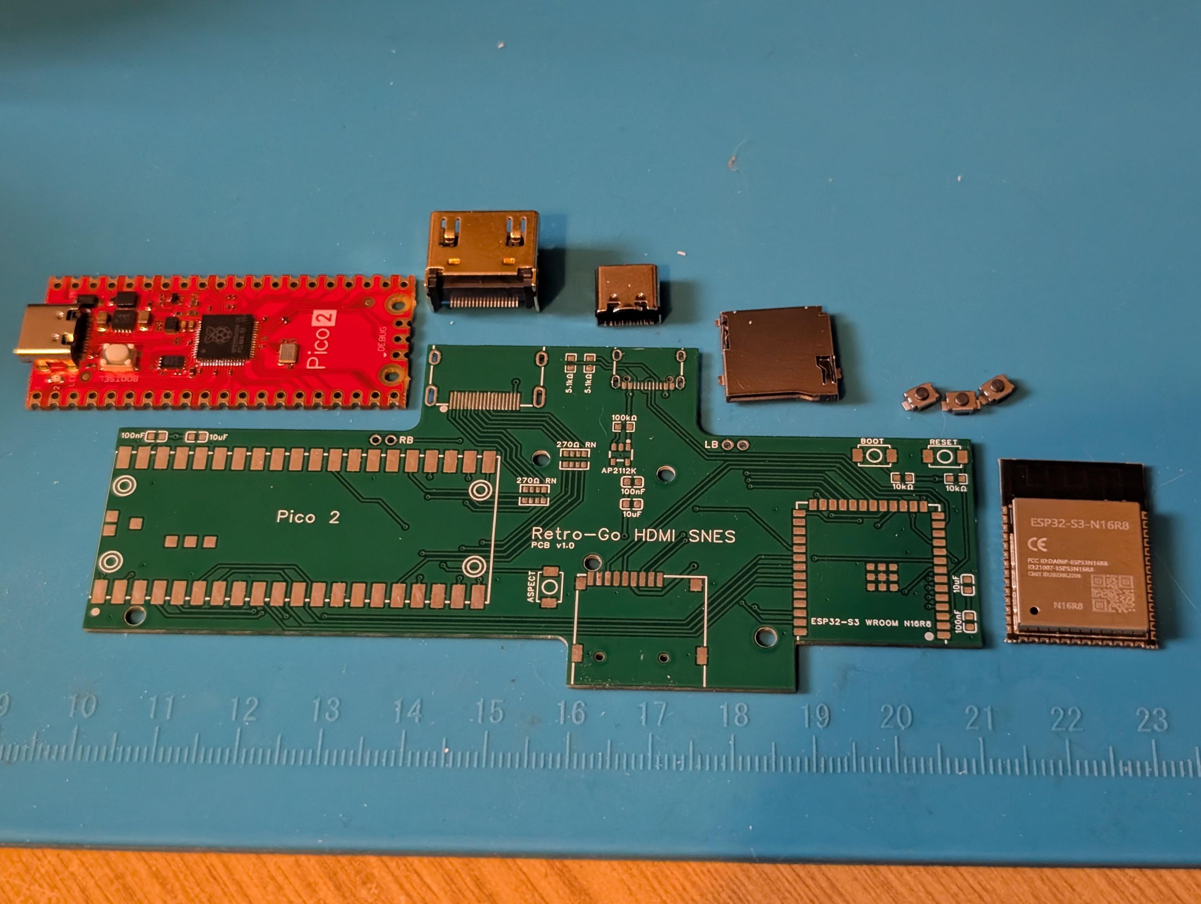
First thing you'll want to order is the PCB, you can download the gerber HERE, upload this to your chosen PCB supplier (JLC or PCBWay are both fine). I ordered mine at 1mm because that matched the aftermarket controller PCB, however the original SNES PCB's are 1.6mm so order depending on what you expect to use.
Next you'll want a controller, either an original SNES controller or an aftermarket one. I have tried both, theres good and bad things about both. Aftermarket is probably cheaper but honestly, it felt very cheap (mostly due to the weight) even if the button feel wasnt too bad. An original controller has negatives as well, it'll probably cost more (especially for a nice clean one) and potentially could have issues due to age and use, you dont know how many hours have been put into the membranes, so may need to be replaced else you'll have poor button feel. If you want to buy an original, theres plenty of places such as shops locally or online places like eBay. Below is a link to an aftermarket one.
SNES Controller (aftermarket): https://www.aliexpress.com/item/1005006420383011.html (USB ones also tend to be the exact same shell)
The rest of the components required:
ESP32 S3 N16R8 (No antenna): https://www.aliexpress.com/item/1005008168727665.html
RP2350 (can also use an official Pico2): https://www.aliexpress.com/item/1005008117237405.html
Quick note regarding RP2350's, I originally used a popular Red RP2350 however I noticed a hum/whine, related to coil whine. It doesnt cause any issues, the one isnt above doesnt have this, nor does the original Pico 2.
AP2112K-3.3 voltage reg: https://www.aliexpress.com/item/32998839398.html
HDMI Ports: https://www.aliexpress.com/item/1005001412266648.html
MicroSD Slots: https://www.aliexpress.com/item/1005001331379046.html
USB-C Ports (16 pin): https://www.aliexpress.com/item/1005007079016649.html
Tact Switches (3X4X2mm 2Pin): https://www.aliexpress.com/item/4001317902663.html
270 Ohm resistor array: https://www.aliexpress.com/item/1005005580079760.html
0603 Resistor kit (0603 720pcs 36 values): https://www.aliexpress.com/item/1005006198053993.html or separately (10k, 5.1k & 100k): https://www.aliexpress.com/item/1005001436923851.html
0603 Capacitor Kit (0603 16Value 320pcs): https://www.aliexpress.com/item/1005002761630440.html or separately (100nF & 10uF): https://www.aliexpress.com/item/32966526545.html
M2 & M2.6 Self tapping screws (6mm): https://www.aliexpress.com/item/1005002417296996.html
(Optional, see step 5) HDMI 5v injector: https://www.aliexpress.com/item/1005010195119341.html
Building the PCB
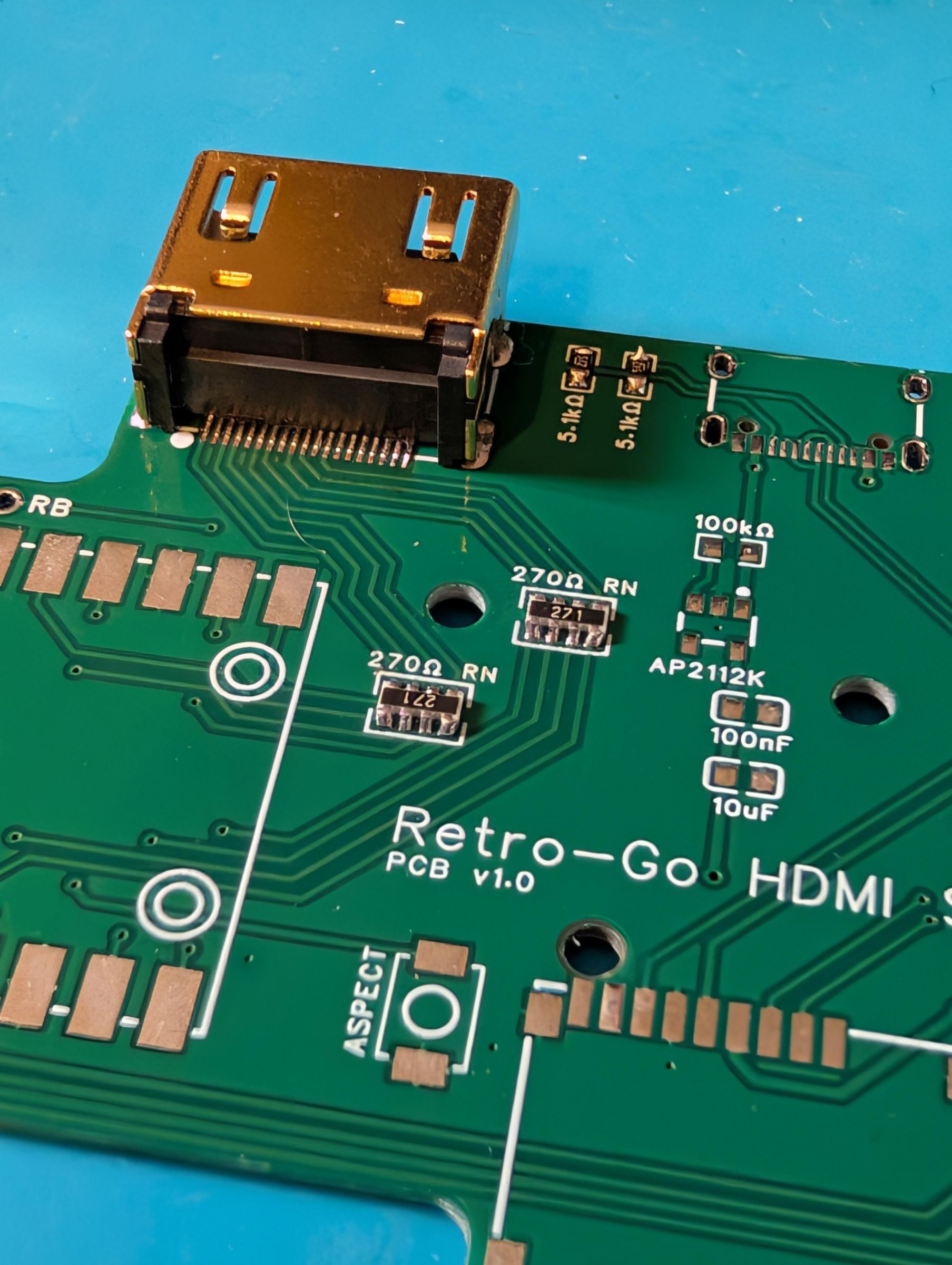
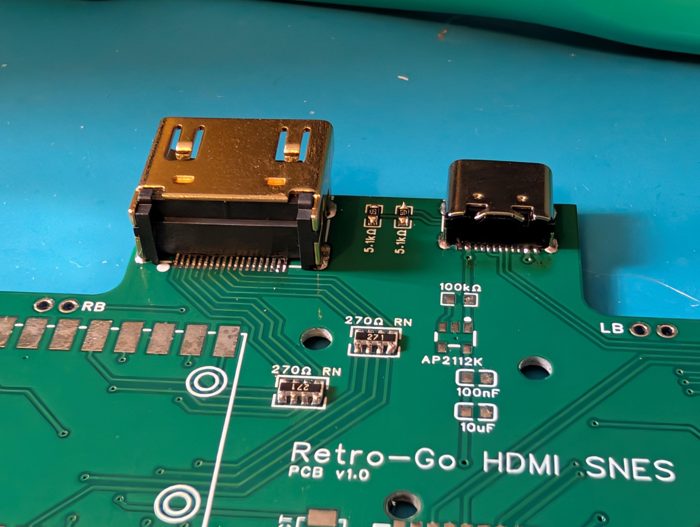
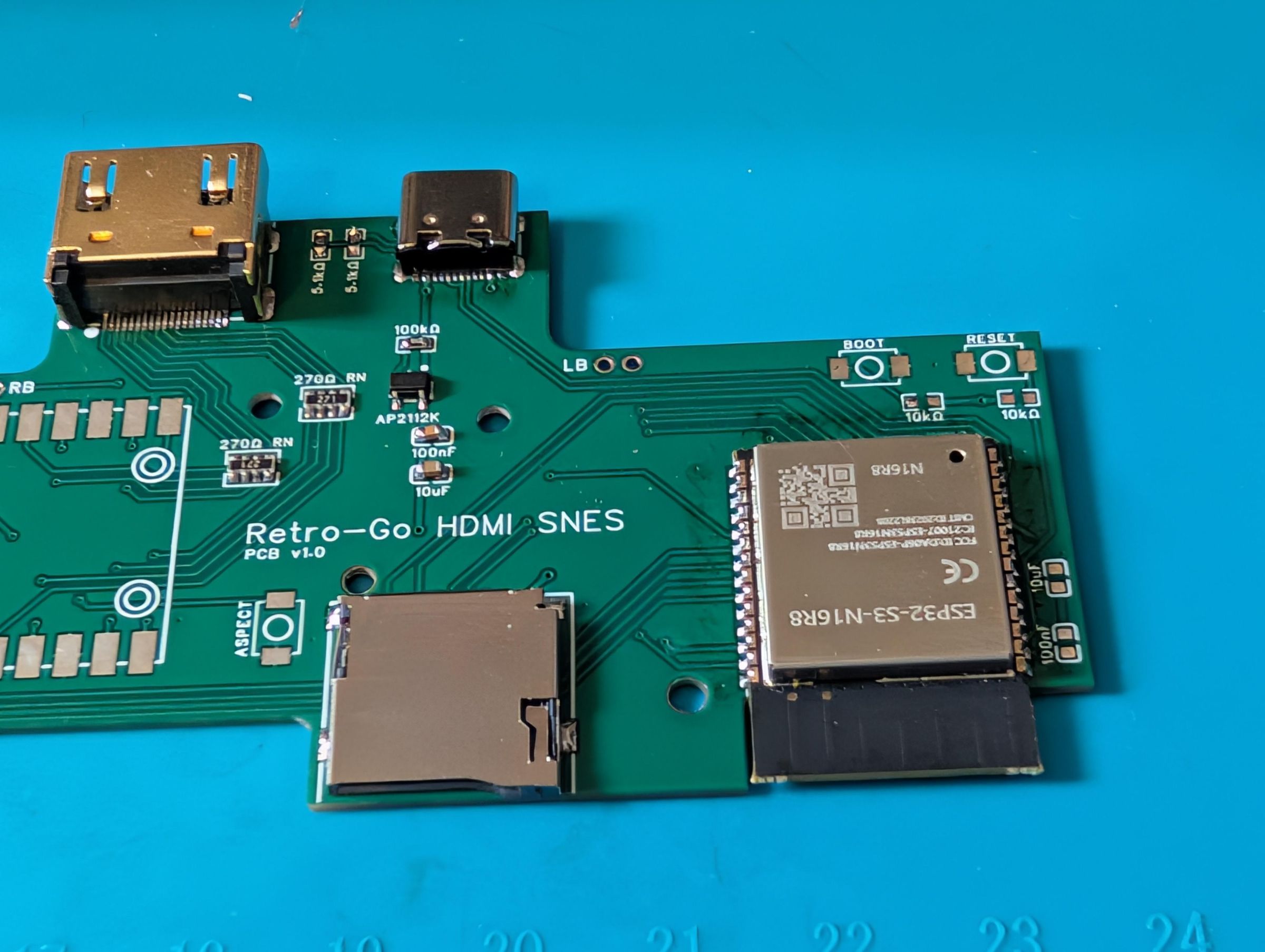
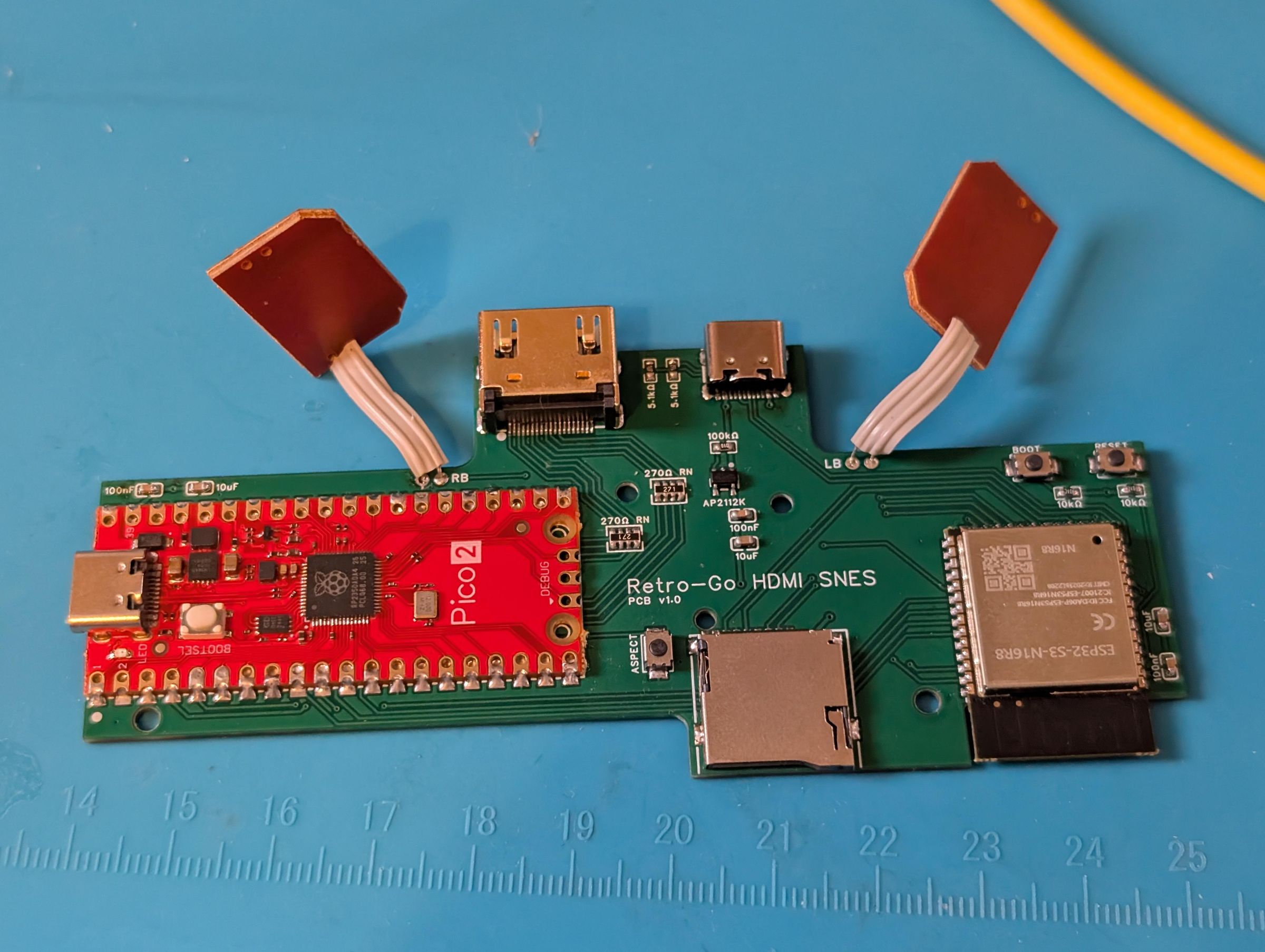
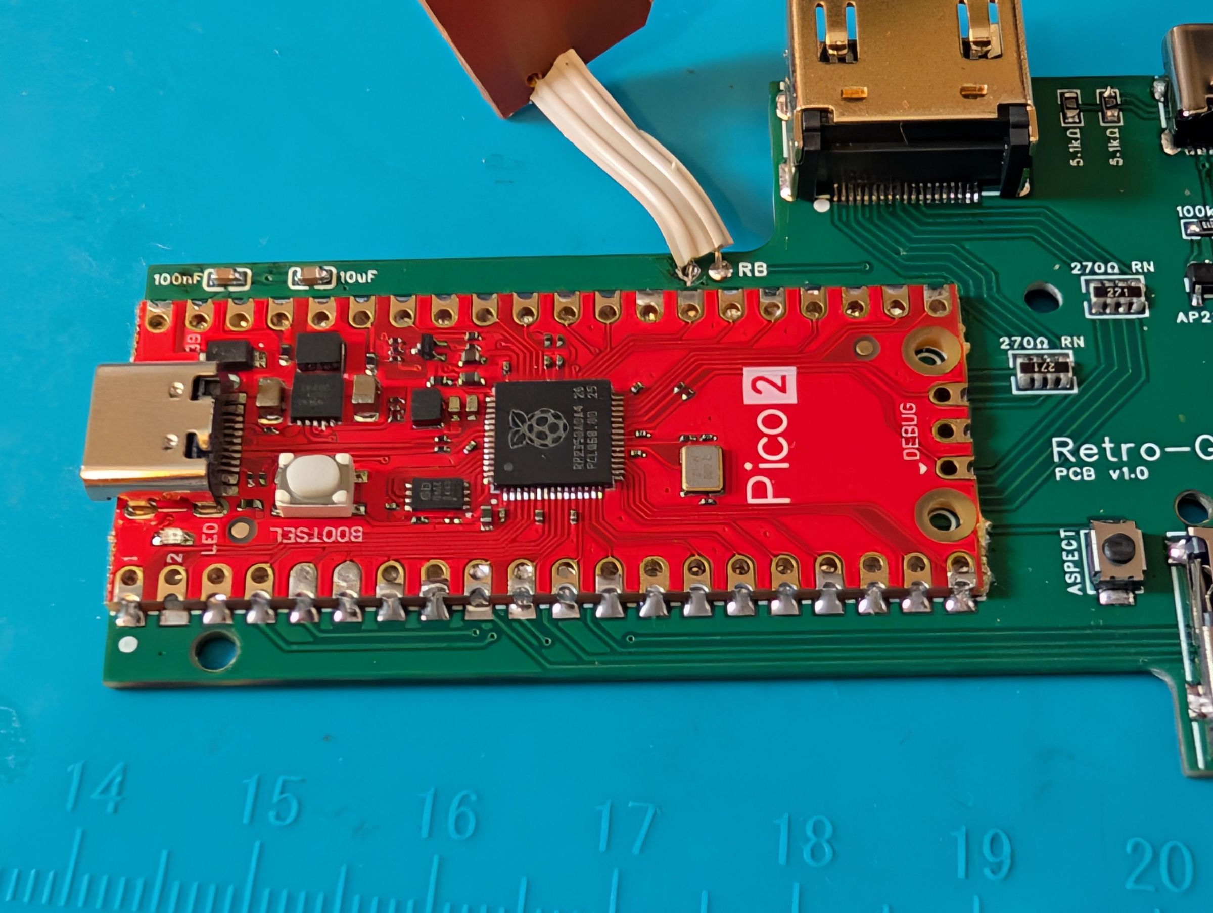
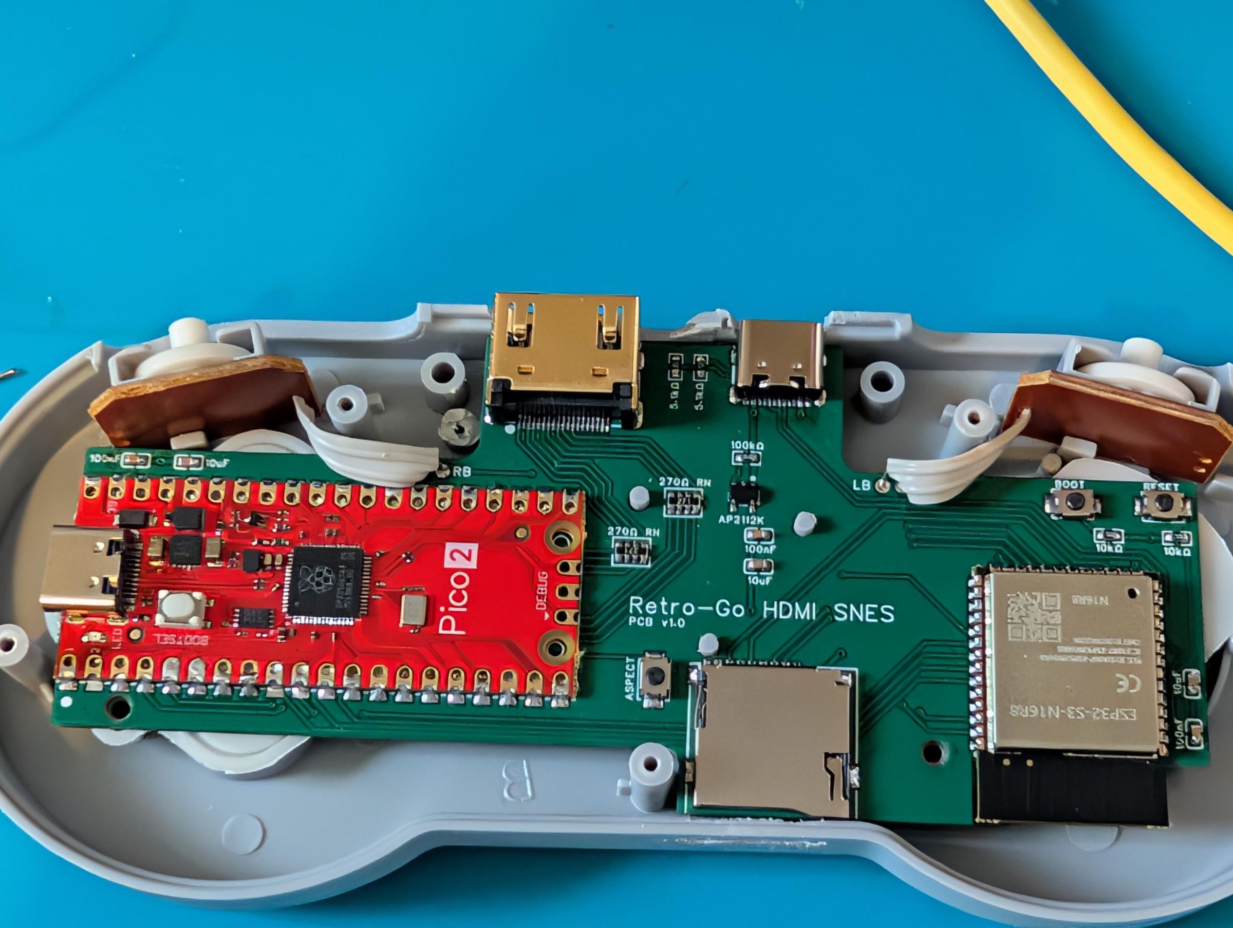
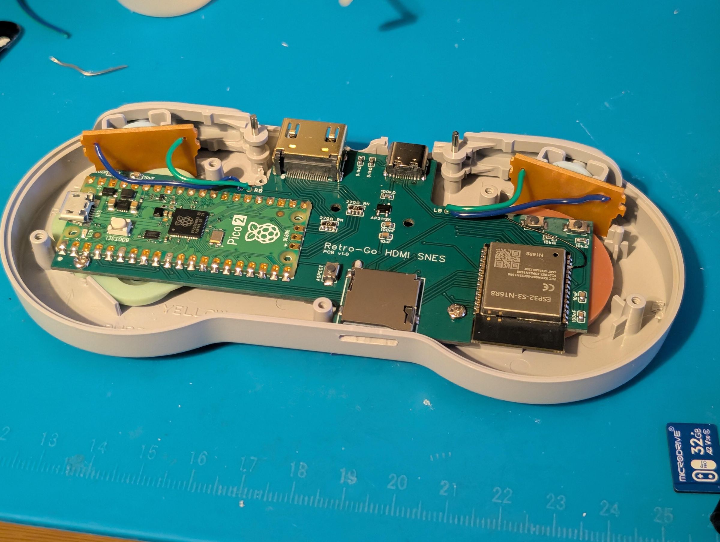
I would recommend starting off doing the 2x 270 Ohm resistor arrays first, these can be fiddly and you want as much access as possible. I usually start by applying a little solder to one pad, heating the pad and then sliding in the resistor array until its lined up, then put a little solder on the opposite side, after that use plenty of flux to ensure all the other pads are soldered and not bridged, a multi-meter helps to confirm theres no bridges.
Then I did the HDMI port since that was also not that easy due to the small pins, use flux (careful not to get it into the actual port) I recommend soldering one of the ground legs on the underside first and checking that the port is lined up and even, then once its set, solder the remaining ground/anchor holes and ensure theres no bridged pins but also that each pin is soldered, not bridged and solid.
After that do the USB-C port, very similar to the HDMI, one ground pin first so its lined up, do remaining ground/anchor holes and small pins so use flux so ensure the pins are soldered, solid and not bridged.
On both HDMI and USBC, the anchor holes are very important else the port will likely come loose, so ensure that the solder is fully flooded through both sides of the board. If its just a small blob on the bottom side creating a shallow 'case' around the legs it wont hold solid enough long term. These are also ground points so can suck up a lot of heat therefore you may need a bigger tip and/or more temperature.
Made a mistake with any of these three? Dont worry, you probably got 5 PCB's when you ordered and plenty of HDMI & USBC ports, so just have another go on another board. It honestly gets easier the more you do, so you'll likely fly through the second time!
The ESP32-S3 needs to be pretty well lined up since it has pins on 3 sides, so if one side is off it'll carry on its way around the whole thing, so make sure you double check. Similar to the resistor arrays, I tin one pad first and then bring in the ESP32 to line it but, make sure all 3 sides to well placed before soldering in another side to secure it in, then work your way around the chip. Check for shorts!
If you've successfully done the above, then its likely clear sailing after this, so its kinda up to you after that, you can probably tell the rough order by the pictures. I try to solder the things with the limited access first to make my life easier.
You will need to desolder the L&R PCB's from the controllers PCB. The original and aftermarket ones do differ slightly, this projects PCB caters more for the aftermarket but an original ones will work and fit perfectly fine, however the wires may need to be replaced or extended. Theres no orientation/polarity so dont worry about which cable goes where.
Cutting the Shell
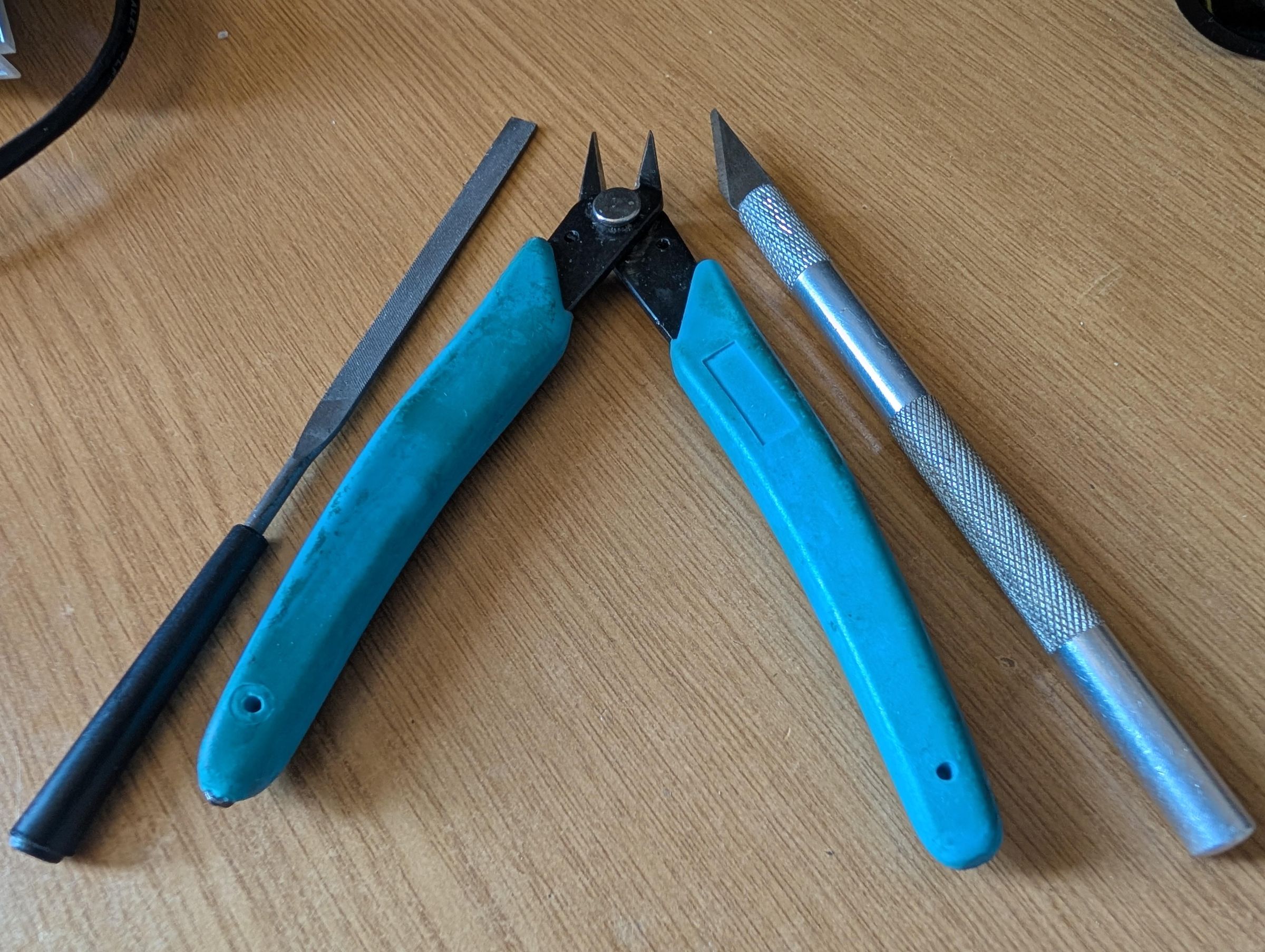
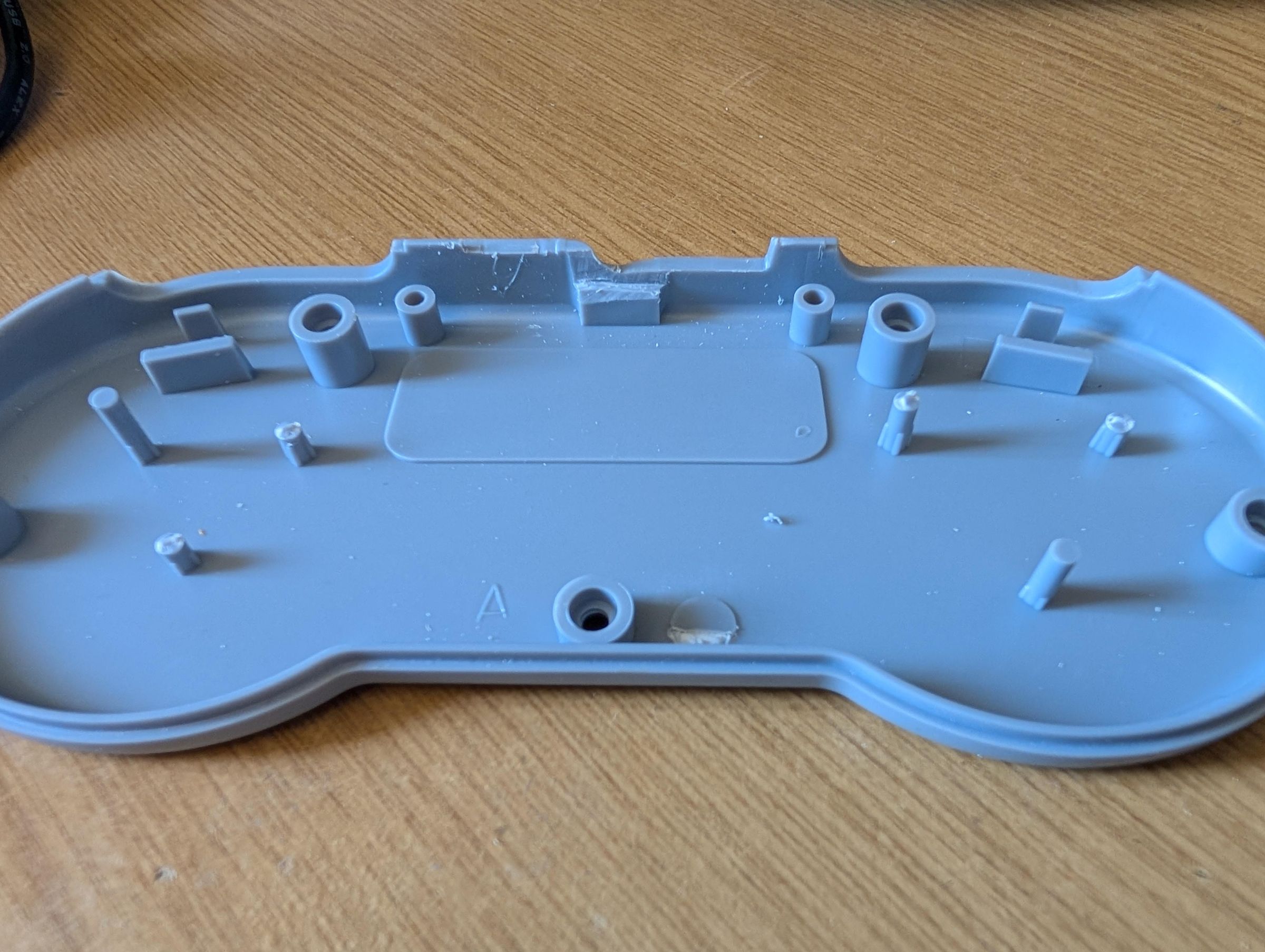
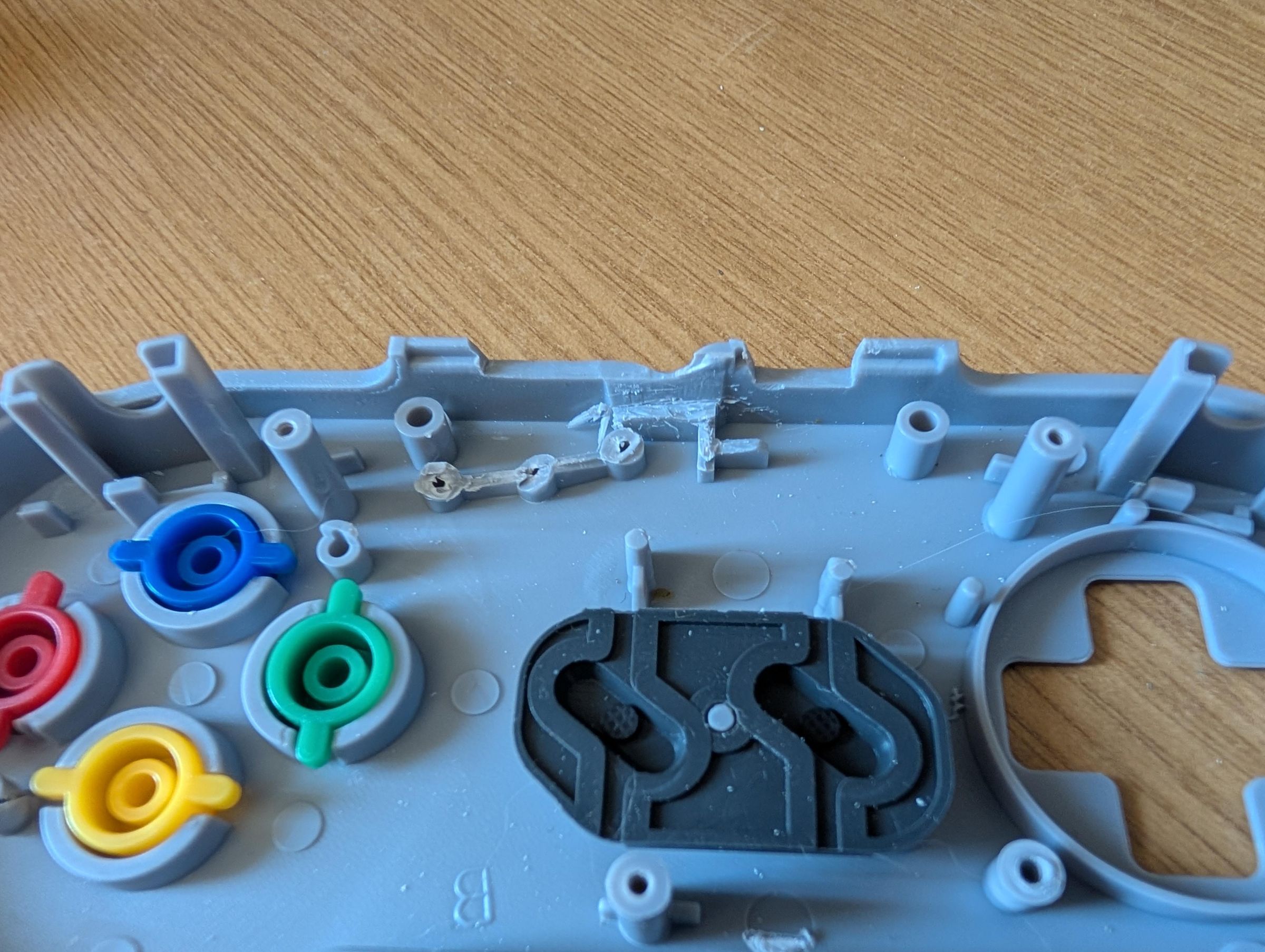
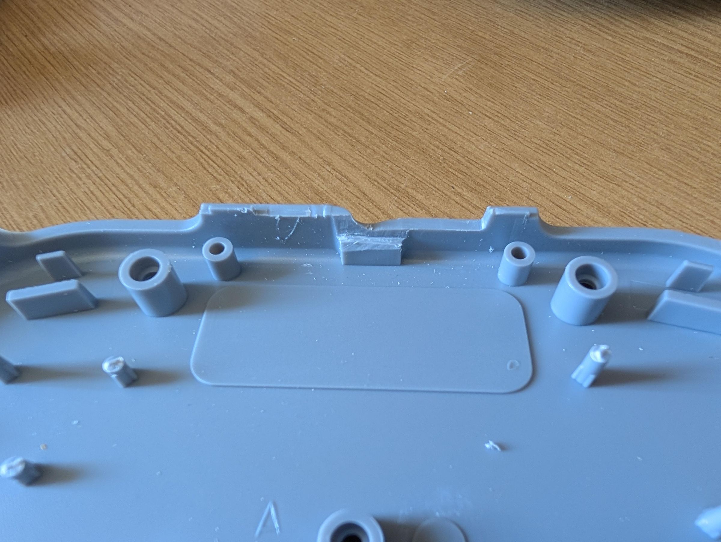
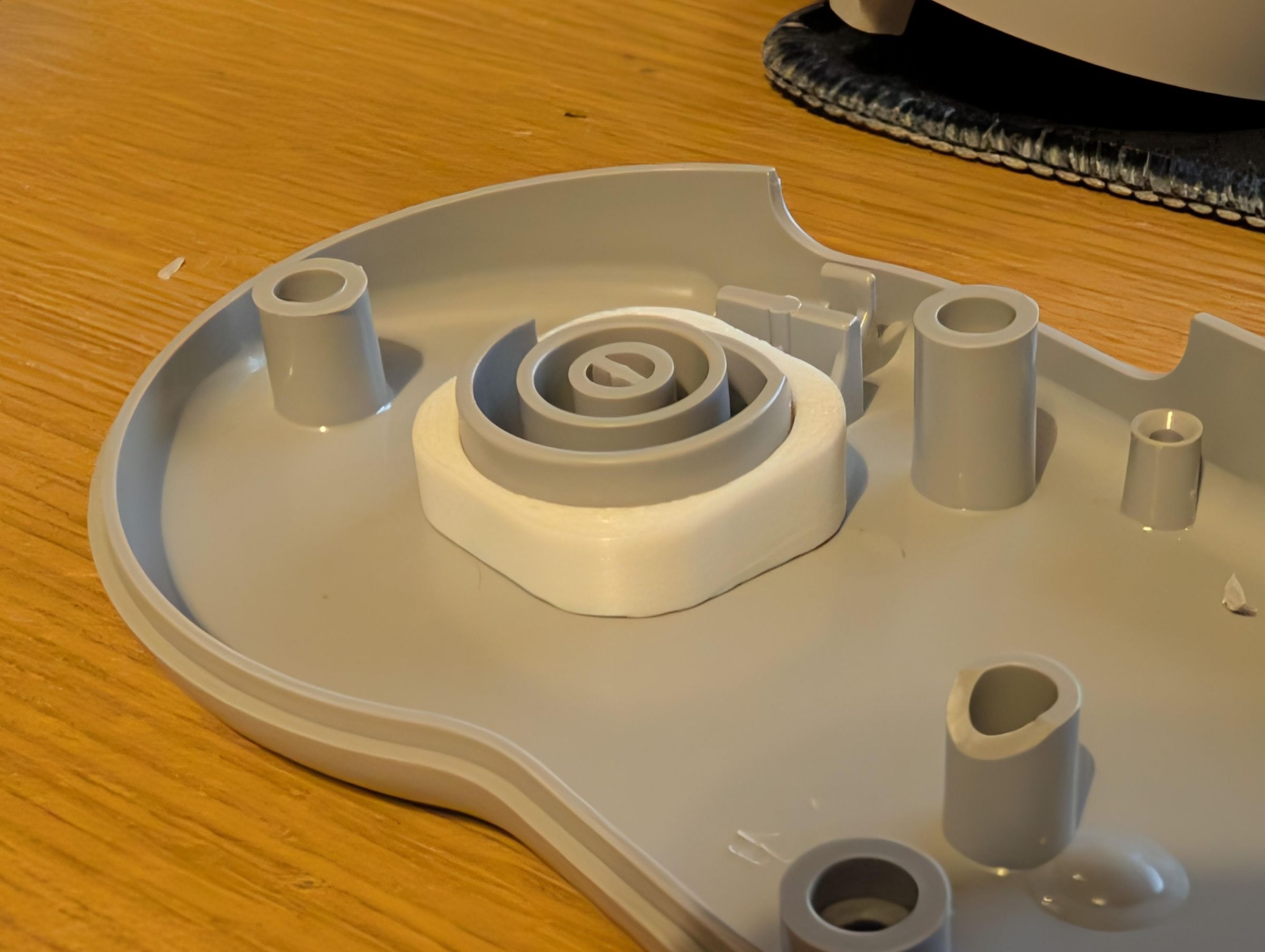
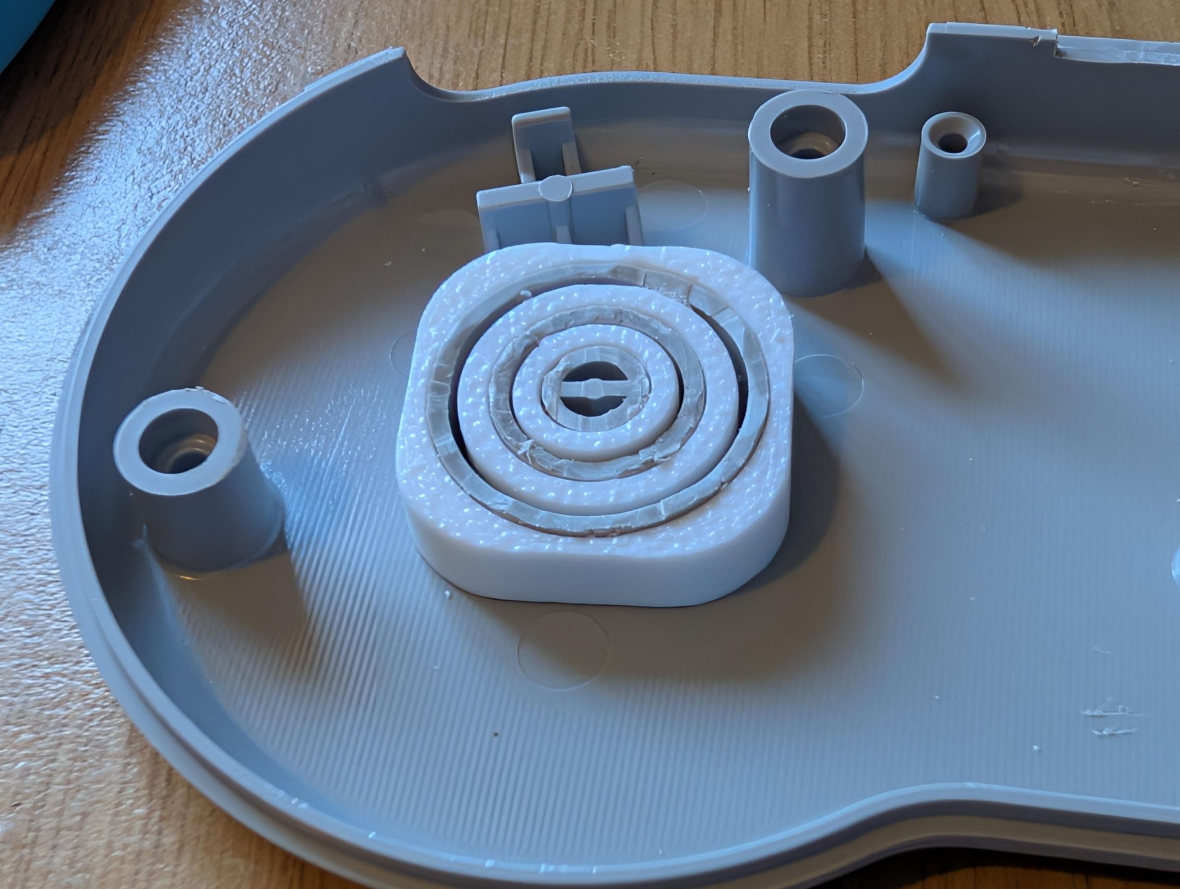
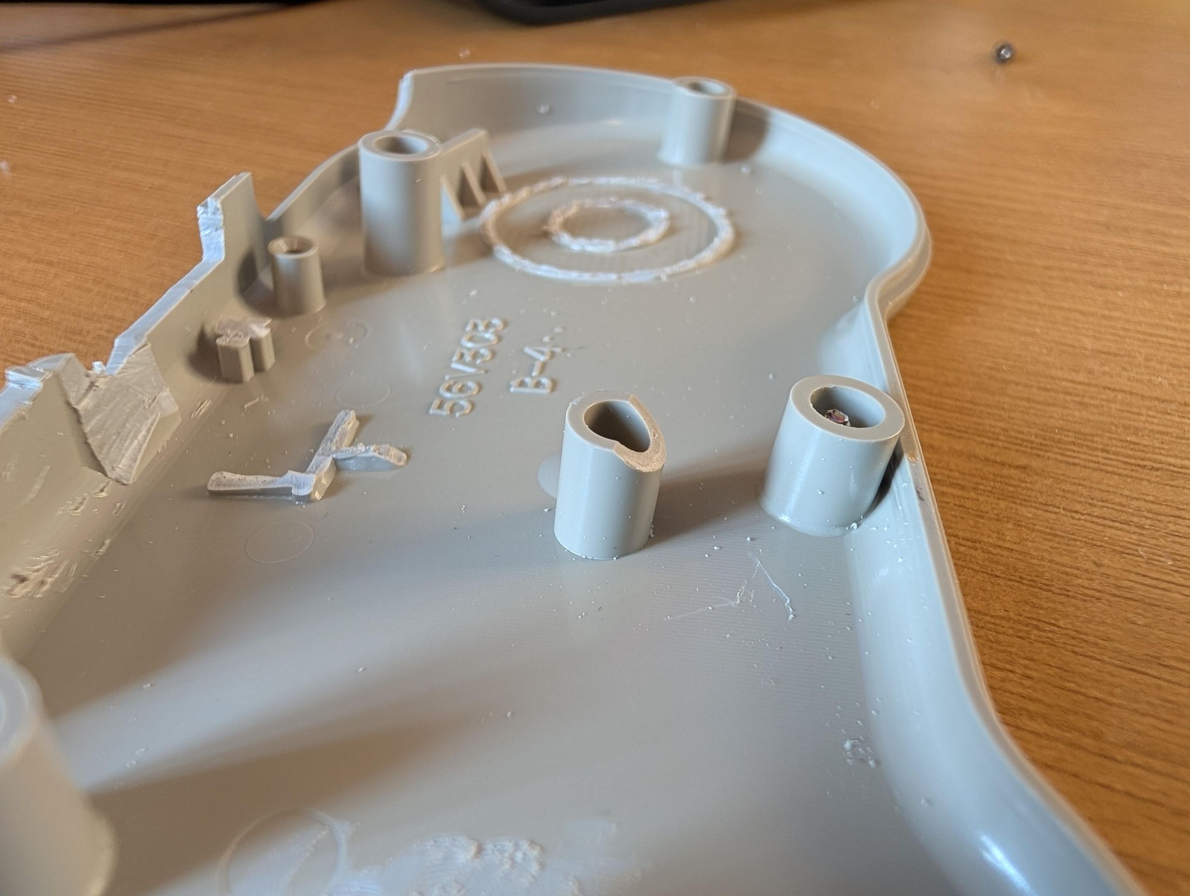
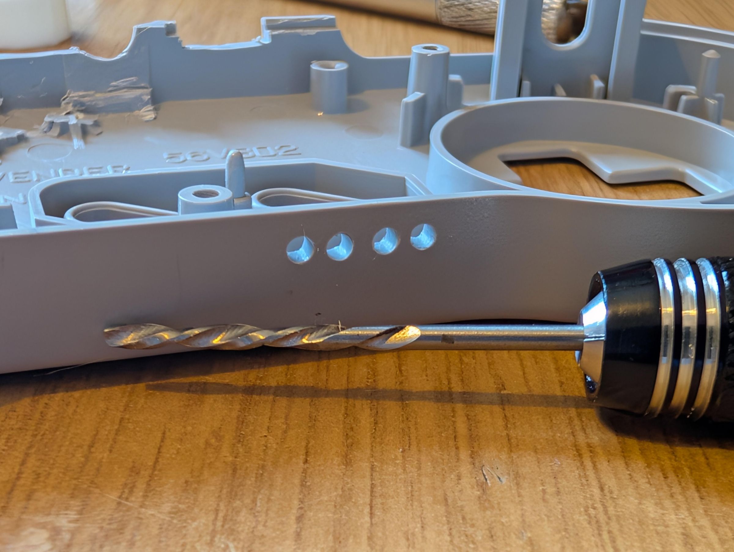
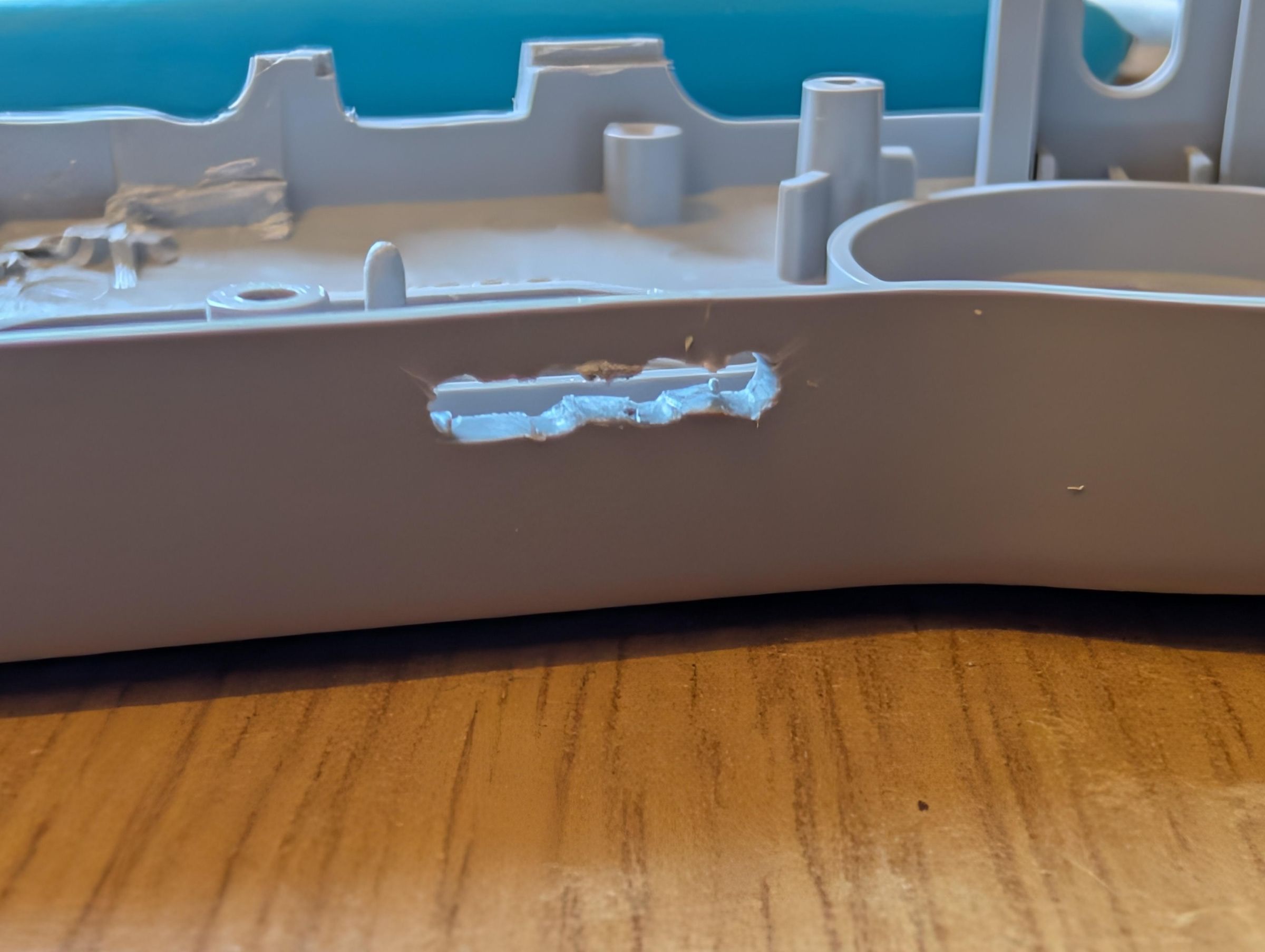
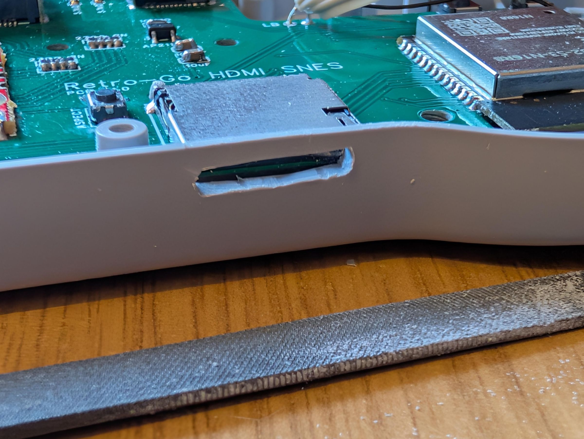
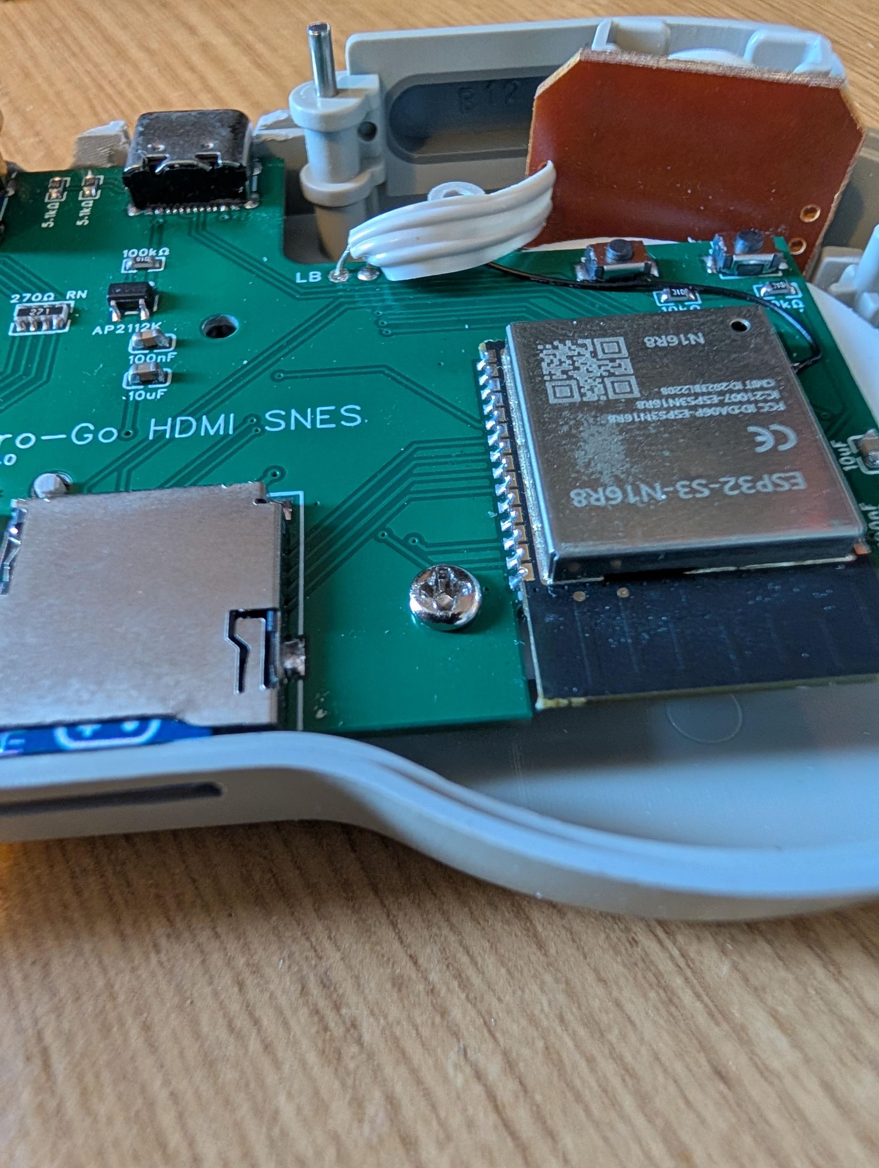
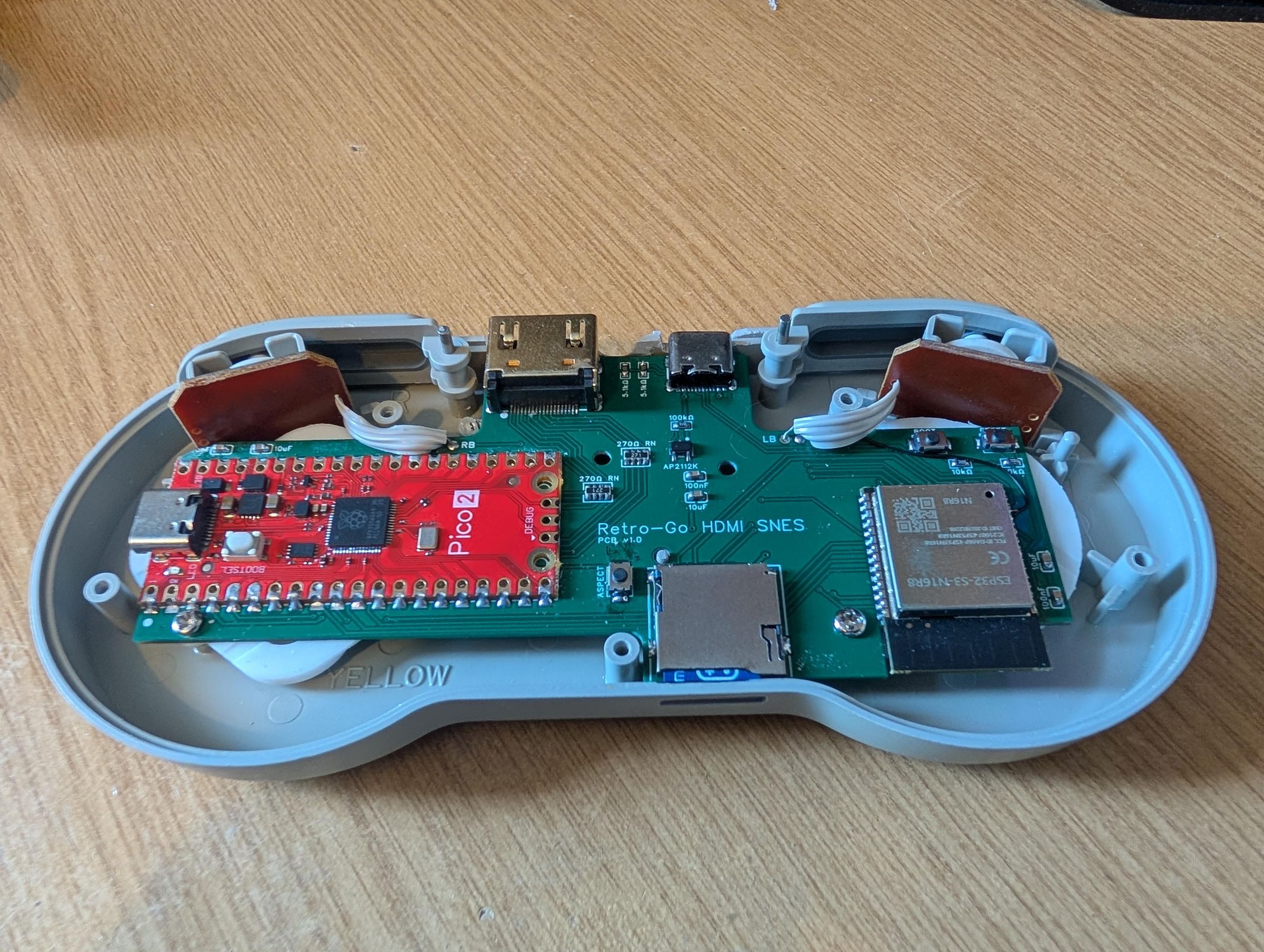
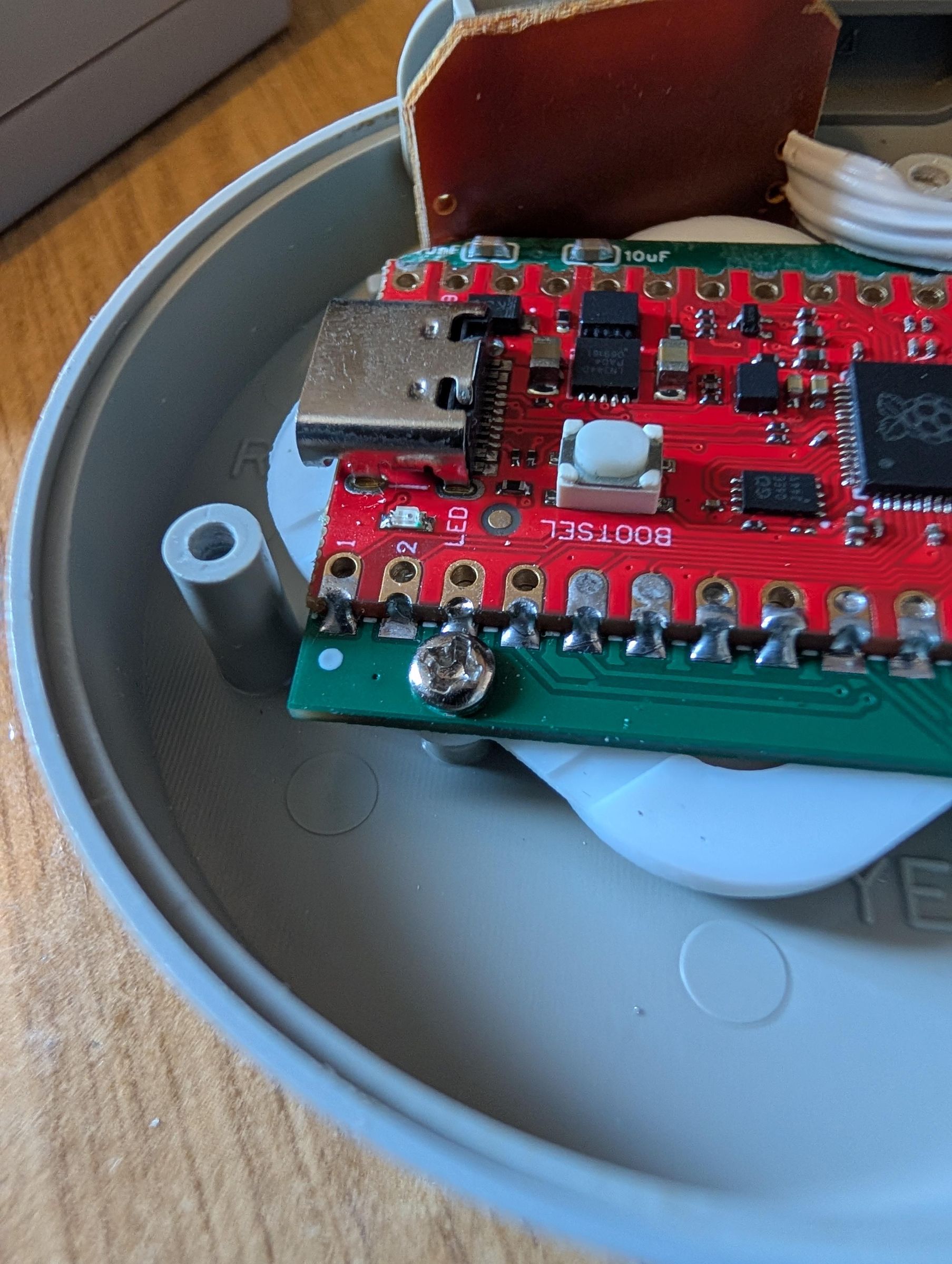
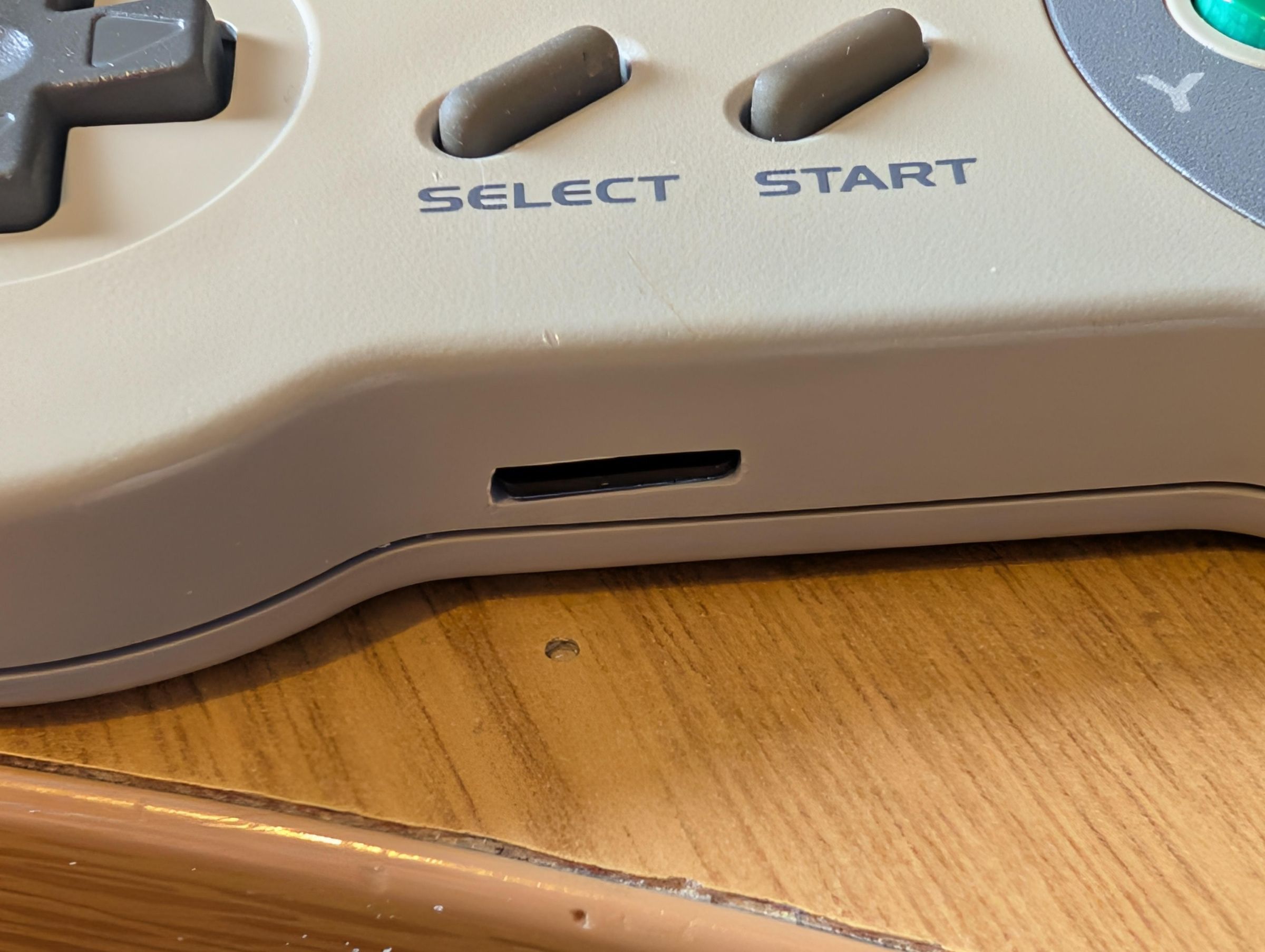
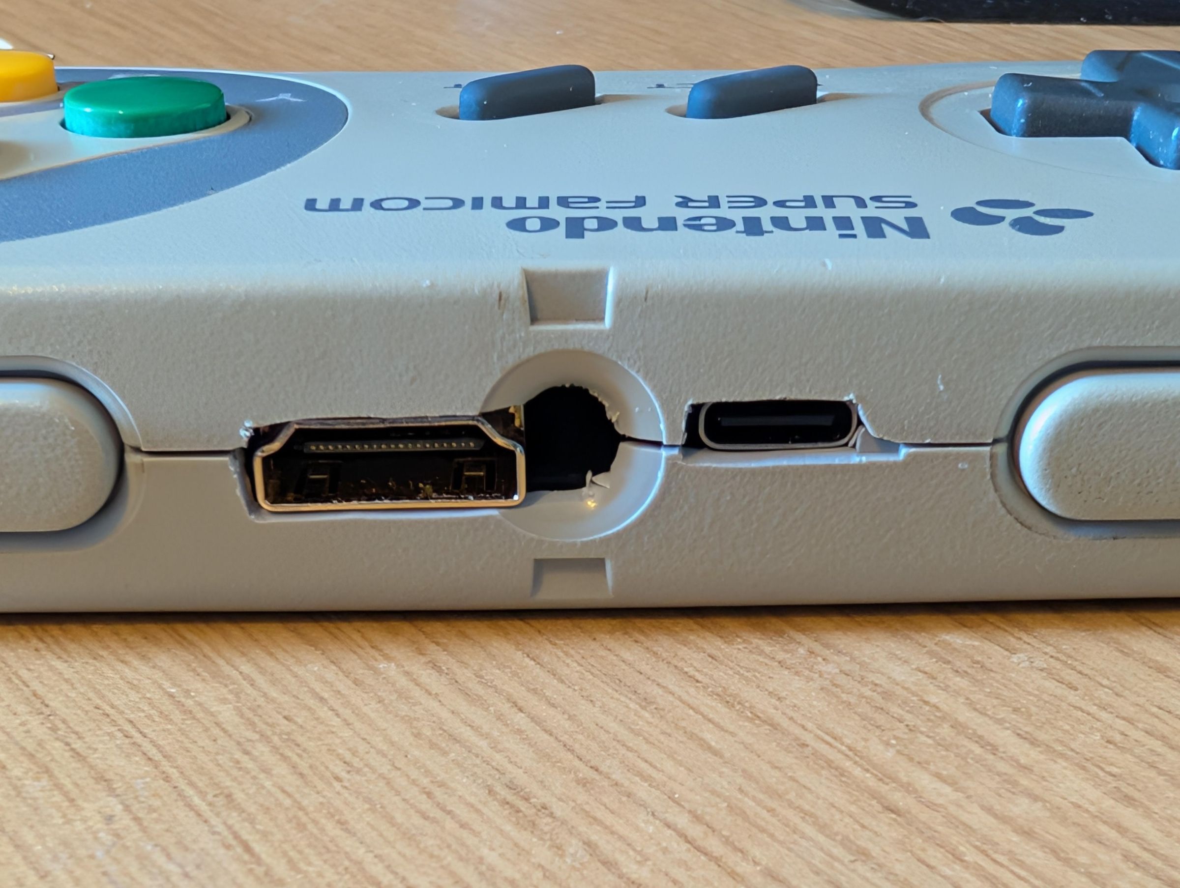
You can use an aftermarket or an original SNES controller. Both shells are actually quite similar and most of the heavy cutting is done up the top around cable area.
I used 4 tools: a hobby knife, a small file, a 1.2mm drill bit (hand drill) and some side cutters. However a multitool with various grinding/sanding attachments will also make light work.
I used the side cutters to remove the bulk of the posts etc. I used the hobby knife to remove most of the material around the HDMI and USB ports, it found it worked very well to slice through the plastic in small layers and it felt left clean cuts. Obviously be careful with the knife, its easy to cut yourself if you slip. If you're unsure, then its safer to use a multitool.
The MicroSD slot was maybe the hardest to look good as it needs a hole to be made in the middle of the case. For this I used a 1.5mm (or similar) hand drill to drill some holes along the line where the SD slot would be, I used the hobby knife to make the 4-5 small holes one slot, then I used the file to extend the slot in whatever direction was needed!
You may also notice that you need to cut away quite a bit of the backshell, esp the parts that help support the DPad and action buttons, theres now a ESP32 and Pico in its way! With the aftermarket shell you can actually leave a few posts (see pics) but the original shell it has a lot of circles, the action buttons are ok to cut away as its supported by a screw and the PCB is stronger due to the Pico but the DPad needs additional support, so see the 3D printed jig to allow you to trim away enough material so it sits on top of the ESP32 and provides good support. I did the bigger ring first and then the inner ones. You also need to use additional screws to secure the PCB: the original controller needs a M2 and M2.6, but the aftermarket is just 2x M2.6, checkout the pictures.
Theres also an aspect button, this allows you to change between stretched/wide screen and normal 4:3. The default is 4:3 but if you're a monster, and want it stretched, the option is there. You can drill a small hole to allow access if you want to change it, or just set it once and dont drill a hole. It can be quite hard to get lined up.
Note the pic showing the 45degree cut on the middle PCB support, this is needed so it clears the SD slot.
This is certainly a job that requires patience and slow work, I highly recommend slowly cutting away material, checking for fitment etc
Downloads
Flashing the Pico and ESP32-S3
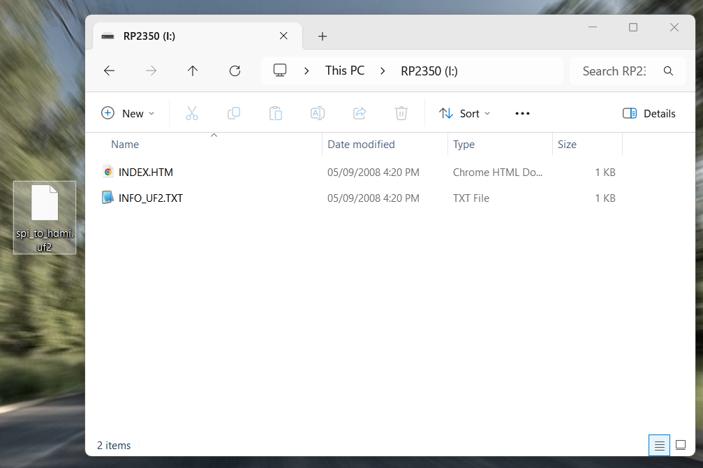
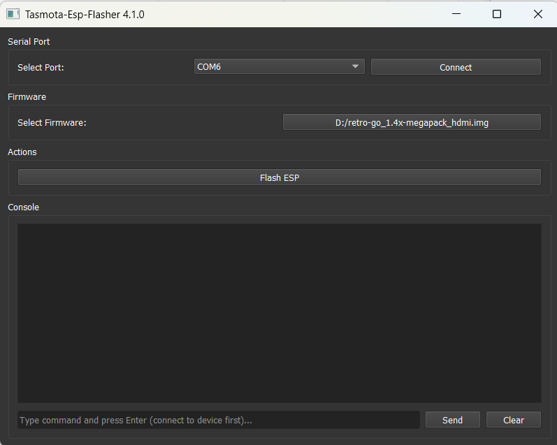
You will need to flash them separately, the USB-C on the actual PCB is the port to flash the ESP32-S3 and the USB-C (or MicroUSB if you have an original Pico2) port connected to the RP2350 is used to flash the Pico.
It should be a one time deal unless new firmware updates are released. You will be able to flash the ESP32-S3 when the case is closed but flashing the Pico will require the case to be opened so I recommend flashing the Pico before you put it into the shell, just hold the BOOT button on the Pico while plugging in the USB cable, it will show up as a flash drive your on your PC, download the firmware HERE and drag it into the drive. The drive will disconnect when the flash has completed, this is normal. Theres no other indication on the Pico or device, so dont worry at this stage.
You can also flash the ESP32-S3 before you put it into the shell if you want. This can usually be done by simply plugging in the USB cable on the PCB, it should pick it up as a COM port. For flashing the ESP32, I recommend ESP-Flasher grab the Retro-Go HDMI image (retro-go_1.4x-megapack_hdmi.img) from HERE, download somewhere, point ESP-Flasher to it and click 'Flash ESP' It should flash.
If it doesnt flash and gives an error, then sometimes ESP32's come with a test flash installed already, if you have an issue, unplug and this time hold down the 'BOOT' button the PCB (not the one of the Pico) while plugging in the USB, it may pickup a different COM port this time and try again.
Once both have been successfully flashed, you can test by plugging in the HDMI and power, you should see a display. May give an error about needing an SD card so continue to step 4.
If you get no display, you will need to do some fault finding. Check for any bridges or poor solder joints, reflash the firmwares, check for any shorts to ground on the power rails.
Setting Up the SD & Usage
Retro-Go has all the emulators and ports built into the flash but requires an SD card with your roms & port data, which you will need to supply yourself, however below is a SD structure pack that helps get all the folder structure setup, plus it has a different theme and some shareware files for Doom, Quake and Duke3D.
Download the SD pack HERE
Copy it to a FAT32 formatted SD card. You can then add your games & port data files.
The rom files can be zipped or unzipped, however the romart only works if the files are unzipped (as it relies on reading the files CRC32). Just copy them to the correct directory e.g. Gameboy games go in roms/gb, NES into roms/nes etc
As for the ports, you will need to obtain the relevant data files. Some games like Duke/Doom for instance are just single files, however other games like Wolf3d or Tomb Raider etc require multiple files.
Theres information on some of the ports that require additional data files that are more than just a single file:
Cannonball, OpenLara, Wolf3D, Rise of the Triad
Note that especially for OpenLara, it requires additional conversion so follow the readme.
NOTE: To access the menu system, both in game and in the menu, you need to press both START & SELECT together. You can then access the other various options such as save states, exit etc.
Power by HDMI!
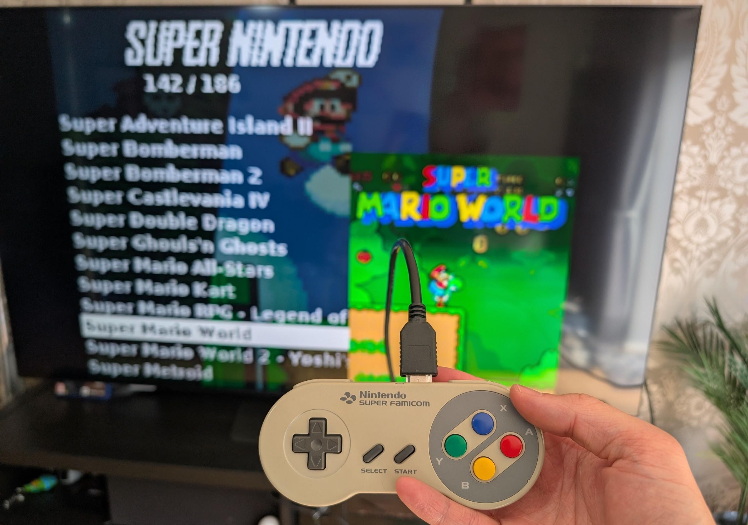
So yes, you can power this device purely from HDMI. It requires a 5v injector, which you plug into the back of your TV and then the USB into a USB port on your TV. It will supply 5v.
Its not harmful to the TV or the device* as its normal for 5v to be supplied via the HDMI but usually very low, this just supplies more amperage. A device only takes the amps it needs so its not dangerous to supply high amps.
*Note! Its potentially harmful (probably mostly to the device) if you use the HDMI v5 injector and also plug in another USB into the device, as this may backfeed some voltage. Please dont plug both in at the same time, theres no protection on this board to protect against any backfeeding but as mentioned this will never be an issue if theres only ever one power source.
Wrap Up
So thats it. You now have a Retro Console inside a SNES controller to play all of your classic games as well as some classic 90's ports.
A few things to remember:
Its running on an ESP32-S3 (240Mhz CPU with half a megabyte on internal memory) so some of the harder to emulate systems like SNES (ironically!), GBA & MegaDrive struggle to get full speed. Overclocking can help (via the Options menu by pressing START+SELECT together) also turning off the sound does get a very big boost in performance.
Obviously the picture quality isnt amazing. Remember we're essentially running at 320x240, upscaling to 640x480 for HDMI and you maybe then plugging that into your 65" 4k TV, the games themselves actually look fine tbh well unless you're used to RetroArch with various highend shaders etc :) The Retro-Go menu looks quite sharp on a 2" handheld display, not so much on a 65" one :)