Reyax RYUW122-Lite Distance Measurement Module – How to Configure, Use, and Measure Range | UWB Tech | Positioning Without GPS | Reyax | AkashWave RF
by akashwave rf in Circuits > Arduino
32 Views, 0 Favorites, 0 Comments
Reyax RYUW122-Lite Distance Measurement Module – How to Configure, Use, and Measure Range | UWB Tech | Positioning Without GPS | Reyax | AkashWave RF
 | Calibration Guide)
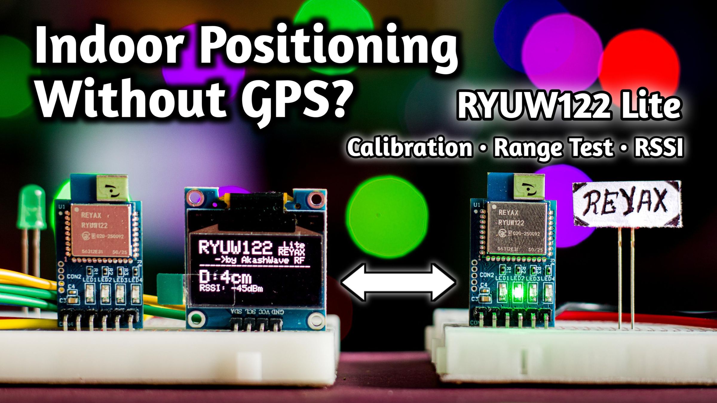
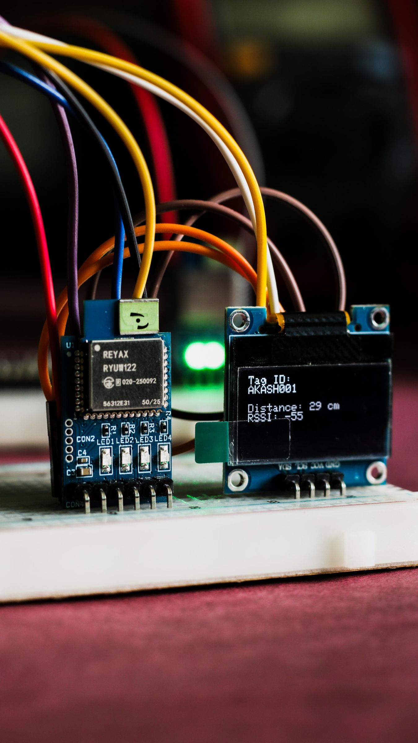
A few days ago, I received a parcel from REYAX Technology containing the RYUW122-Lite module. Unlike traditional LoRa communication modules that are mainly used for long-range data transmission, this module can also send small amounts of data over short distances. However, its main capability is measuring the distance between two nodes using the two-way time-of-flight (ToF) method.
This feature makes the module very useful for applications such as:
• Positioning without GPS (indoor or underground environments)
• Distance measurement between devices
• Robotics and autonomous navigation
• Asset tracking systems
• Wireless sensing networks
In this article, I will explain how this module works, how to configure it using AT commands, and how to calibrate it if you are getting incorrect distance measurements. I will also show how you can use it with microcontrollers like ESP32, or even operate it directly using a USB-to-TTL converter by sending manual AT commands to measure the distance between two nodes.
Finally, I will also show how far these modules can actually work in a real-life range test.
I have also documented the entire project step-by-step in a detailed YouTube video, including the hardware setup, configuration, live demonstration of the module in action, and a real-world range test. You can watch the full video here. 👉 ( https://youtu.be/WTmuCWi43rc )
Now, without any further delay, let’s explore this module.
Supplies
- Reyax RYUW122-Lite UWB Modules – 2 pcs
- USB-to-TTL Converter – 1 pc
- ESP32 Development Board with Programming Cable – 1 pc
- 128×64 OLED Display – 1 pc
- Breadboard and Jumper Wires
- Battery and 3.3V Buck Converter
Quick Explanation
Before diving deep into configuration and coding, let me first tell you how this module actually works in practice.
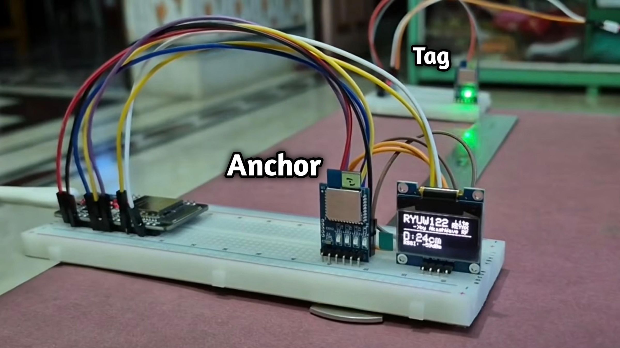
The RYUW122-Lite Ultra-Wideband (UWB) modules measure distance using a two-way time-of-flight method. The Anchor first sends a very precise UWB pulse to the Tag. When the Tag receives this signal, it waits for a known processing delay and then sends a reply back to the Anchor. By measuring the total time taken for the signal to travel to the Tag and return, and subtracting the known delay, the system calculates the signal’s travel time. Since radio waves travel at the speed of light, the module can accurately compute the distance between the Anchor and Tag. The distance information can then be read through the UART interface using AT commands.
In my setup, I used two modules:
- One configured as Anchor
- One configured as Tag
When the modules communicate, the Anchor continuously measures the distance from the Tag, and reports the value through the serial interface.
This allows a microcontroller to read the measured distance and use it in applications like tracking, navigation, or automation.
Configuration & AT Commands
.png)
.png)
The RYUW122-Lite module can be configured using AT commands through any UART interface. To fully understand the module and explore its advanced features, it is recommended to read the complete AT Command Guide provided by the manufacturer.
In this article, I will only show some essential AT commands required for basic configuration.
By sending specific commands through a serial terminal, we can configure:
• Module role (Anchor / Tag)
• Communication parameters
• Operating mode
• Network configuration
• Enable/Disable RSSI
• Output power
& many more
To send AT commands, you can use:
• Arduino Serial Monitor
• USB-to-TTL adapter
• Microcontroller UART interface
Now let’s see the connection between the USB-to-TTL converter and the RYUW122-Lite module for configuration.
USB-to-TTL Converter RYUW122_Lite
3.3V VDD
TX RXD
RX TXD
GND GND
As you can see, this is just a standard UART connection between the two devices.
After completing the wiring, connect the USB-to-TTL converter to your PC and open a serial monitor.
The default UART baud rate of this module is 115200, so configure your serial terminal with the following settings:
• Baud Rate: 115200
• Line Ending: Both NL & CR
Now type the command:
If the module replies with:
then your connection is working properly and you are ready to configure the module using AT commands.
AT Command Setup for Anchor and Tag Modules-
In my long-format YouTube video, I have shown the entire configuration process with a detailed explanation. For a better understanding of the setup and commands, you can also watch the video here: 👉 ( https://youtu.be/WTmuCWi43rc )
Use the following AT commands to configure one module as the Anchor.
________________________________________
Test communication
This command checks whether the module is responding to AT commands.
If the connection is correct, the module will reply with:
________________________________________
Set the module as Anchor
This command sets the module to Anchor mode.
To verify the mode, send:
Expected response:
________________________________________
Set the module address
This command assigns an address ID to the module.
To verify the address, send:
Note:
Each module must have a different address, otherwise the ranging system will not work properly.
________________________________________
Enable RSSI reporting
This command enables RSSI reporting.
To verify the setting, send:
Use the following AT commands to configure another module as the Tag.
________________________________________
Test communication
This command checks whether the module is responding to AT commands.
If the connection is correct, the module will reply with:
________________________________________
Set the module as Tag
This command sets the module to TAG mode. Although the module’s default mode is TAG (0), it is always good to verify it.
To verify the mode, send:
Expected response:
________________________________________
Set the module address
This command assigns an address ID to the module.
To verify the address, send:
Note:
Here I set a different address for the Tag module; otherwise, the ranging system will not work properly.
________________________________________
Enable RSSI reporting
This command enables RSSI reporting.
To verify the setting, send:
Testing Range Using Manual AT Commands
You can also test the distance measurement between two modules using a USB-to-TTL converter and manual AT commands.
First, connect the Anchor module to your PC using the same USB-to-TTL converter, with the same pin connections and serial monitor settings described earlier.
Once the connection is ready, send the following command from the serial monitor:
Here:
• AKASH001 → 8-byte ASCII address of the Tag module
• If the address is incorrect, the Anchor will not receive any response
If the communication is successful, the Anchor will receive a response like this:
Where:
• 80 cm → Distance between the two modules
• −70 → RSSI of the received signal in dBm
This allows you to quickly verify that both modules are communicating correctly and the distance measurement is working properly.
Circuit Explanation

Until now, we were sending AT commands manually and reading the distance and RSSI values directly from the returned responses. However, to use this module in a real project, we need a microcontroller to communicate with it through UART. The microcontroller can automatically send AT commands, read the responses, process the data, and display the results in a more user-friendly way, such as on a serial monitor or a display.
In my setup, I used a microcontroller to:
• Send commands to the module
• Receive distance measurement data
• Process and display the received data
For the Tag module, a microcontroller is not required. You only need to power it using a 3.3V power supply through the VDD and GND pins. The microcontroller is only needed for the Anchor module, which sends commands and reads the responses.
Here, as a microcontroller, I had used an ESP32. The circuit is very simple because the module only requires UART communication and power supply. I also connected an additional GPIO pin D5 from the microcontroller to the module’s NRST (reset) pin so that the module can be reset physically if required.
During my testing, when I used the module with an Arduino Nano, it worked fine without using the reset pin. However, when using it with ESP32 or Raspberry Pi Pico, I needed to trigger the NRST pin once after Serial.begin() in the setup function, otherwise the module did not start properly.
Important points to remember
1. The module operates on 3.3V logic.
2. If you are using a 5V microcontroller, you must use a logic level shifter.
3. A clean, noise-free power supply is recommended for stable operation.
Code
Copy this code and upload it to your ESP32. If the wiring is correct, you should see the received data on the Serial Monitor & OLED Display.
In this line of the code, we are preparing the AT command payload:
Here, AKASH001 is the address of the Tag module. If your Tag module has a different address, you must update the address in this command accordingly.
Calibration
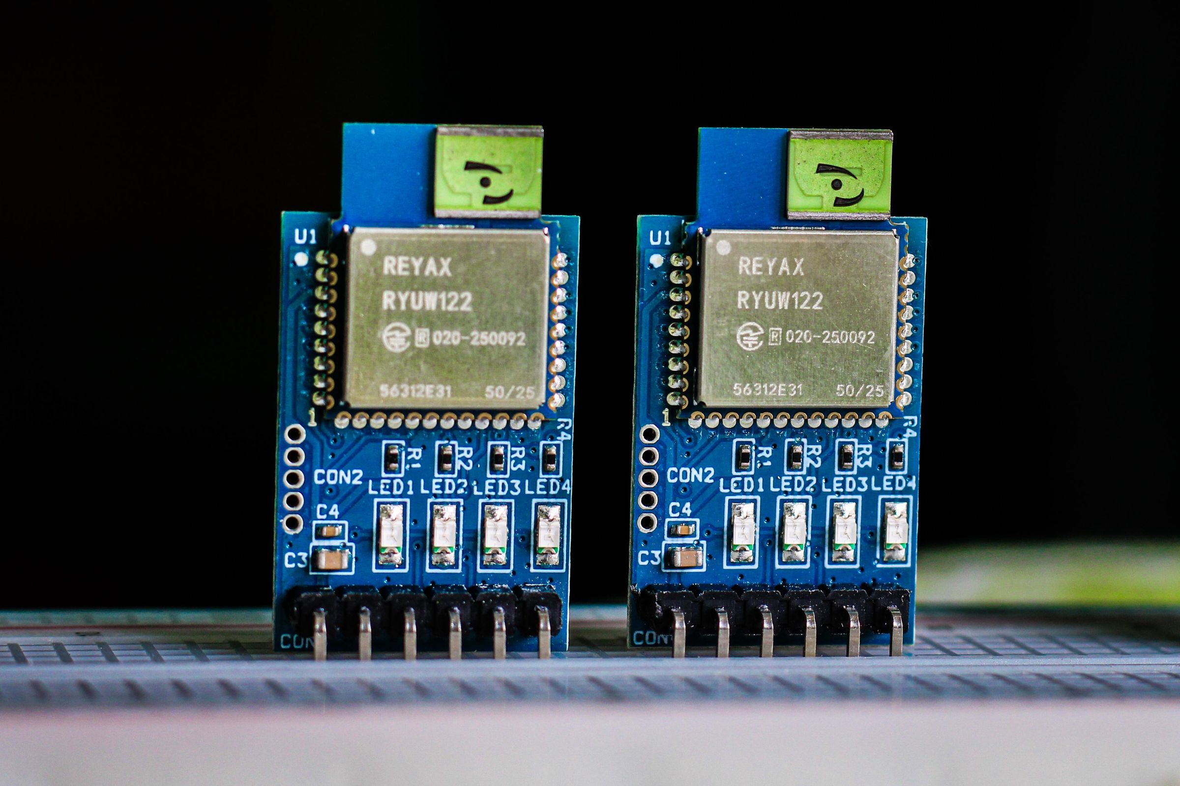
Like many distance-measurement systems, calibration is important for obtaining accurate results.
At first, I placed both modules on the two ends of a 30 cm long scale and observed the distance values reported by the module. Although the measured distance fluctuated slightly, I took the average of several readings, which I also showed in my video.
The average reading reported by the module was 26 cm, while the actual distance was 30 cm. This means the module was measuring about 4 cm less than the real distance, so a +4 cm calibration offset was required.
To perform the calibration, connect the Anchor module to the USB-to-TTL converter again, just like we did during the configuration process. The wiring and serial monitor settings remain exactly the same. After that, send the required AT command for calibration.
This command applies a +4 cm calibration offset to correct the measured distance.
To verify the calibration value, send:
After applying the calibration, the module started reporting around 30 cm, although there were still small fluctuations, which is normal for RF-based measurements.
To verify the calibration further, I placed the modules on the two ends of a 190 cm long table. The Anchor module reported a distance of around 189-190 cm, which is very close to the actual distance.
This confirmed that the calibration was successful and the module was measuring distance quite accurately.
Real-World Range Test
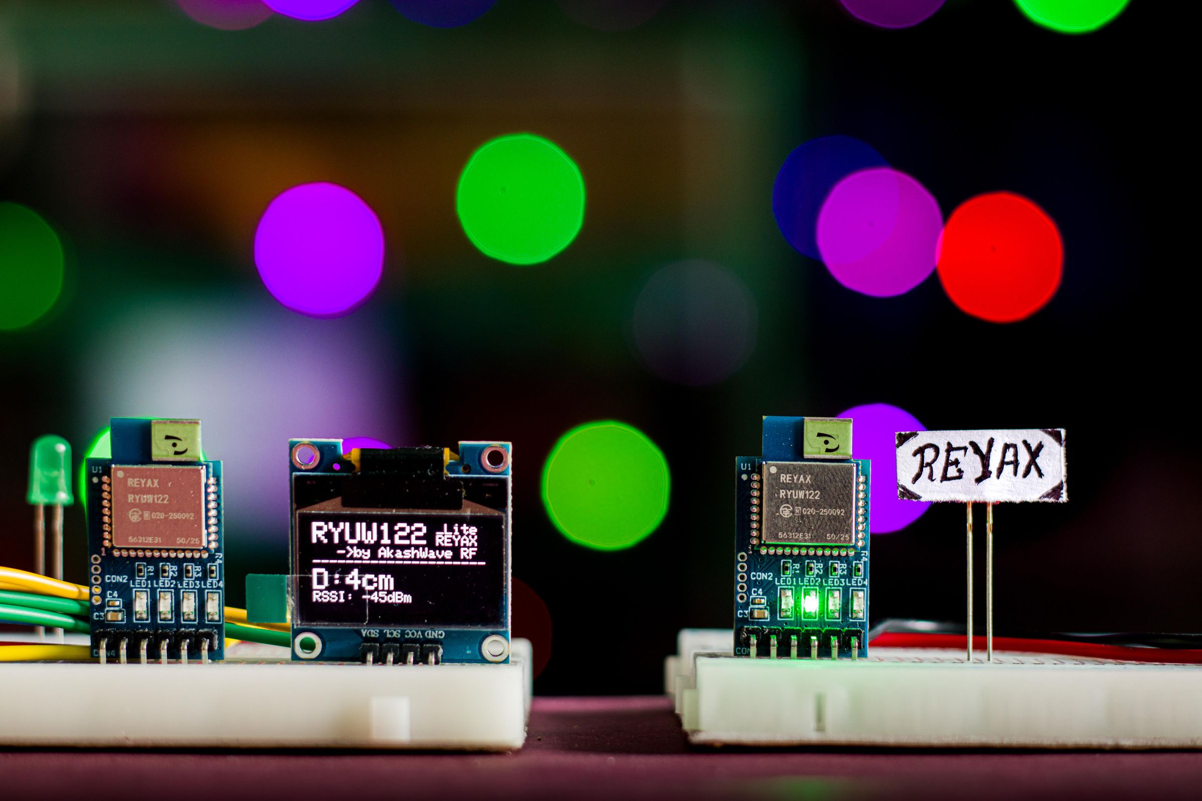
To understand how far the module can perform in real conditions, I conducted a distance test between two modules under clear line-of-sight conditions. Since these modules operate using RF communication, factors such as obstacles, terrain, and antenna orientation can significantly affect their performance.
For this experiment, I placed the Tag module at a fixed location and moved the Anchor module away while continuously measuring the reported distance and RSSI values.
Test Results
• 1000 cm away — RSSI −90 dBm → Working perfectly, no issues
• 3200 cm away — RSSI −93 dBm → Working well, occasional signal loss
• 4500 cm away — RSSI −96 dBm → Working reliably, no major issues
• 6600 cm away — RSSI −100 dBm → Working, but signal loss increased; still usable
• 7300 cm away — Signal lost most of the time; not usable at this distance
These results give a practical idea of the real-world operating range of the module under line-of-sight conditions.
The range test results are provided in this article, but if you want to see the actual field experiment and how the modules performed in real-world conditions, you can watch the detailed video where I documented the entire testing process. Here is the link of the video: 👉 ( https://youtu.be/WTmuCWi43rc )
Conclusion
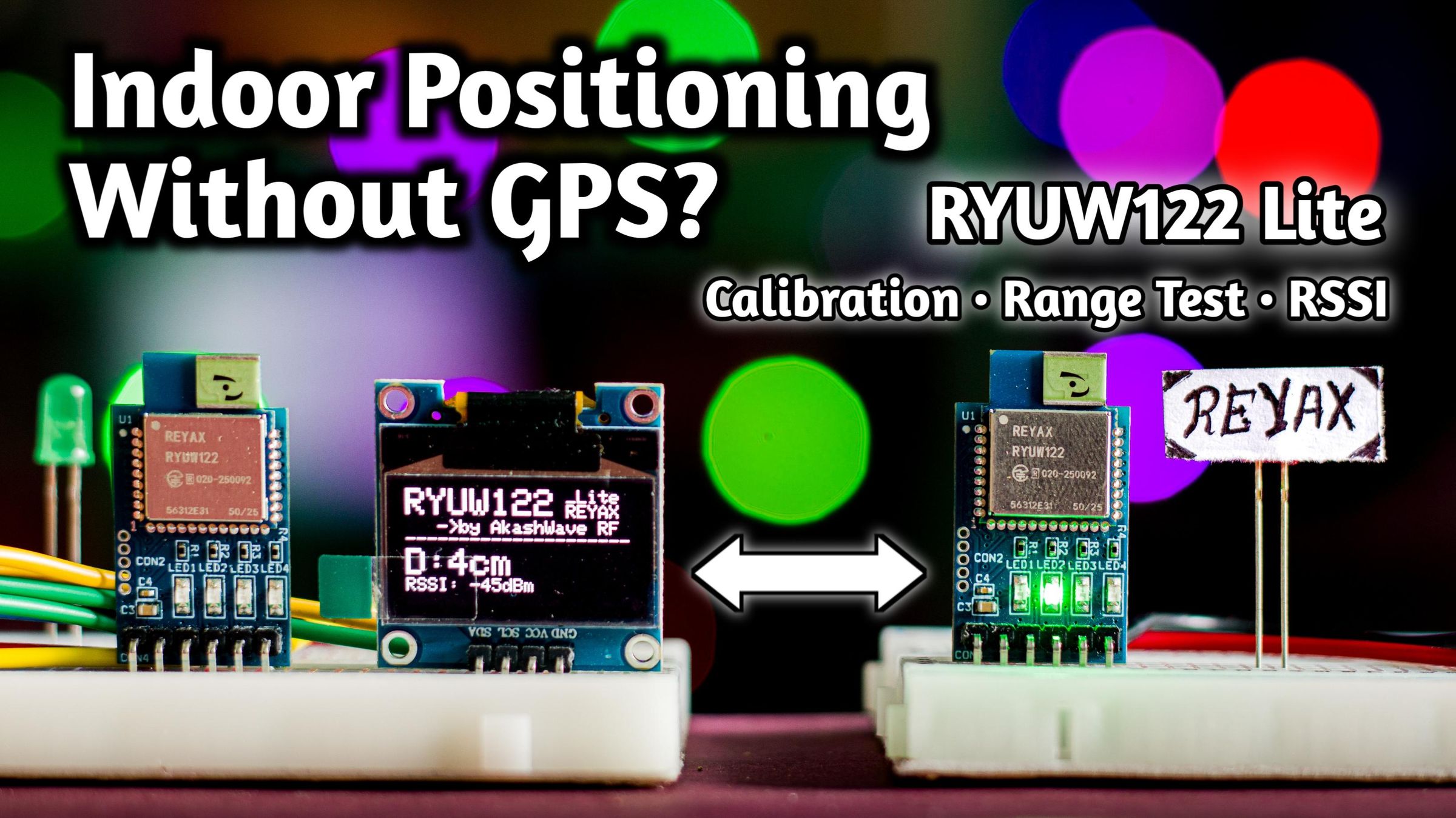
After testing the RYUW122-Lite UWB module in both controlled and real-world conditions, I found it to be a very capable and easy-to-use distance-measurement solution. The module can be configured quickly using simple UART AT commands, which makes it straightforward to integrate with microcontrollers such as ESP32, Arduino, or Raspberry Pi Pico.
During first time test, the module initially showed a small offset (26 cm measured vs 30 cm actual). After applying a +4 cm calibration, the readings became very accurate. A verification test over a 190 cm distance produced readings around 189–190 cm, which shows that the module can achieve good accuracy after proper calibration.
In the real-world range test, the modules worked reliably up to about 45 m, and were still usable at around 66 m, although packet loss started to increase. Beyond roughly 73 m, the communication became unstable and mostly unusable under the tested conditions. This gives a realistic idea of the practical operating range when using these modules in a simple setup without specialized antennas or optimized environments.
Overall, the RYUW122-Lite is a compact and practical solution for applications such as indoor positioning, robotics, proximity detection, and device-to-device distance measurement. With proper setup and calibration, it can provide reliable short-range distance measurements while remaining very easy to interface with common microcontrollers.
If you want to see the entire setup, configuration process, and the real-world range test experiment, you can watch the full demonstration in the YouTube video included earlier in this article. Here is the link: https://youtu.be/WTmuCWi43rc
Thanks to the Sponsor
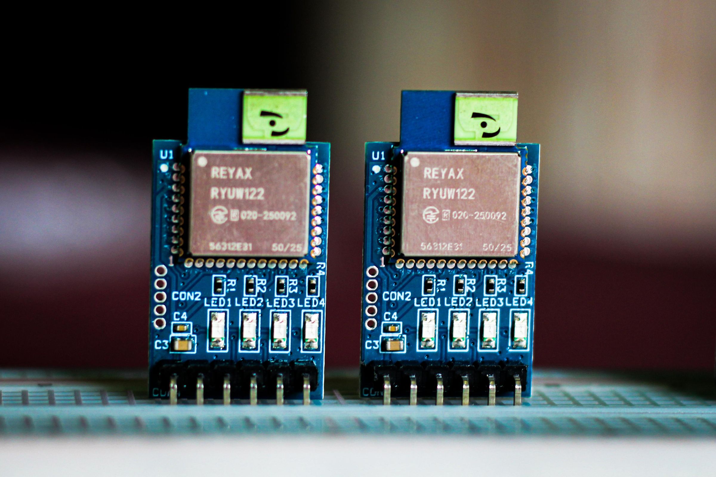
Before continuing further, I would like to thank REYAX Technology for sending me these modules for testing and experimentation.
REYAX develops many useful wireless communication modules including:
- LoRa modules
- UWB modules
- GNSS modules
- BLE modules
These modules are widely used in IoT, wireless communication, and industrial applications.
If you are interested in exploring more products from REYAX, you can check their official website.
🏢 REYAX Official Website:
📦 REYAX RYUW122_Lite Product Page:
➡️ https://reyax.com/products/RYUW122_Lite
All experiments, tests, results, and opinions shown in this video are 100% real, honest, and based on actual field testing.