Robot Triangulation Using Circumcircles
by lingib in Circuits > Arduino
964 Views, 7 Favorites, 0 Comments
Robot Triangulation Using Circumcircles


This Instructable explains how the position of a robot can be determined using three beacons and a rotating laser.
In theory the system is 100% accurate ... in practice the accuracy is within one or two millimetres.
Construction details are provided for each of the following modules:
- 1 only rotating laser
- 3 only beacons
- 1 only Wire-OR combiner
- 1 only beacon setup device (optional)
This project is purely experimental and is published in the hope that some of the ideas may be of use to others.
Images
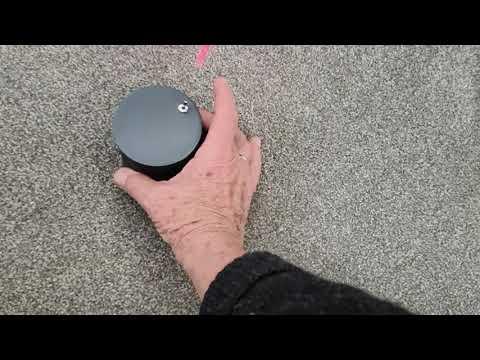
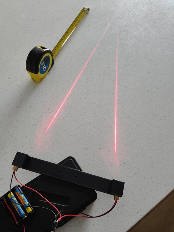
- The cover photo shows an early attempt at detecting the laser beam-angle
- The video shows the system working and how to position the beacons
- Fig.1 shows the problem we are trying to solve.
Caution
This project uses lasers ... avoid direct eye exposure
Supplies


The following parts were obtained from https://www.aliexpress.com/:
- 3 only 650nm light sensors (fig.1)
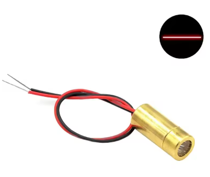
- 3 only 9mm line-lasers (fig.2)
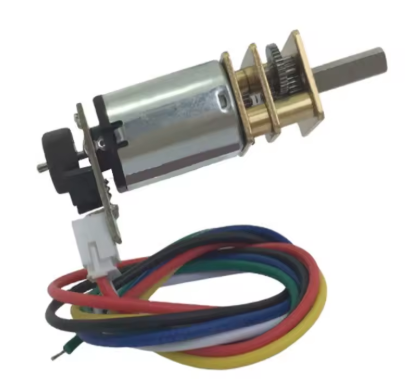
- 1 only High Torque N20 DC 6V 60RPM Gear Motor (fig.3)
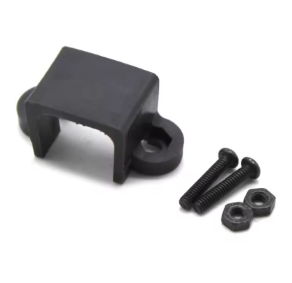
- 1 only N20 Micro Motor Mount. (fig.4)
- 4 only Arduino UNO R3 microcontrollers (fig.5)
The following items were obtained locally:
- 3 only BC547 NPN transistors
- 3 only 33K ohm 0.5 Watt resistors
- 3 only 1K ohm 0.5 Watt resistors
- 1 only 3K3 ohm 0.5 Watt resistors
- 5 only miniature SPDT switches
- 12 only 9mm * 3mm threaded nylon spacers
- 1 only packet M3 x 5mm bolts
- 1 only packet M2 x 8mm bolts
- 3D printed parts described further on.
- hookup wire
The estimated cost of this project is a less than $100.
Suggestion
Overseas postage is expensive. Consider ordering extra components if a supplier offers free shipping over a certain monetary value. This way you get better value for money plus you have spares for your next project.
Concept

A common problem with robots is drift due to wheel slippage and mechanical factors such as backlash. Both lines of text in fig.1 were supposed to be parallel.
This started me thinking ... if the robot confirmed it’s position after each move, then correction factors could be applied prior to the next move. In fig.1 each dot represents a single move.
The method I’ve come up with uses the properties of circumcircles. A circumcircle occurs when two beacons and the robot share the same arc. The mathematics (see later in full) is such that the robot’s current position can be determined if we know the distance between each beacon and are able to measure each of the beacon angles. [1]
Measuring Angles
Angles can be accurately measured if we place a rotating laser beam on the robot and record the time-interval between each beacon response:
- Angle = Time-between-pulses/Time-per-revolution*360 degrees ........................ (1)
At 60 RPM, each revolution takes 1000000 microseconds.
The pin 2 interrupt response time for an Arduino microprocessor is around 8uS. The theoretical resolution is therefore:
- Resolution = 8*0.00036 = 0.00288 degrees or 3/1000 of a degree. ................... (2)
The robot's position can now be calculated since we know the exact distance between each beacon, and each angle to a fraction of a degree.
References
[1]
Inspiration for this project came from this paper which uses the trigonomical relationships of a rectangle to calculate the centre coordinates of a circumcircle:
My method differs in that I use a geometrical method based on the fact that the angle at the centre of a circumcircle is twice the angle at the circumference:
Triangulation Using Angles

This section is highly mathematical and may be skipped.
All you need are formulas (4), (8), (9), (10), (11), (14), (15)
In fig.1 above
Chord1 and chord2 are each 1000mm in length forming an equilateral triangle with the top line which also has a length of 1000mm.
The internal angles of an equilateral triangle are each 60 degrees, which infers that each chord is also at an angle of 60 degrees to the X-axis
Looking at the blue construction lines:
- x1 = r1*sin(B) .............................................. (1)
- y1 = r1*cos(B) ............................................. (2)
Calculating r1
The value for r1 can be calculated using the following formula for circumscribed circles:
- a/sin(A) = b/sin(B) = c/sin(C) = 2*radius ...... (3)
Rearranging and substituting into (3):
- r1 = radius = chord1/(2*sin(Q1) ................ (4)
Calculating angle B:
- Angle B = (60-A) .......................................... (5)
To find angle A we use the “angles subtended by the same arc” theorem which states that “the inscribed angle at the centre is twice the angle at the circumference”. [1]
Since angle Q1 is 140 degrees, the inscribed angle at the centre is 2*140 = 280 degrees which means the internal angle at the apex of the larger blue triangle is 360-280 = 80 degrees.
But the internal angles of a triangle always sum to 180 degrees, and since the large blue triangle has two sides of equal length (both r1), then angle A = (180-80)/2 = 50 degrees.
Angle B is therefore 60-50 = 10 degrees.
Expressed as a formula:
- angle B = (60-Q1)+90 .................................. (6)
Check:
- angle B = (60-140)+90 = 10 degrees
Substituting (6) into (1) and applying the formulas shown in fig.1:
- the magnitude of x1 = -r1*sin(60-Q1) ........... (7)
Since x1 is always to the left of the (0,0) coordinate, we need to multiply (7) by negative 1 to get the actual value for x1. Equation (7) becomes:
- x1 = r1*sin(60-Q1) ......................................... (8)
- y1 = r1*cos(60-Q1) .........................................(9)
Similarly
- x2 = -r2*sin(60-Q2) ........................................ (10)
- y2 = r2*cos(60-Q2) ........................................ (11)
(Note: we don’t multiply 10) by -1 since it’s always to the right of the (0,0) coordinate.
Calculating the robot position at coordinate (X,Y)
The coordinates (x1,y1) and (x2,y2) are the centre coordinates for each circumcircle.
A line drawn between these two coordinates bisects the straight-line between the robot and coordinate (0,0).
The bisection coordinates can be found from these standard formulas:
- X/2 = ((x1*y2 – x2*y1)*(y2 – y1))/((y2-y1)^2 + (x1+x2)^2) ................ (12)
- Y/2 = ((x1*y2 – x2*y1)*(x1 – x2))/((y2-y1)^2 + (x1+x2)^2) ................ (13)
Rearranging:
- X = 2*((x1*y2 – x2*y1)*(y2 – y1))/((y2-y1)^2 + (x1+x2)^2) .............. (14)
- Y = 2*((x1*y2 – x2*y1)*(x1 – x2))/((y2-y1)^2 + (x1+x2)^2) .............. (15)
The beacons can be any distance apart. All formulas are valid providing you know the length of chord1 and its angle to the X-axis, and the length of chord2 and its angle to the X-axis.
References
[1]
The Beacons

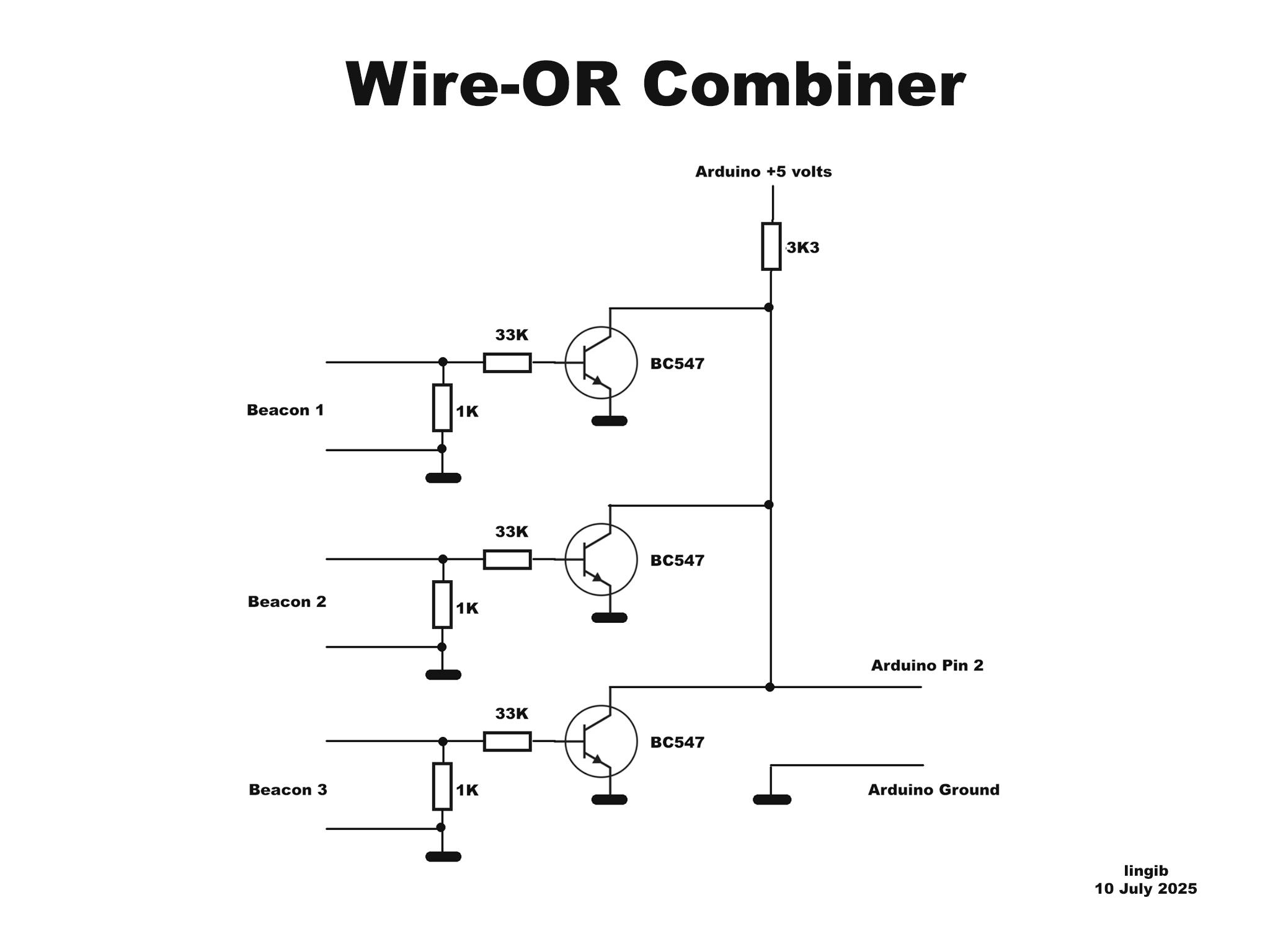
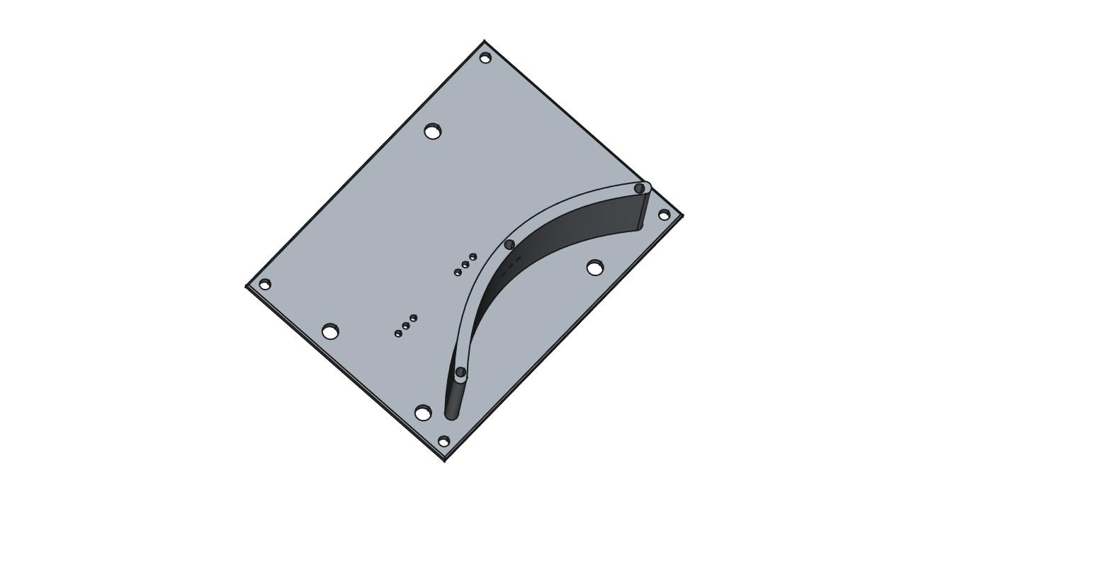
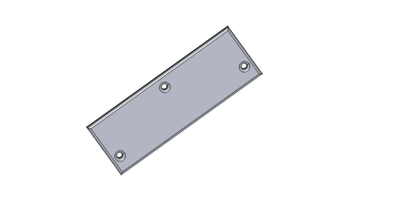
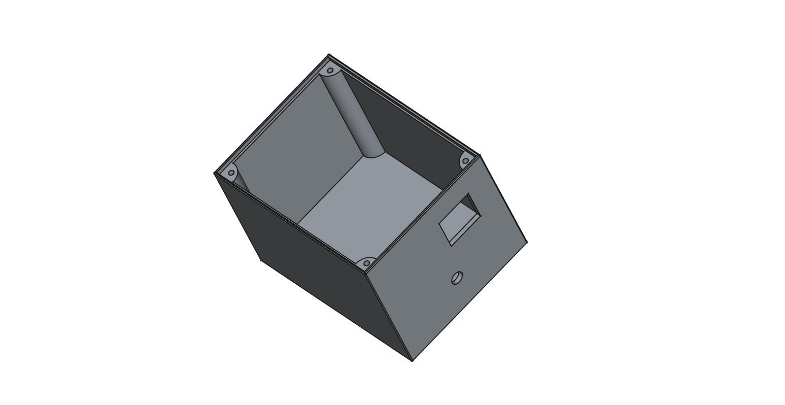
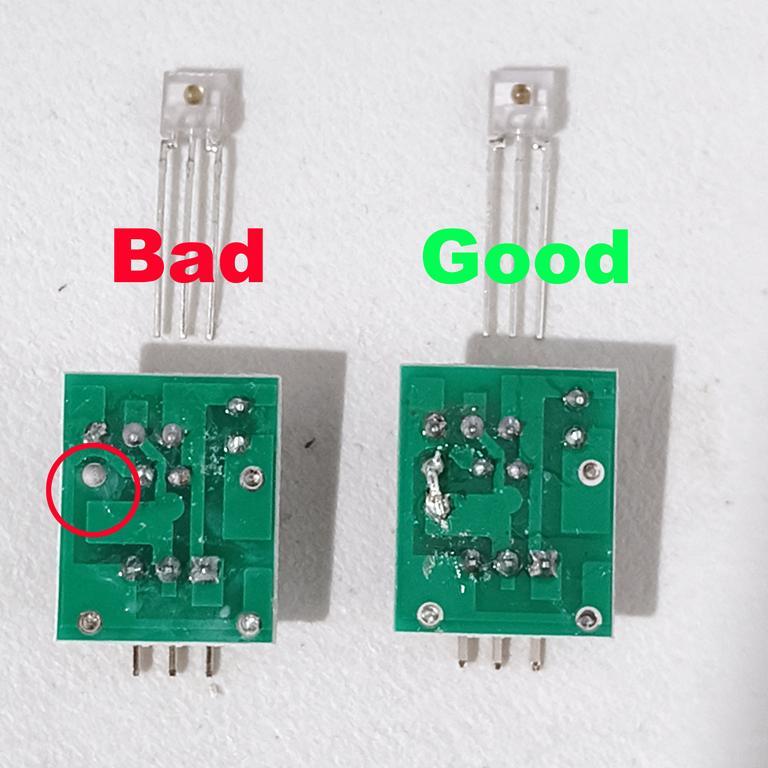
Fig.1 shows the circuit diagram for each of the three beacons.
Fig.2 shows an assembled beacon. The printed circuit for the light sensor is located directly behind the light shield. There are three holes at the rear of the light shield for the light sensor pins. Before inserting the light sensor pins into the printed circuit socket, bend the pins 90 degrees such that the light sensor sits flush with the rear of the shield as shown in fig.2.
The 433MHz transmit module shown in the diagram is not currently used due to unwanted noise spikes at the receiver, but may be at a later date. For now I’ve connected each beacon to a “wire-OR” combiner circuit.
Fig.3 shows the wire-OR combiner circuit.
Fig.4 & fig.5 show the 3D light shield and lid
Fig.6 shows an optional case. This case is not required if you power each from a 5 volt USB adaptor.
Fig.7 shows a light sensor with a faulty printed circuit board
Check your light sensors
Each of the light sensors I received had an unwanted gap in one of the tracks. Unless you “bridge” this gap the light sensor will not work.
Fig.7 shows the necessary modification.
To test your light sensor, plug the sensor into the socket with the dome side facing the pins. Apply 5 volts between Vcc and Ground.
- The data pin should go HIGH when the sensor is covered.
- The data pin should drop LOW when a 650nm laser (or daylight) is shone on the sensor.
The Light Shield
The design of the light shield is such that light can only enter via the front opening.
The shape of the shield is such that any daylight entering the shield at an angle is directed away from the sensor. Only the laser has direct line-of-sight to the sensor.
The light sensor is positioned within the shield such that a laser beam can strike it from anywhere within a 90 degree angle. This allows a +/- 15 degree margin of error when positioning the sensors as the laser only requires a working-angle of 60 degrees.
Beware of sunlight
One morning I found that my system didn’t work. No matter what I did, the light sensor wouldn’t respond to the laser.
After much probing I discovered that the light sensor was permanently triggered. The problem disappeared when I closed the curtains. The culprit ... sunlight.
The light shield is necessary to prevent unwanted sources of 650nm light from triggering the detector.
I found that a small strip of vertically polarised film in front of each sensor helps reduce unwanted light.
The Arduino
The purpose of each Arduino is to:
- match the different logic levels
- set the pulse widths
- generate the required number of pulses
A 9 volt source is not required if you use a 5 volt USB power adaptor and cable to each Arduino.
The Arduino Beacon Software
Download each of the attached INO files:
- beacon_one_pulse.ino
- beacon_two_pulses.ino
Copy the contents of each into a new Arduino sketch using a text editor such as Notepad++ (not a word-processor) and save.
Compile and upload “beacon_one_pulse.ino” into two beacons.
Compile and upload “beacon_two_pulses.ino” into your master beacon (B0)
Light Shield STL Files
The following STL files are for the Light Shield:
- light_shield.stl
- light_shield_lid.stl
- light_shield_battery_cover.stl
The light shield battery cover is not required if you intend powering the beacon from a 5 volt USB power adaptor.
Calibrator
For ease of positioning each beacon, I’ve printed a laser “cross-hair” calibrator.
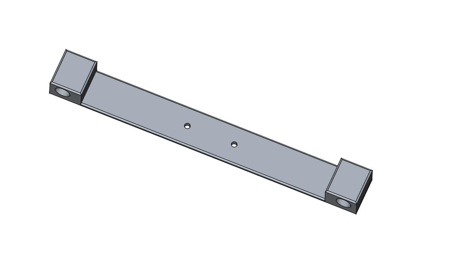
Assembly Instructions
- Fit a 9mm line-lasers into the holes at each end of beam-angle arm.
- Wire each line-laser in parallel (red-to-red, black-to-black)
- Wire two 1.5 volt batteries in series to form 3volts.
- Apply 3 volts to the lasers and orientate the beams so they both produce vertical lines. Avoid direct eye contact ... Do not look into the lasers
- Bolt the laser arm to the direction-plate
Operation
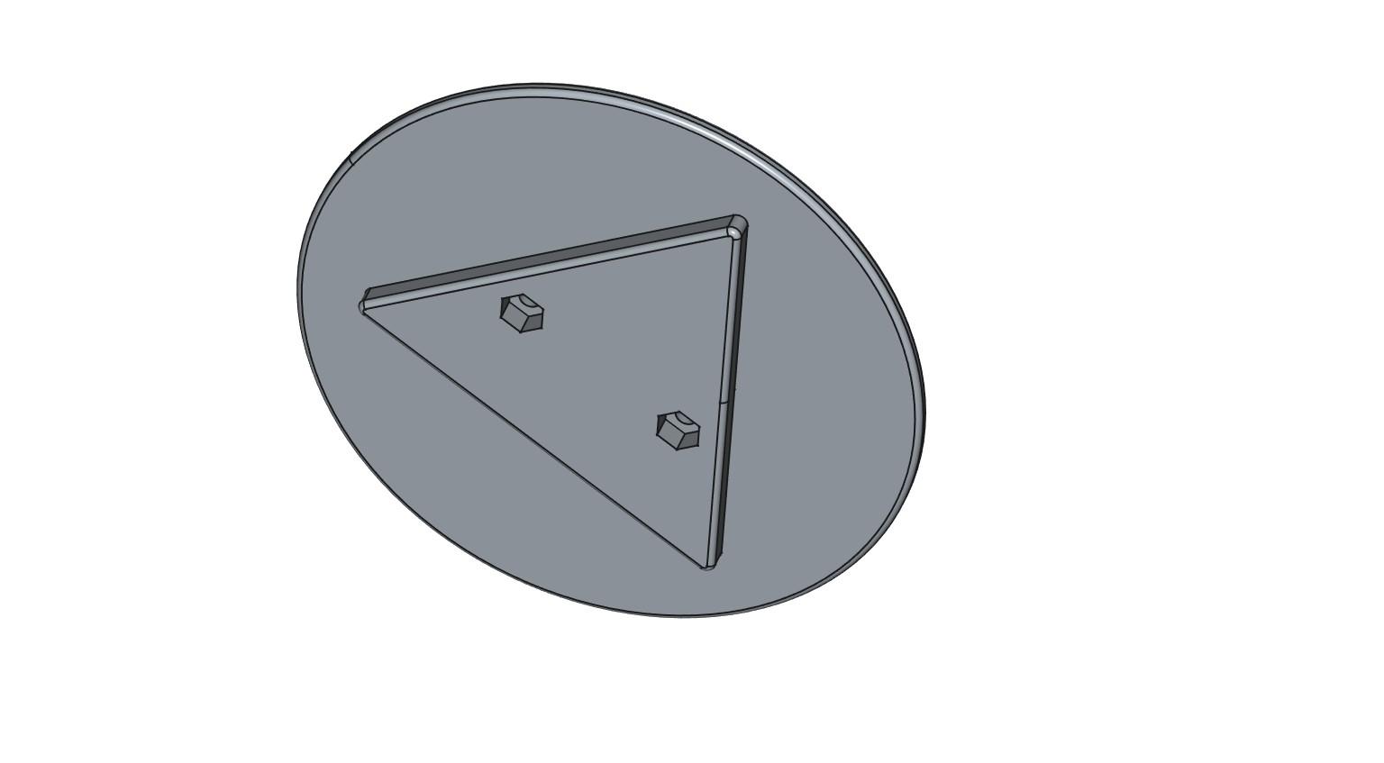
- Tape the base-plate to the floor (to prevent accidental movement)
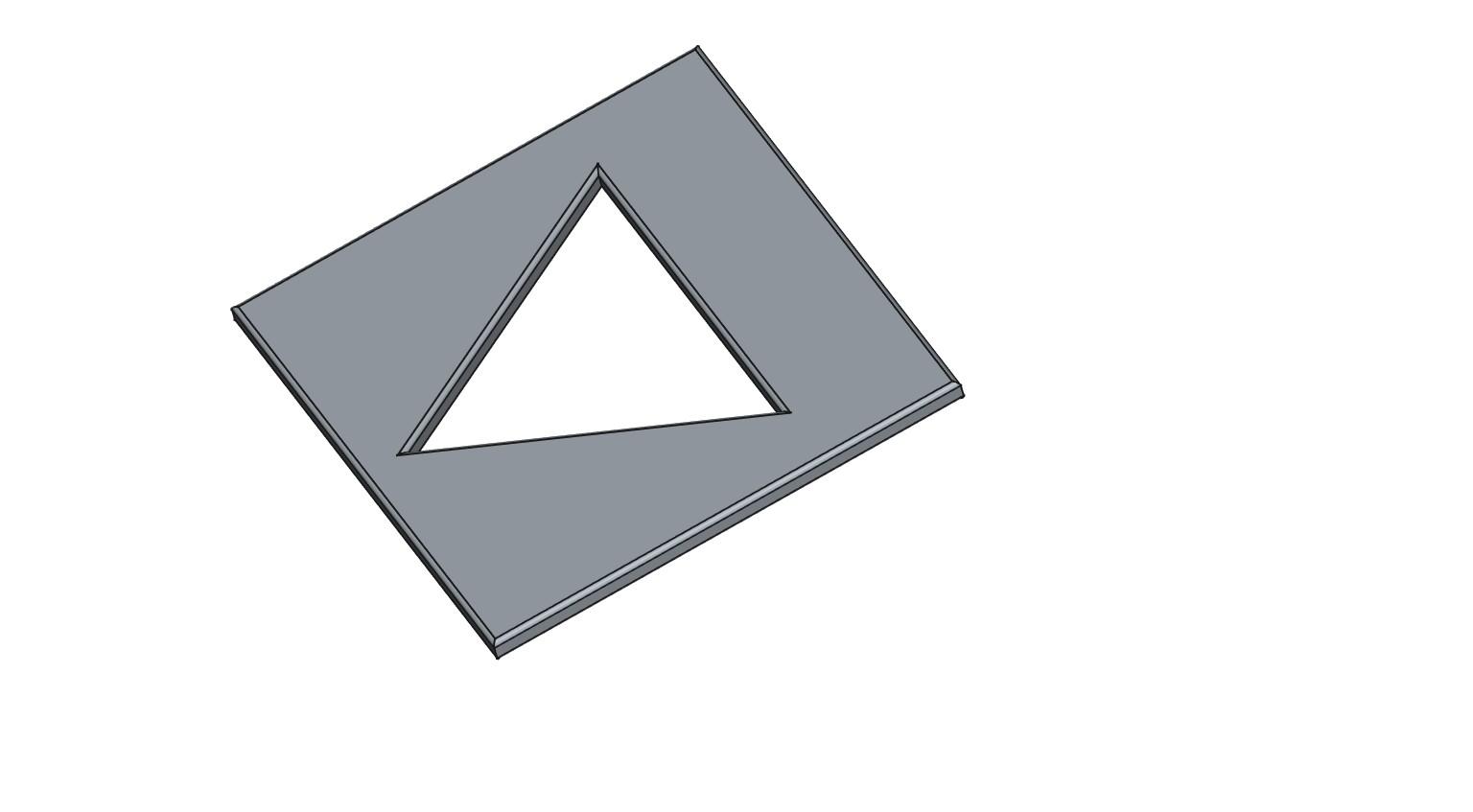
- Insert the “beam-angle” plate into the base-plate.
- Position a beacon such that the two vertical lines converge over the light sensor.
- Rotate the “beam-angle” plate 120 degrees and repeat
Calibrator STL files
The following STL files for this calibrator are attached:
- calibrator_base.stl
- calibrator_beam_angles_1m.stl
- calibrator_beam_direction.stl
An alternate calibrator can be made using a protractor and two equal lengths of string. Join the strings at one end and place the join over the protractor. Now angle the strings such that one is at an angle of 60 degrees to your X-axis, and the other is at an angle of 120 degrees to your X-axis. Place your beacons over the string ends.
The Rotating Laser


The rotating line-laser comprises two sections:
- a spinner
- a motor assembly
The spinner houses:
- a 3 volt battery made from two AAA batteries soldered in series
- a 3 volt line-laser
- and a switch for turning the laser on/off
The motor assembly houses:
- a 6 volt N20 60 RPM motor
- a 6 volt battery made from four AAA batteries soldered in series
- and a switch for turning the motor on/off
Images
Fig.1 shows the motor assembly and the spinner top. The 9mm line laser inside the spinner top is powered from two 1.5 volt AAA batteries wired in series.
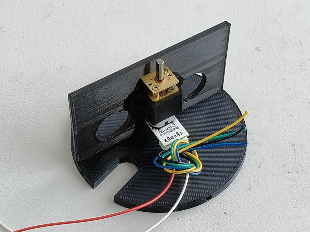
Fig.2 shows the 6 volt N20 60 RPM motor attached to the motor base.
Fig.3 shows four 1.5 volt AA batteries connected to the motor via a switch.
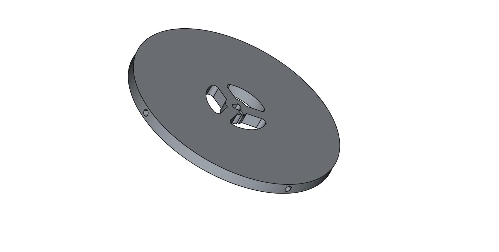
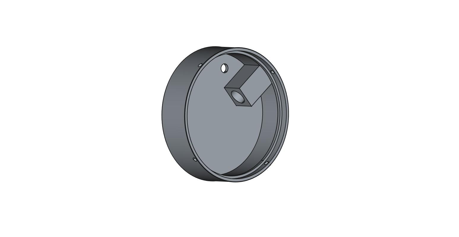
Figs.4 , 5, 6, 7 respectively show:
- The spinner top
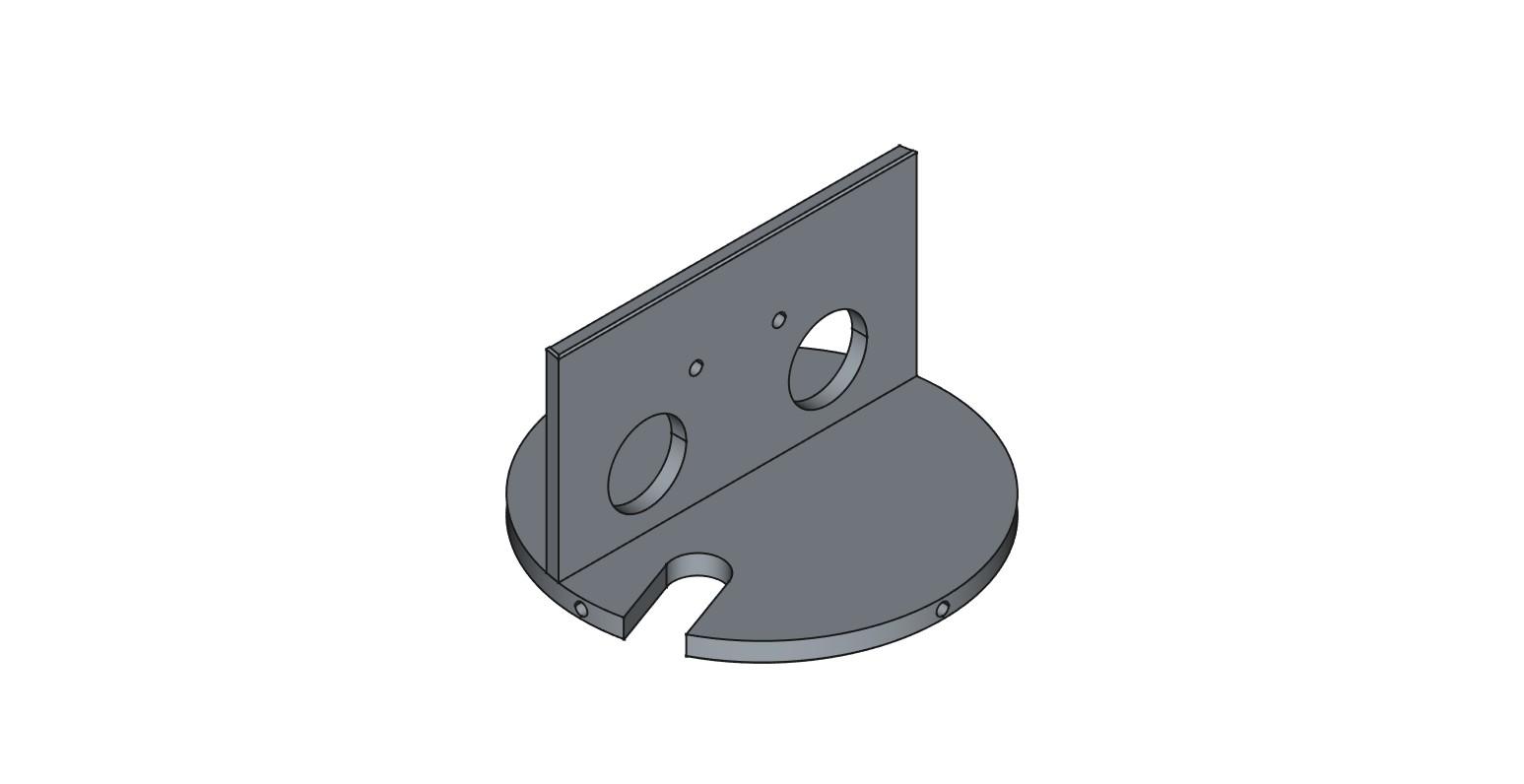
- The spinner base-plate
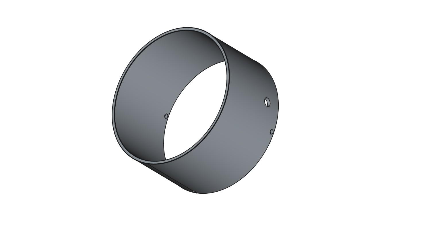
- The motor mount
- The motor sleeve
The Spinner STL files
The following STL files are attached:
- spinner_base.stl
- spinner_top.stl
- spinner_motor_base.stl
- spinner_motor_sleeve
The Receiver


The receiver comprises a three-input “wire-OR” attached to an Arduino.
I originally tried using a 433 MHz receiver module but it generated random pulses. At some stage I’ll sort that issue ... meantime a wire-OR gate gives the same functionality.
The output pulses from the “wire-OR” gate trigger the Arduino pin2 interrupt.
The system is entirely interrupt driven which leaves the main “loop()” free.
Receive Software
Download each of the attached files:
- Robot_triangulation_using_circumcircles.ino
- Robot_triangulation_using_circumcircles.pde
Arduino INO file
Copy the contents of the INO file into a new Arduino sketch using a text editor such as Notepad++ (not a word-processor) and save.
Compile and upload the file into your Arduino
Processing PDE file
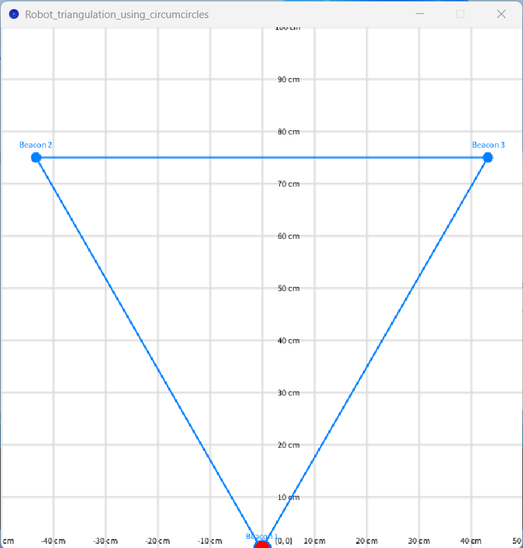
I’ve included a Processing file that shows the robot’s current position.
Copy the contents of the PDE file into a new Processing sketch using a text editor such as Notepad++ (not a word-processor) and save.
Click the “Run” button and the screen shown in fig.3 should appear
Summary
This Instructable explains how the position of a robot can be determined using three beacons and a rotating laser.
The system is entirely interrupt driven which leaves the main “loop()” free.
Construction details are provided for all modules.
In theory the system is 100% accurate ... in practice the accuracy is within one or two millimetres.
This project is purely experimental and is published in the hope that some of the ideas may be of use to others.
The estimated cost of this project is a less than $100.
Click here to view my other instructables.