Rock Paper Scissors Using Tinkercad Circuits and Arduino
by CrazyScience in Circuits > Arduino
23206 Views, 137 Favorites, 0 Comments
Rock Paper Scissors Using Tinkercad Circuits and Arduino


Hi Creative people! In this Instructables I will show you how I made a rock paper scissors game, Yes you heard it right!
Remember those days we used to play rock paper scissors for decision-making?
What were those good olden days, Those days are unforgettable, as we get older we will have only a few friends left, and some end without any friends.
This may seem funny but it is the harsh truth and most of them might have already experienced this.
Now you may ask why am I telling all these? The answer lies within this project.
I made this as an interactive project as well for a few who are introverts or struck with boredom.
'This is a friend for you who never cheats in decision making otherwise your friends used to! when they play rock paper scissors.
Outline of this project
This circuit for this project was made using Tinkercad Circuits followed by simulation using the same software
Advantages of Simulation
Think of a project where you build it without any virtual testing, in the end, if the project fails you might end up wasting time in the process.
To eliminate all these dramas I suggest using simulators.
In this project I used the Tinkercad Circuits simulator to build and test the circuit, Later i converted that virtual project to a physical project using real electronic components.
This assures 100% flawless working of the project so you can save time and money.
Note: Thanks to WWW.LETSMAKEPROJECTS.COM for arduino Codes
What Does our Project do?
As stated earlier rock paper scissor needs 2 people to play the game, here you are one person and the other is this device.
Thank You NextPCB:
This project is completed with amazing success thanks to NextPCB support. If you have any PCB projects please visit their website to get attractive discounts.
- Only 0$ for 5-10pcs PCB Prototypes:Nextpcb.com/pcbprototype
- Register and get $100 from NextPCB: Nextpcb.com/coupon
Why NextPCB
- Most Efficient, Economic, Innovative PCB Solutions
- Higher Quality
- Lower Cost
- Faster Delivery
This is an interactive device and this can be used to have a great family time!
This works as a perfect replacement for your friend!(kidding)
Just show your signs in front of this device and see what the machine gives out.
There is no chance of cheating from the device end as the servos are coded to appear randomly.
With this being said let us head toward building this project.
Supplies
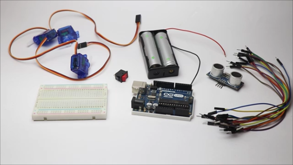
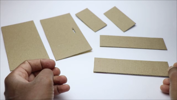
Here is the list of materials you will need to build this project also I have given buying links
- Tinkercad
- Arduino IDE
- Computer/laptop with internet connection
- Cardboard to make the frame
- Arduino UNO Get from here
- programming cable
- Plastic Servos x 3 from Here
- Simple on-off switch
- Rechargeable batteries/18650 or lithium-ion batteries
- Battery holder
- Small Breadboard
- Jumper wires
- Ultrasonic sensor and jumper wires from here
- Hot glue
- Super glue
- Black fabric paint
- Transparent tape
You can get the product from my links above so that you are supporting me at no additional cost to you.
Simulation Using Tinkercad Circuits Editor

Before building a real model I used Tinkercard to make the circuit.
VIDEO: I have recorded the simulation video and attached it to the end of this step to show how exactly it works so that you have a clear idea about its functionalities.
To avoid any room for confusion I have added a video of using the simulator after building the circuit.
It is very simple and easy to build a circuit all you need to do is drag and drop the components, connect them with colorful wires, and upload the code in text form.
I already wrote the code and just fed those code.
Just enable the simulator to check if the code is working.
The code works perfectly fine and i have given the same codes for you to play with.
Kindly refer to below steps for code.
As per the code, the motion of servos is random so the next move of the servo can't be determined.
Rock Paper Scissors Circuit Diagram

The circuit used to make this project is shown above
It is simple and easy, if you find any difficulties in reading the circuit here is the written explanation for circuit building
Ultrasonic or HC-SR04 sensor Connections
It has 4 set of pins that are Gnd, Trig, Echo and Vcc
Gnd and Vcc are for negative and positive power supply and these are directly connected to - and + rails on a breadboard
Trig is connected to D11 pin on Uno
Echo is connected to D10 pin
Arduino uno Connections
Power supply to all the components is provided by Uno board
So we will connect Gnd of Uno to - rail of breadboard
5v of Uno to + rail of breadboard
Gnd and Vin pin of Arduino will be used for external power supply from the battery
Micro servo connections
We will use 3 micro servos in this project
Each micro servo has 3 input pins
Positive, Negative and Signal pin
Positive and negative pin of all 3 servos will be connect to + and - rails of the breadboard
While the signal pin of servos will be connected to D3, D6 and D9 pins on Uno
This completes the circuit
Making Connections
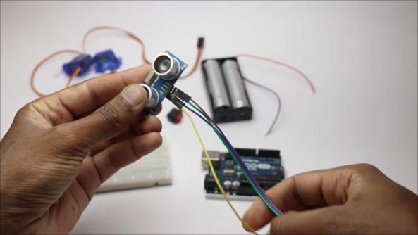


As we have already gone through the simulation and circuit building the circuit won't be any difficult job
Start by connecting jumper wires to the components followed by connections with the breadboard
Avoid using loose jumper wires while making the connections because if you do and in the end, if any components did not work it is a difficult task to find the exact spot resulting in wasting time
After you build the connections between all the components we are ready to upload the code
Arduino Code for Rock Paper Scissors


Here is the Arduino code for Rock paper Scissors the same code was used in the simulator
You can download this code and open in Arduino IDE
Connect UNO board with the programming cable and check for the proper port in IDE by going to menu - tools - port
Select the port, select the type of board and click on upload
Once the board is uploaded with the code we can test the circuit
Note: I recommend not to use power from Arduino USB instead use a separate power source like I did from the battery
second image on this step shows pins that are alloted to micro servos
Making Frame


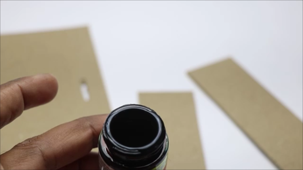

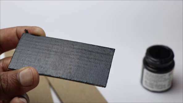
To hold all the electronics I made a case out of cardboard, as the electronic components come in standard sizes you can use these dimensions without worrying about fitting issues.
I used the pieces of these dimensions
For the base and Top 2 pieces of 15 x 8cm
For sides 2 pieces of 15 x 4cm and edges 8 x 4cm
You can use this cardboard but to give it a more appealing look i painted them black using fabric paint
Did You know?
If you don't have a paint brush and wat to paint cardboard you can use earbuds / ear swabs, These work just fine for painting cardboard
Building Frame
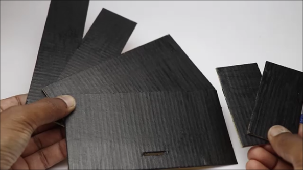

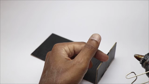
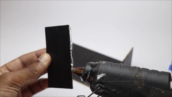
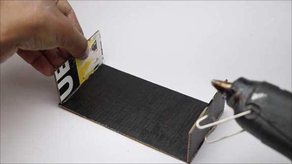

Once the cardboard-painted areas are dry we can assemble them, I don't suggest you use super glue for sticking because in case if you miss any spot after applying superglue the surface becomes very hard, and applying glue again ti the same spot won't serve any better
I recommend to use hot glue, here follow the images on the steps provided, start with the base later the edges
To enhance the strength add hot glue for the corners too
Adding Components Inside Frame


After we have our frame ready we can add electronics that we already assembled earlier.
Before fixing the components inside the frame test the circuit for working, if you miss anything fix it first.
To avoid slipping any components use a tiny amount of superglue before placing the components in the base.
I will be adding a battery holder and breadboard to the base whereas Arduino sits on top of the small breadboard.
Add a switch between the battery and Arduino board, this simple switch should be providing power at the press of a button
The last image of this step shows a bird's eye view of all the components that are in the box.
Now the base part is read, we will work on the top part in the next step.
Set Top Part

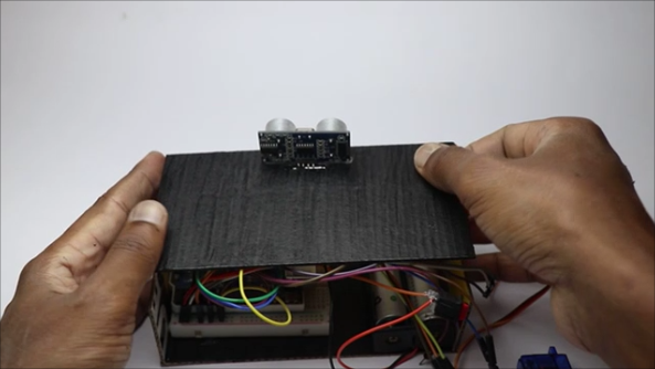


The top part has all the working components like servos which is the most important part of our project
We will add an ultrasonic sensor first to the top lid (made from cardboard earlier)
I have made a small slot in the cardboard to add this sensor, you can make it on the exact spot to
Use hot glue to couple everything together
Now our top part is ready, before gluing the servos on top switch on the device first and check for servo movements
You cannot skip this part and directly glue it because the wrong placement of the servo results in improper movements
check for movements and stick the servos to top
End of this process we have almost the project ready to be finished
Finishing

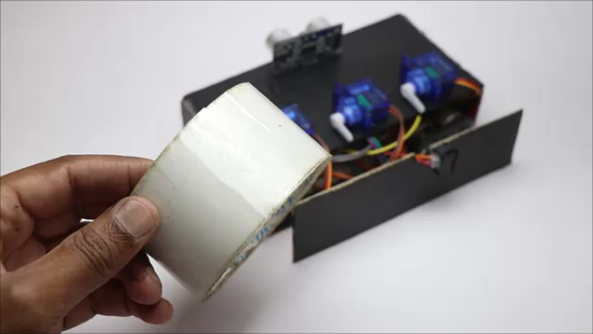


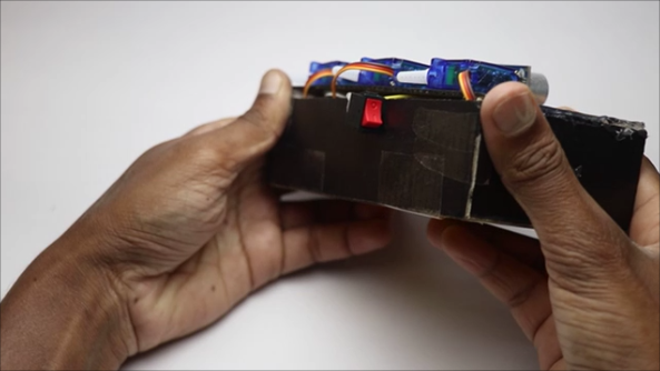

You know and i know that this project used lots of jumper wires and leaving them outside makes the project look messy.
So finishing will make this look a lot cleaner.
Since we are using rechargeable batteries after a long period of using this device battery needs to be charged, for this purpose we need a system to open and close the frame
For this purpose, one side of back frame is coupled using transparent tape/ duct tape so that we have access to the battery and circuit whenever needed
Have a look at those placements of switches shown in above images
Adding Signs


I have cut strips of cardboard that are 1cm x 11cm that will be added to the horns of the micro servo, I had a plan of 3d printing most of the parts for this project but as most of them won't have a 3d printer at their house I made using cardboard.
Now this can be made by anyone as everyone has access to cardboard
Rock, paper, and scissors signs/symbols I have hand drawn on a piece of paper
Stick these signs to the tip of the cardboard stripes, now with the help of superglue connect these strips to the horns of the micro servo
once you have the glue completely dry test this device, obviously it should work without any issues
How to Use
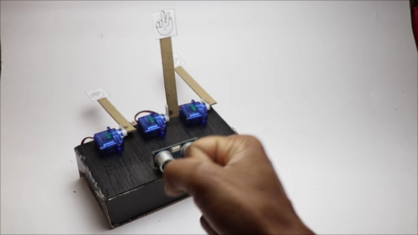
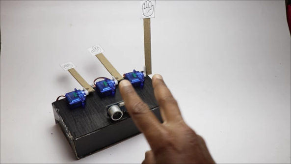
It is very simple to use this device
- Just switch on the button and wait for 2 seconds.
- Now just bring your hands close to the sensor and start making rock paper or scissor signs
- The device shows its own signs
- Now you have a tough competitor!
- The signs from the device will be random hence you can't predict the next move
- Take this device to family time parties or your friend's house to impress them.
Have fun!
Rock Paper Scissors Game Working Video

You can refer to this video tutorial if you have any questions on any steps, if this still didn't help there is always a comments section to get in touch
Thank you for reading till here and Happy making.
If your browser is unable to play this video directly paste this link on your url search tab https://youtu.be/Rsipdg-W-uE