Rolling Ball Oscillator
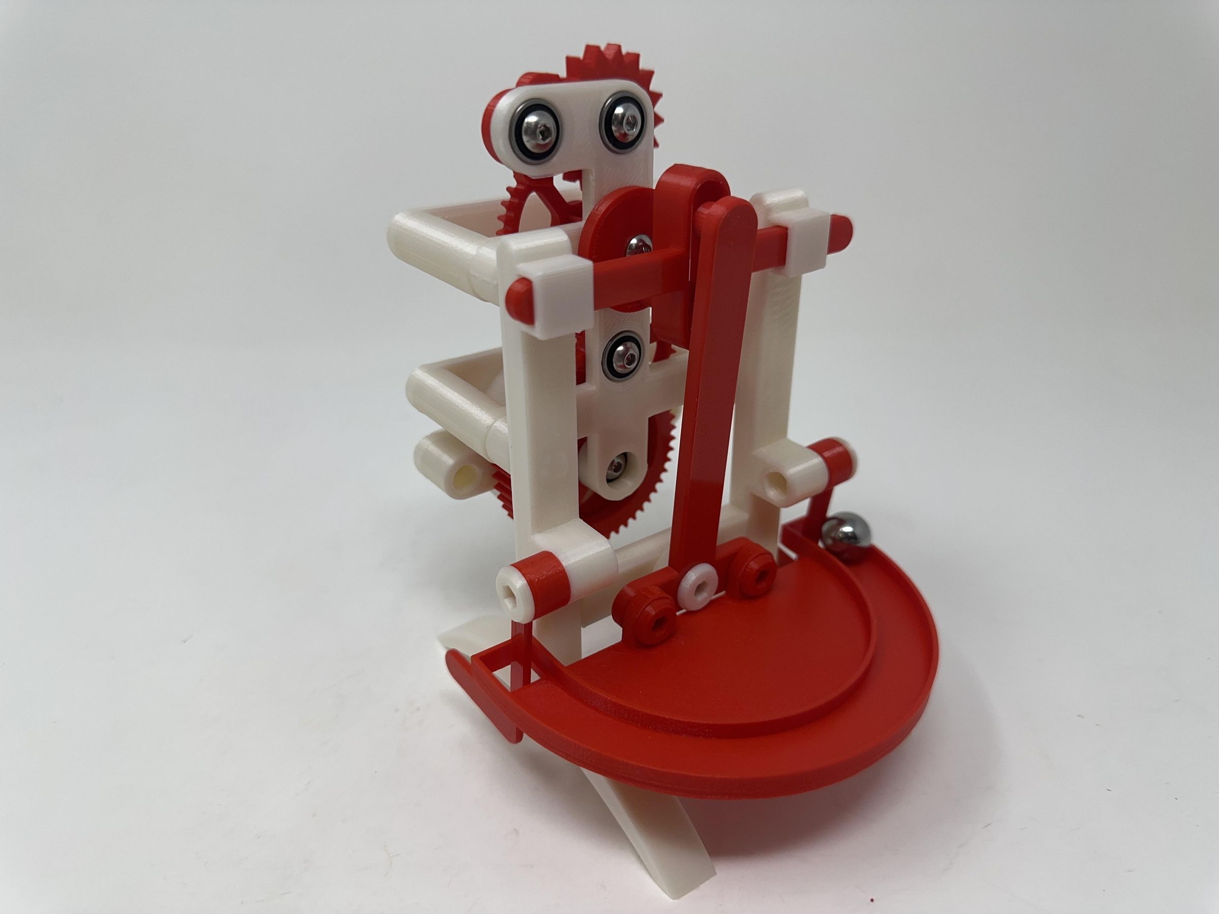
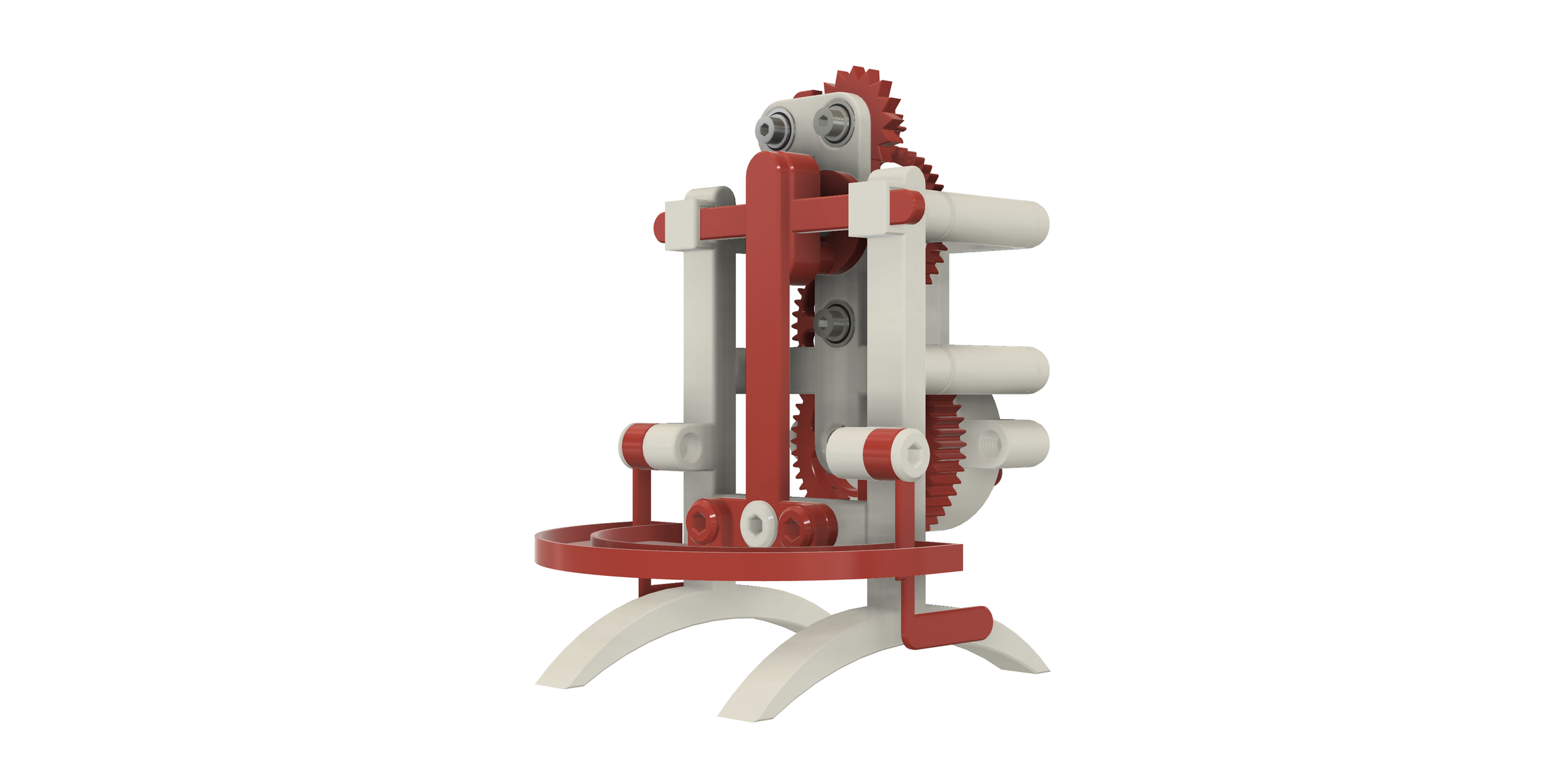
"Rolling Ball Oscillator" was inspired by a rolling ball escapement clock my wife and I saw on the television show "The Repair Shop". As mentioned in the show, rolling ball escapement clocks are quite inaccurate due to how level (or perhaps un-level) the surface is that they are placed on, as well as dust and grime that can accumulate over time on the track. I found, however, the concept to be so intriguing that I designed, 3D printed and assembled "Rolling Ball Oscillator" in order to understand the conceptual and design requirements for such a mechanism. I replaced the term "Regulator" with "Oscillator" as this model slows as the spring motor runs down.
As usual I probably forgot a file or two or who knows what else, so if you have any questions, please do not hesitate to ask as I do make plenty of mistakes.
Designed using Autodesk Fusion 360, sliced using Ultimaker Cura 4.12.1, and 3D printed in PLA on Ultimaker S5s.
Supplies
Thick cyanoacrylate glue.
Allen wrench set.
Jewelers file set.
Tap and die set.
Parts.
I acquired the following parts:
- Seven 4mm ID, 12mm OD, 4mm thick deep groove ball bearings.
- Ten M4 washers (4.25mm ID, 8mm OD).
- One Cap Screw (M4 by .7 by 10mm).
- Two Cap Screws (M4 by .7 by 12mm).
- Two Cap Screws (M4 by .7 by 20mm).
- One Cap Screw (M4 by .7 by 25mm).
- One .5" diameter ball bearing.
- One "Incredible Candle" spring (scan the barcode image for details). To remove the spring from the candle, after the candle rotation stopped, I carefully pried the spring cover off the bottom of the candle then removed the spring from the spring housing.
I 3D printed the following parts at .15mm layer height, 20% infill, no supports in PLA:
- One "Arm, Release, Left.stl".
- One "Arm, Release, Right.stl".
- One "Arm, Rocker.stl".
- Two "Axle, Arm, Release.stl".
- One "Axle, Arm, Rocker.stl".
- One "Base Crossmember.stl".
- One "Base Tower Left.stl".
- One "Base Tower Right.stl".
- Four "Bolt (M8 by 1.25 by 8).stl".
- Four "Bolt (M8 by 1.25 by 50).stl".
- One "Cam.stl".
- One "Gear Plate.stl".
- One "Gear, Compound 1 (1m, 40t, 10t).stl".
- One "Gear, Compound 2 (1m, 40t, 10t).stl".
- One "Gear, Escapement, Compound (1m 10t).stl".
- One "Gear, Pawl (1m, 50t).stl".
- One "Knob.stl".
- One "Pallet.stl".
- One "Pawl.stl".
- Four "Spacer (10mm).stl".
- One "Spring Housing Cover.stl".
- One "Spring Housing.stl".
- One "Spring Mount.stl".
- One "Track.stl".
- One "Yoke.stl".
This mechanism is a high precision print and assembly using at times very small precision parts in confined spaces with highly precise alignment. Prior to assembly, I test fitted and trimmed, filed, drilled, sanded, etc. all parts as necessary for smooth movement of moving surfaces, and tight fit for non moving surfaces. Depending on your slicer, printer, printer settings and the colors you chose, more or less trimming, filing, drilling and/or sanding may be required to successfully recreate this model. I carefully filed all edges that contacted the build plate to make absolutely certain that all build plate "ooze" is removed and that all edges are smooth using small jewelers files and plenty of patience.
This mechanism also uses threaded assembly, so I used a tap and die set (M8 by 1.25 and M4 by .7) as required for thread cleaning.
Downloads
Assemble the Spring Housing.
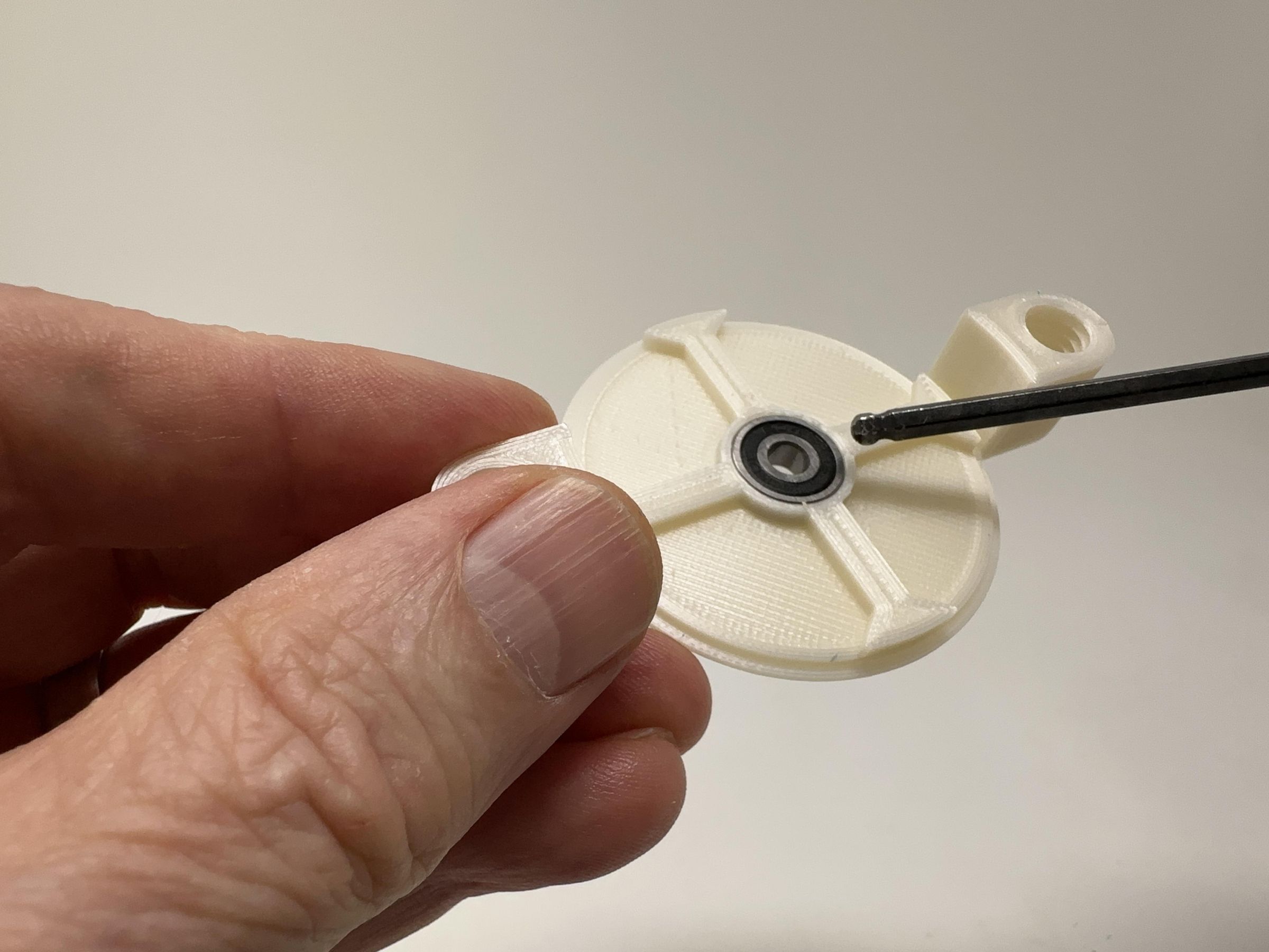
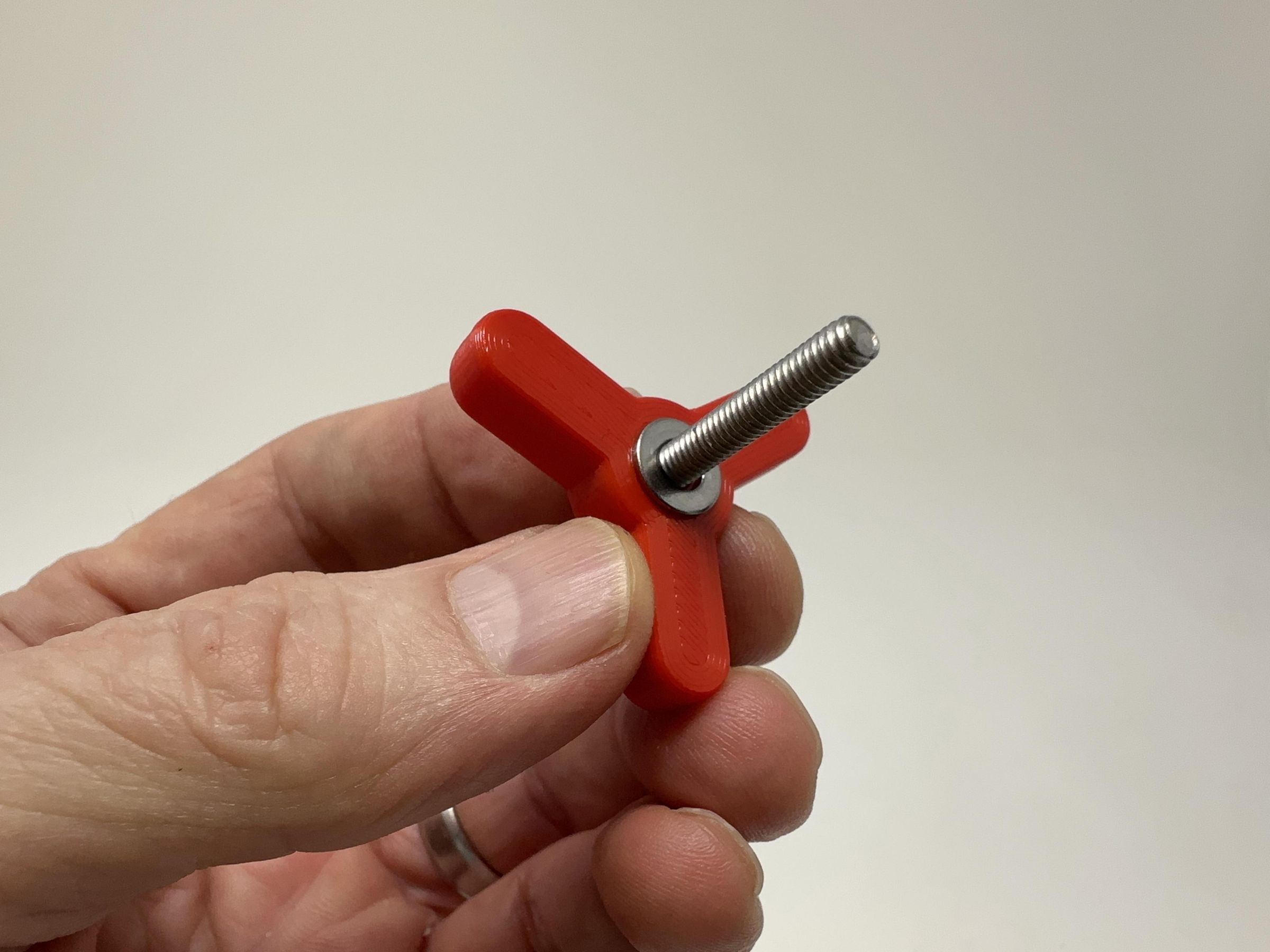
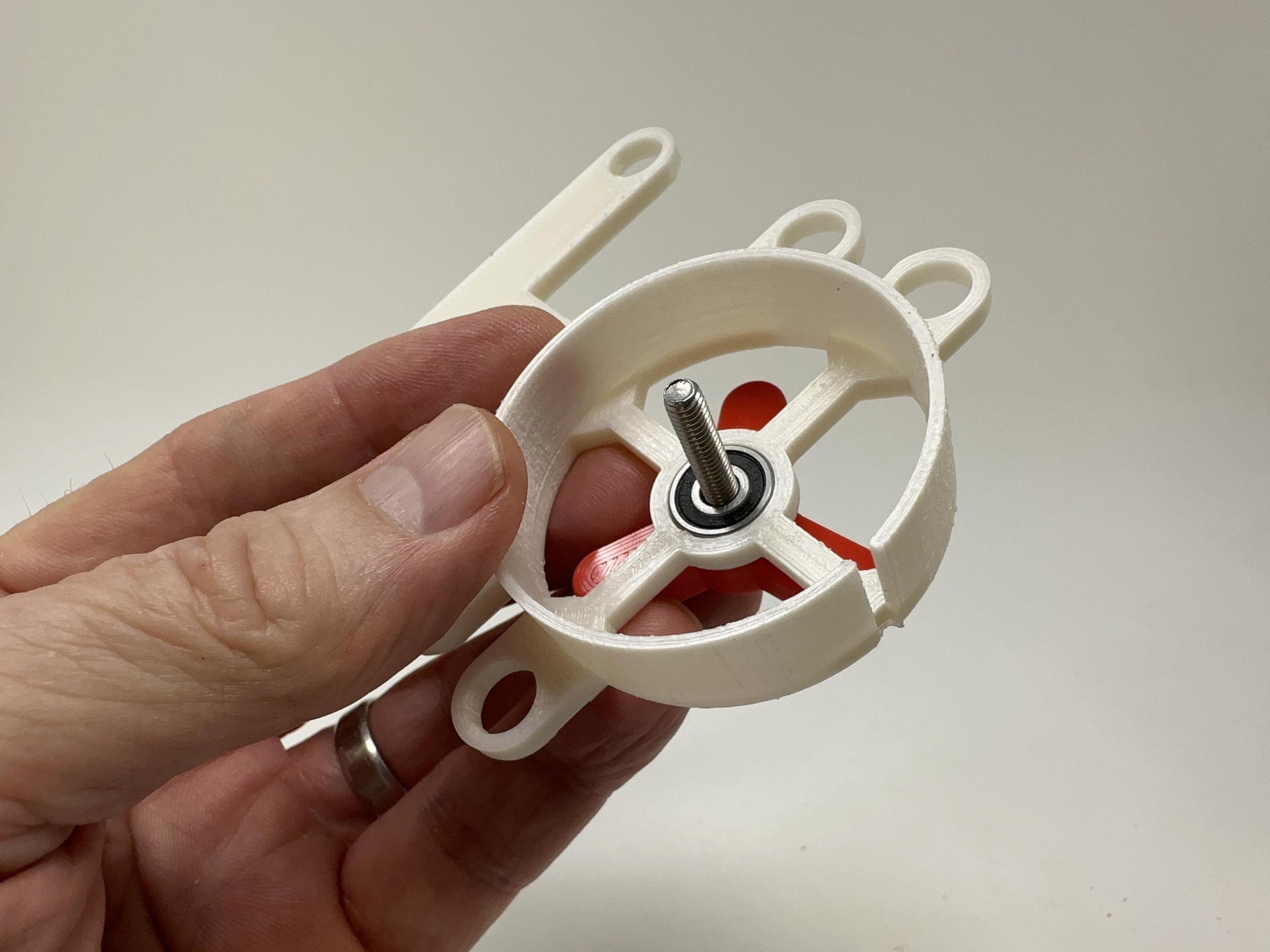
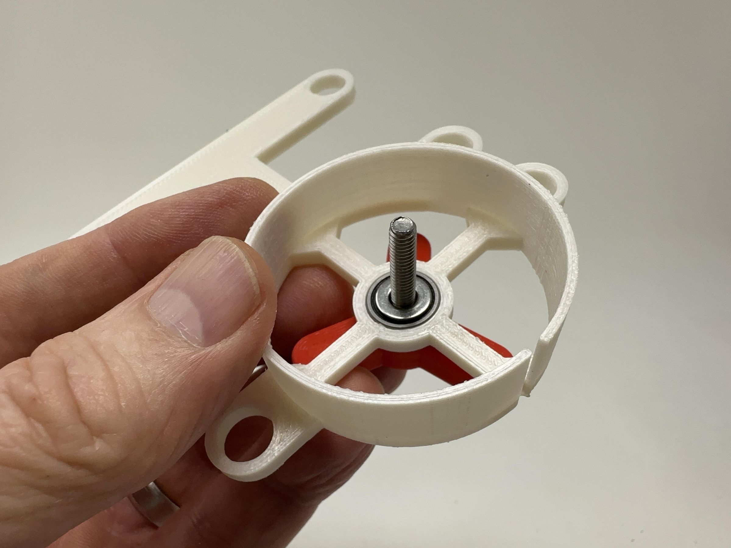
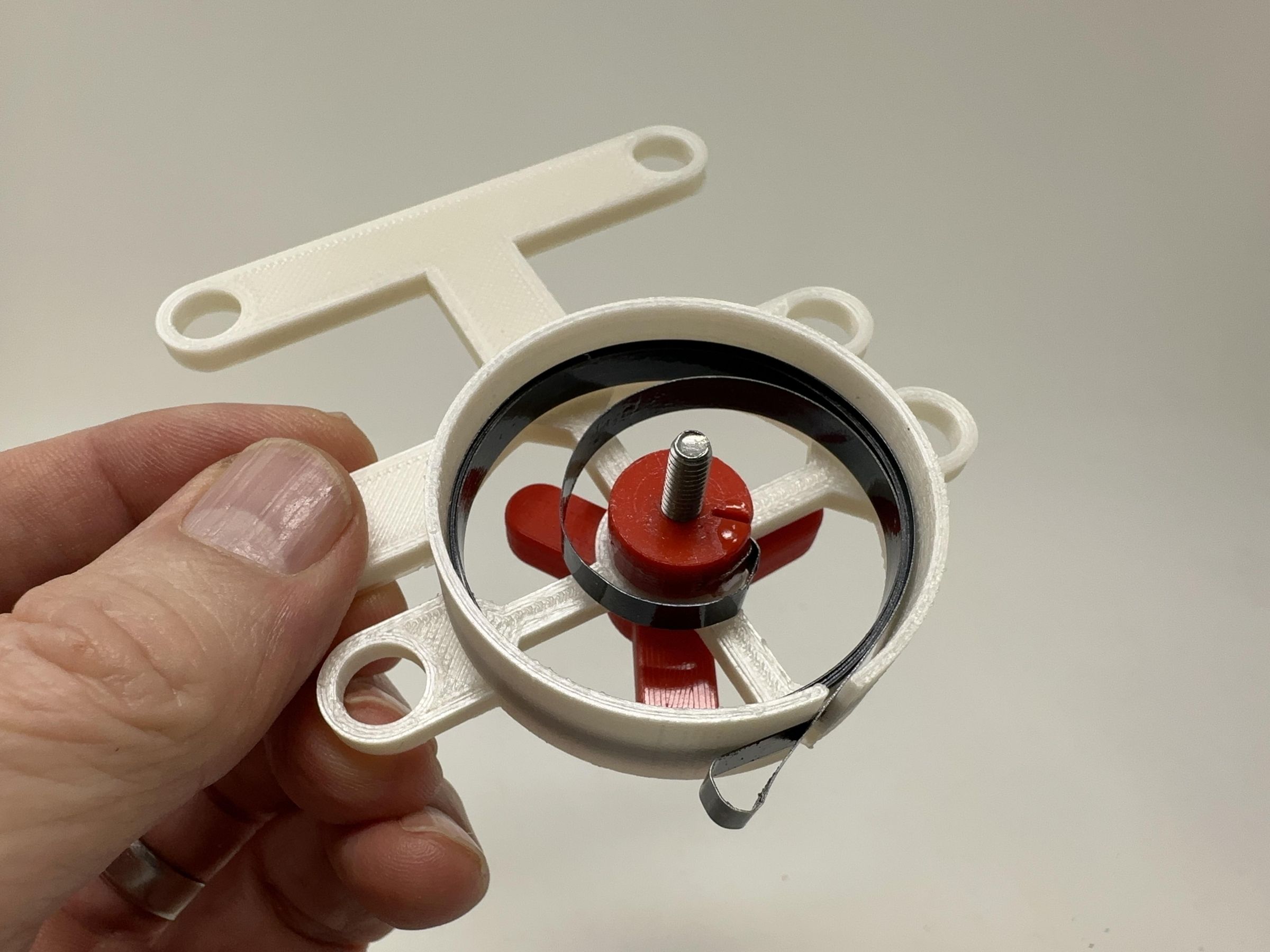
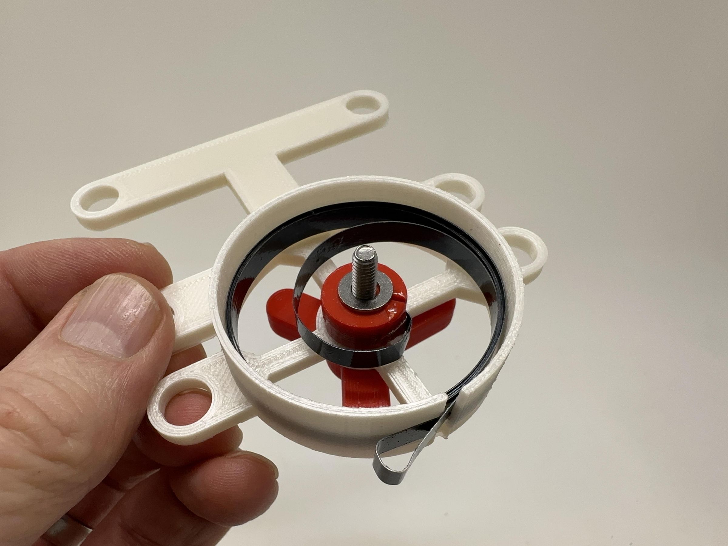
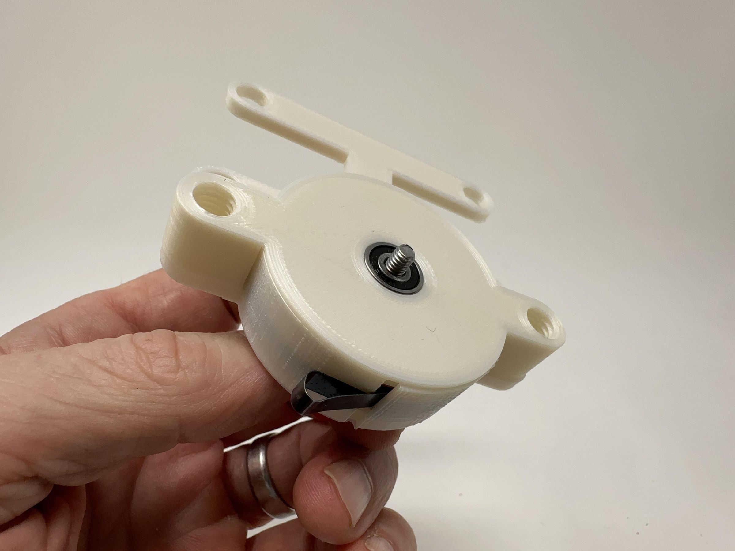
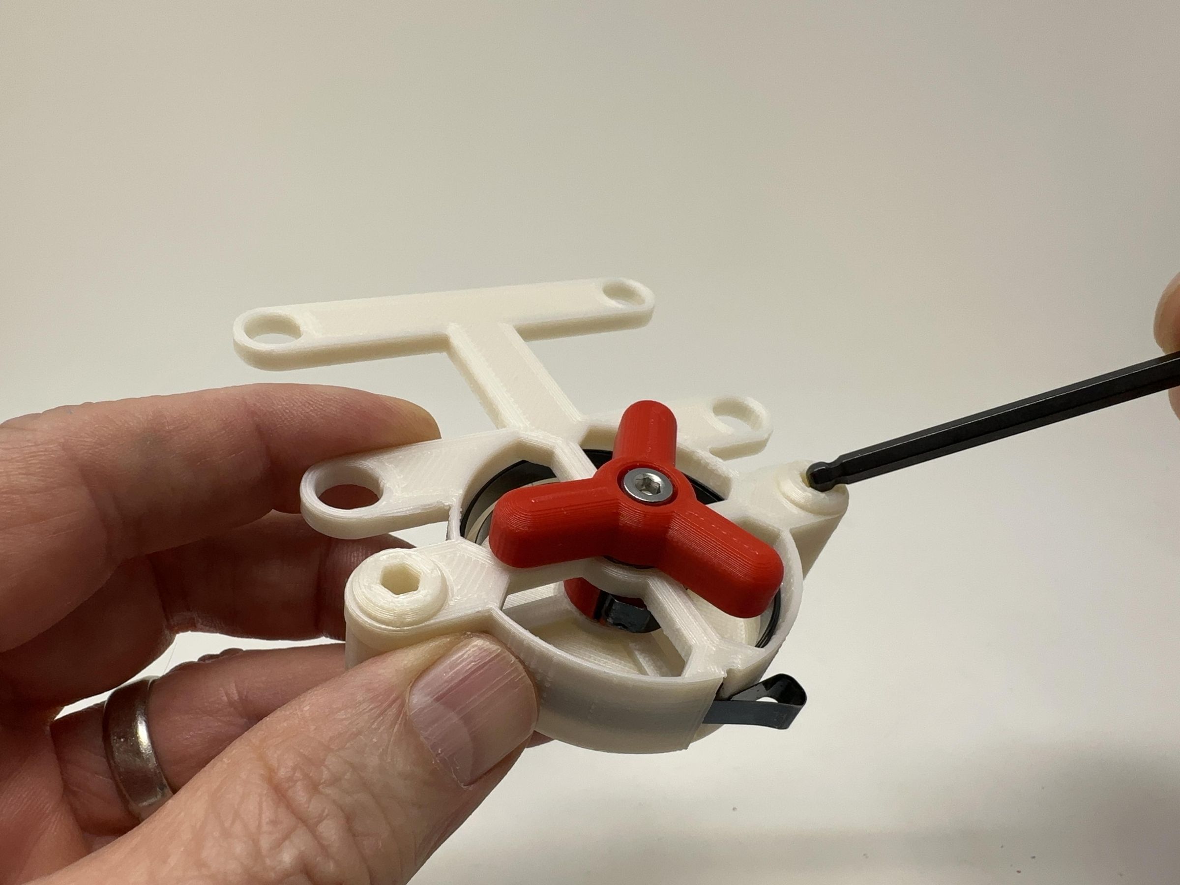
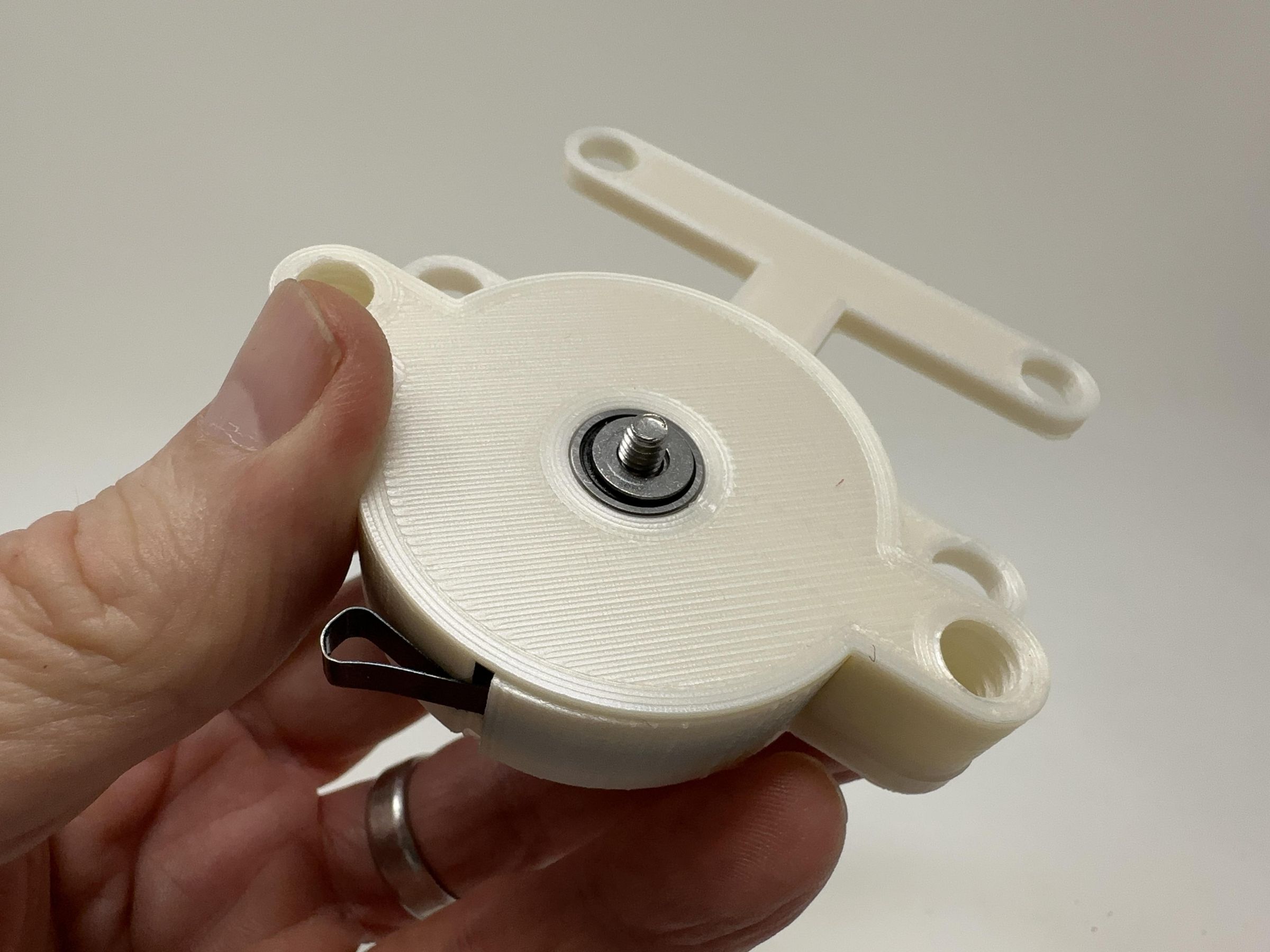
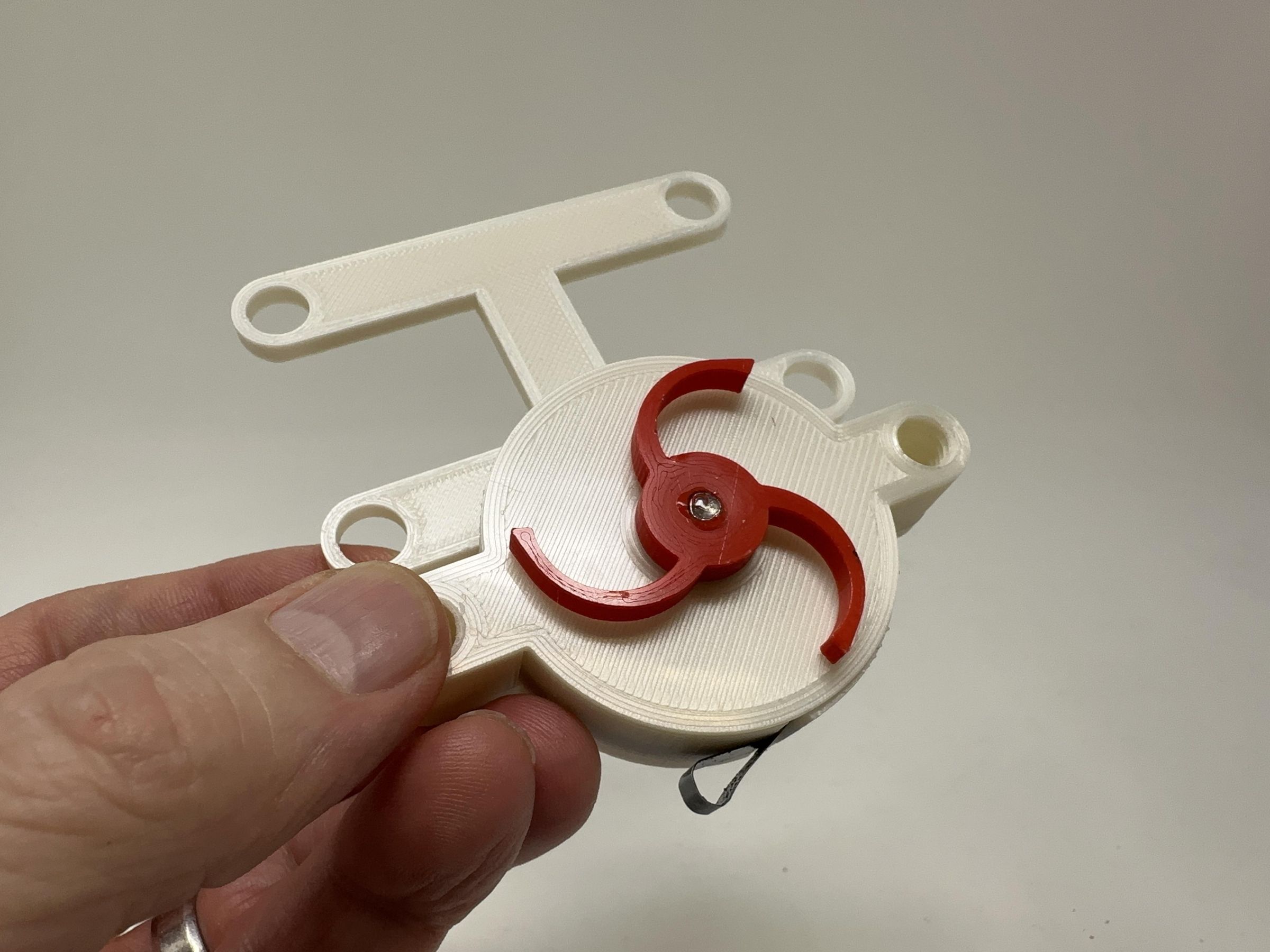
To a assemble the spring housing, I performed the following steps:
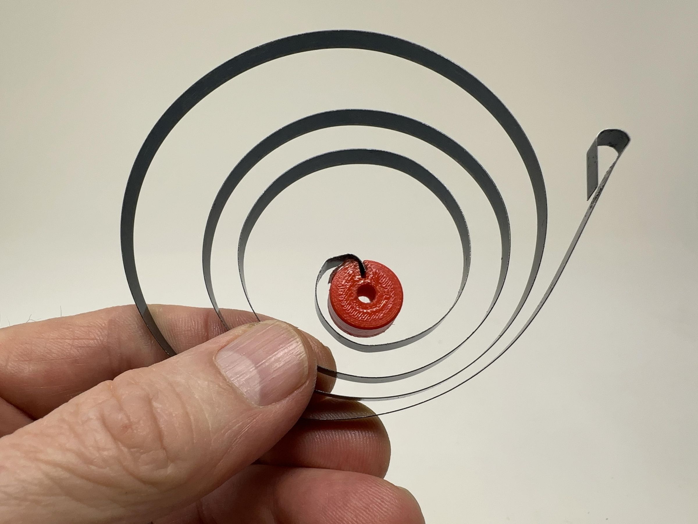
- Glued the spring removed from "Incredible Candle" to "Spring Mount.stl" in the orientation shown.
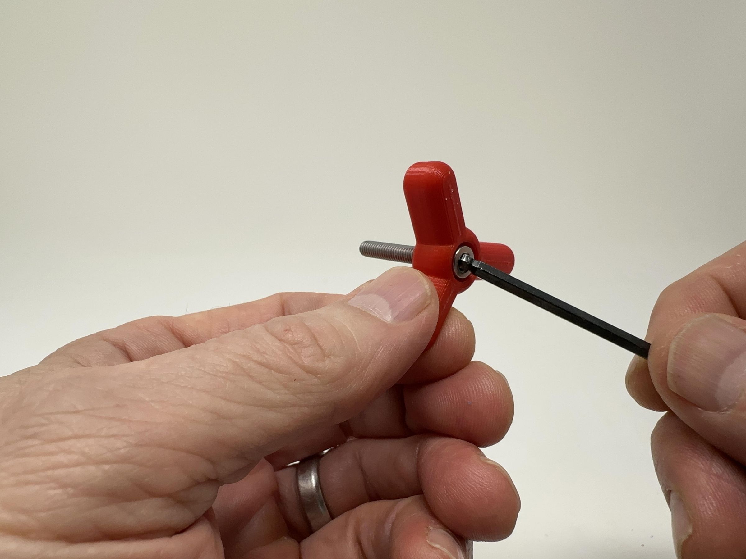
- Threaded one 25mm cap screw into "Knob.stl".
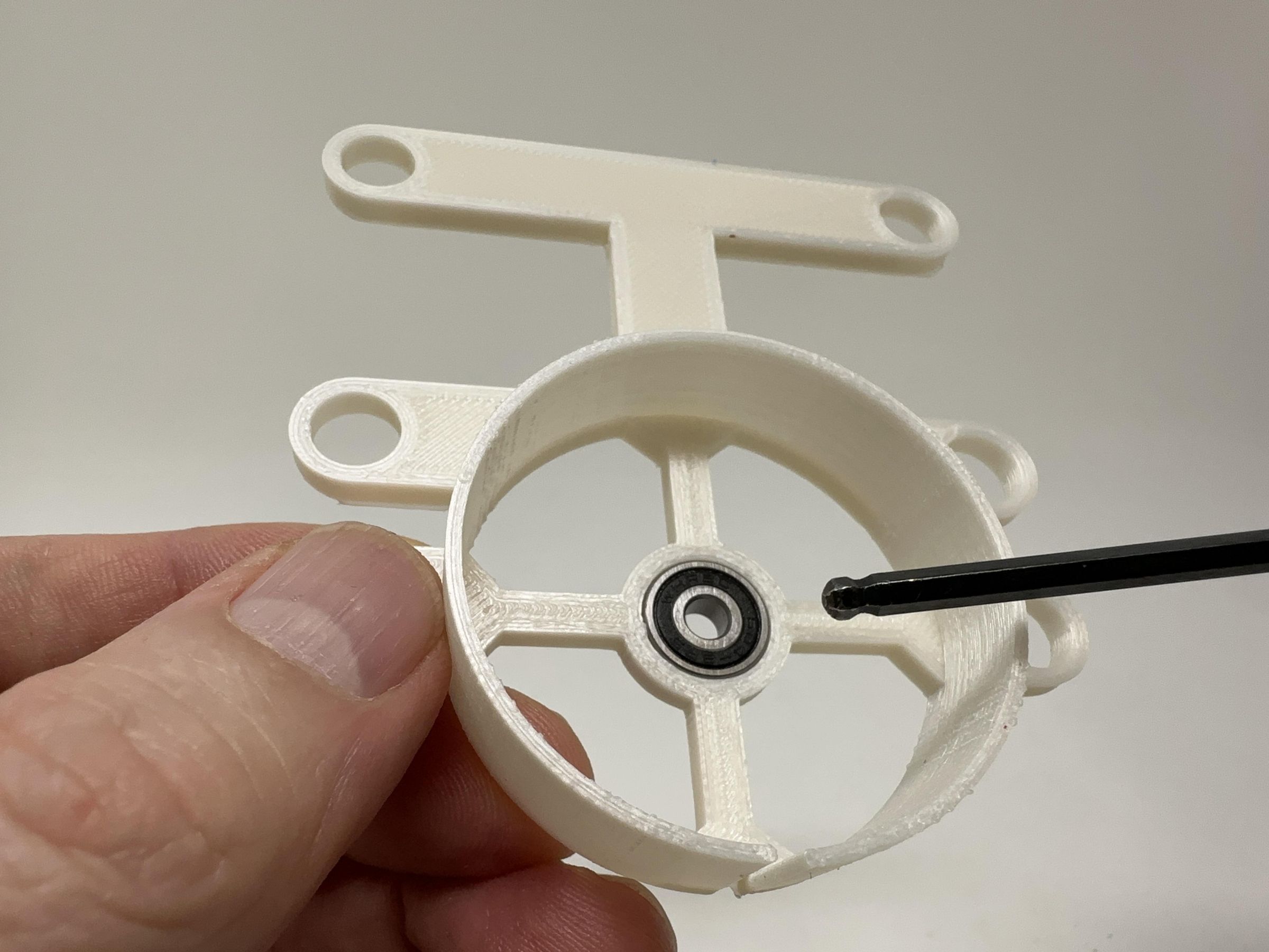
- Pressed one deep groove ball bearing into "Spring Housing.stl".
- Pressed one deep groove ball bearing into "Spring Housing Cover.stl".
- Placed one m4 washer onto the knob cap screw.
- Slid the knob cap screw into the bearing in the housing assembly.
- Placed one m4 washer onto the knob cap screw.
- Placed a drop of glue in the spring mount threads, then threaded the spring mount assembly onto the knob cap screw making certain it was fully tightened.
- Placed one m4 washer onto the knob cap screw.
- Placed the spring housing cover assembly onto the spring housing assembly then secured it in place using two "Bolt (M8 by 1.25 by 8).stl".
- Placed one m4 washer over the knob cap screw.
- Placed a drop of glue in "Pawl.stl" threads, then threaded the pawl onto the knob cap screw making certain it was fully tightened.
Assemble the Gear Plate.
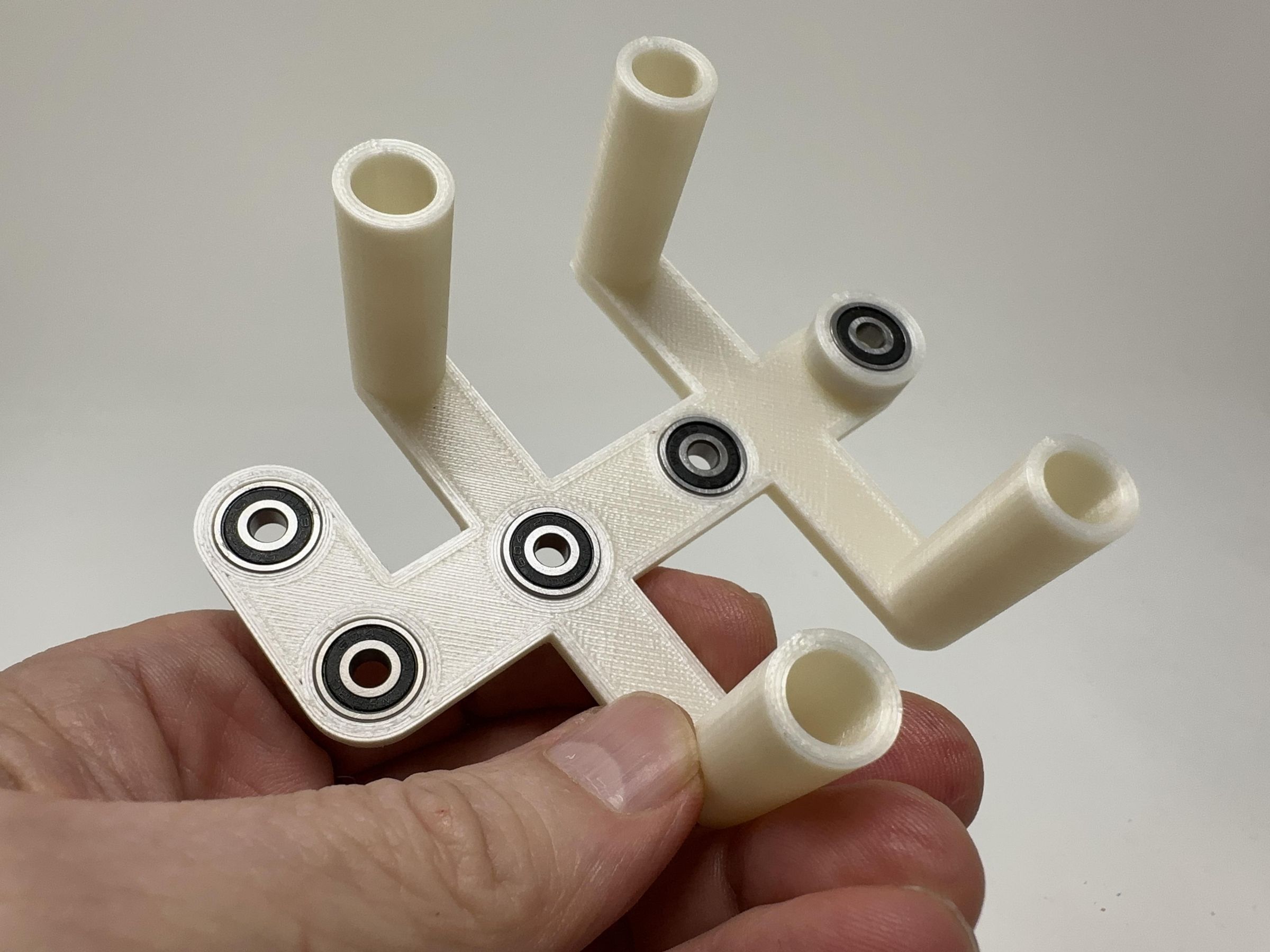
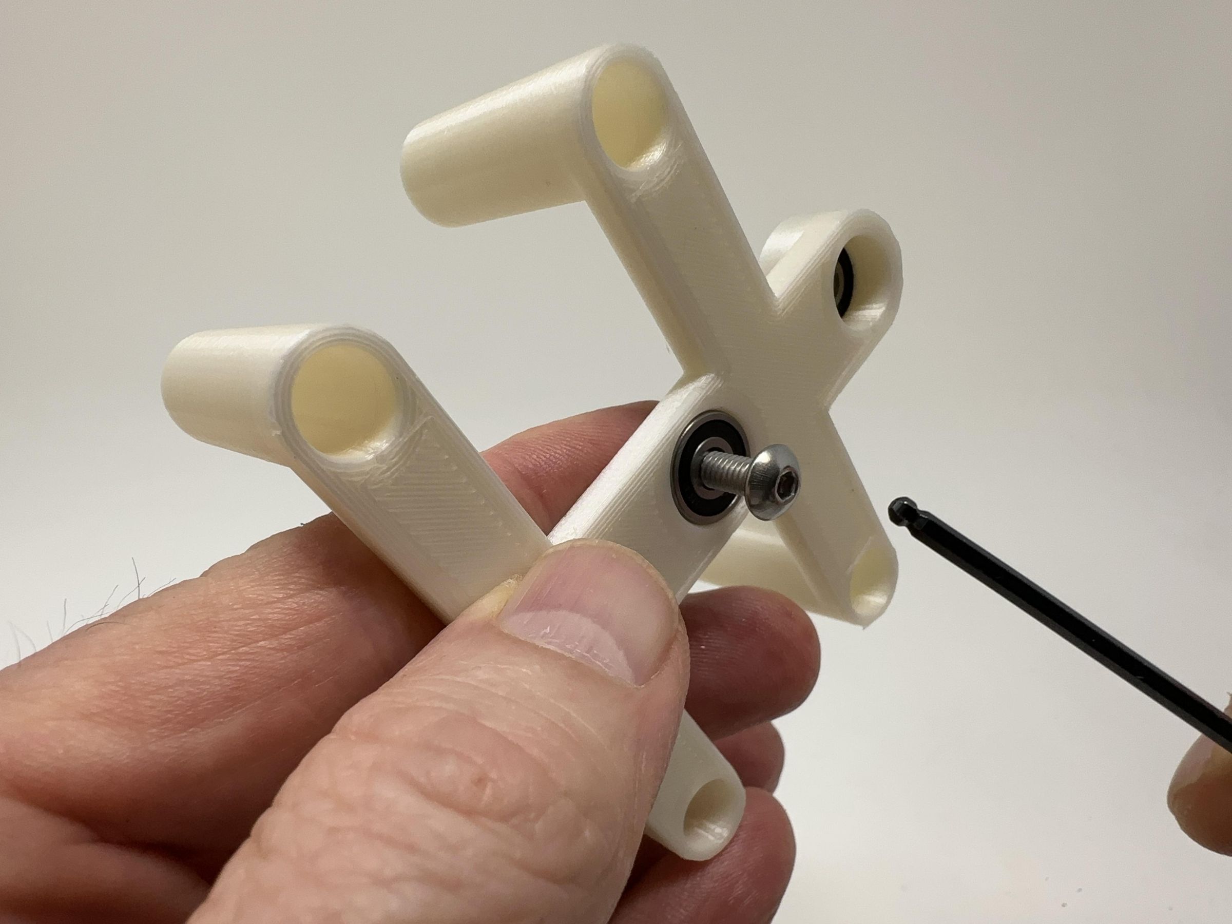
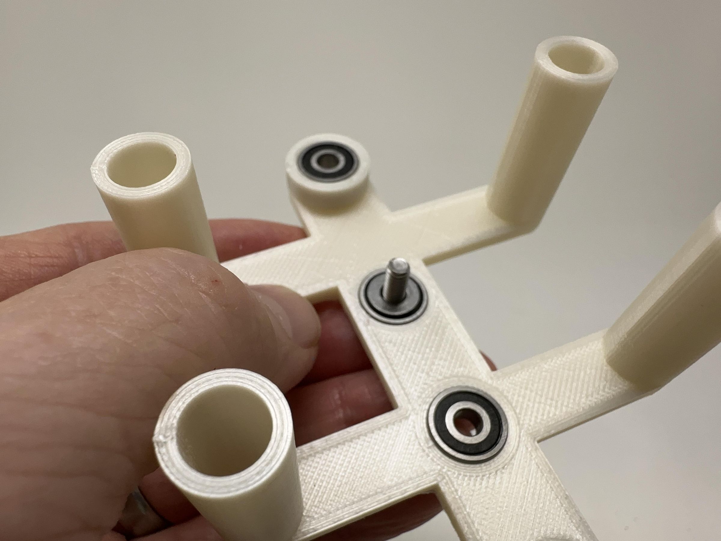
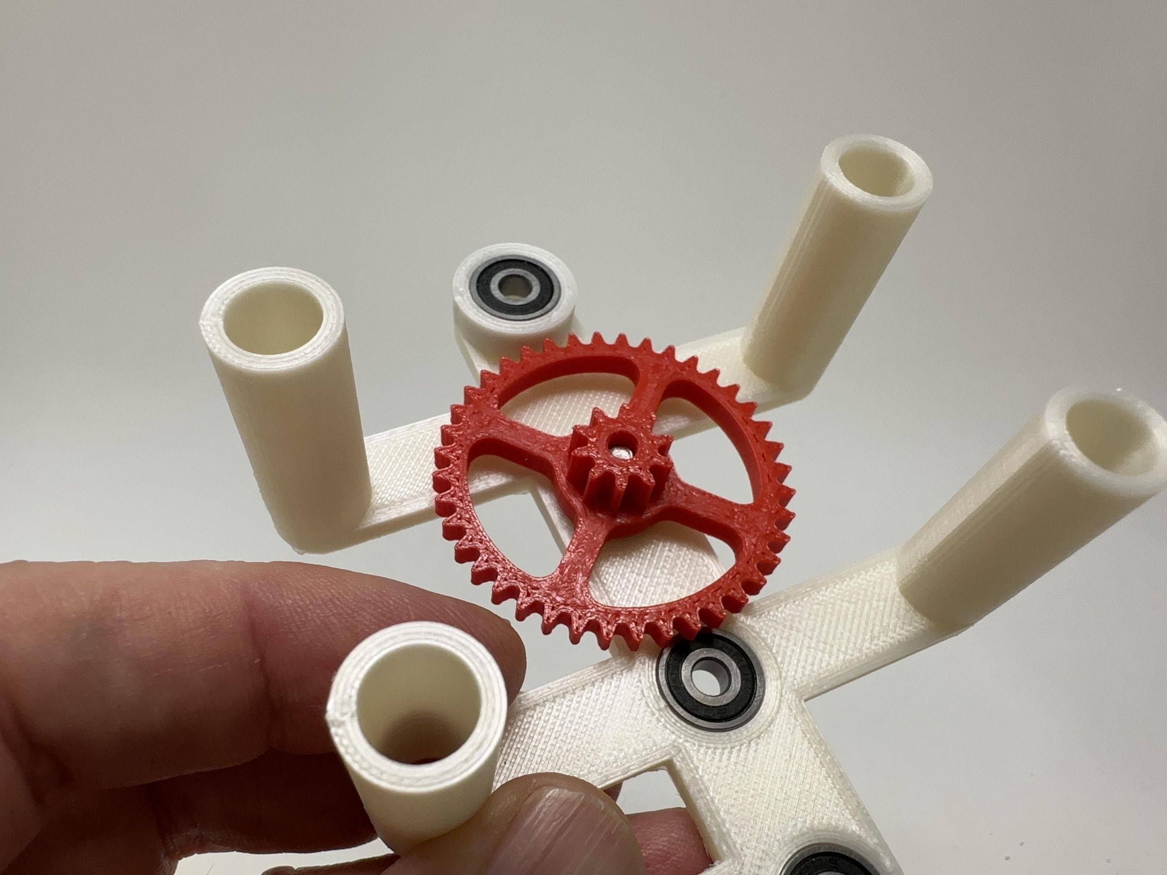
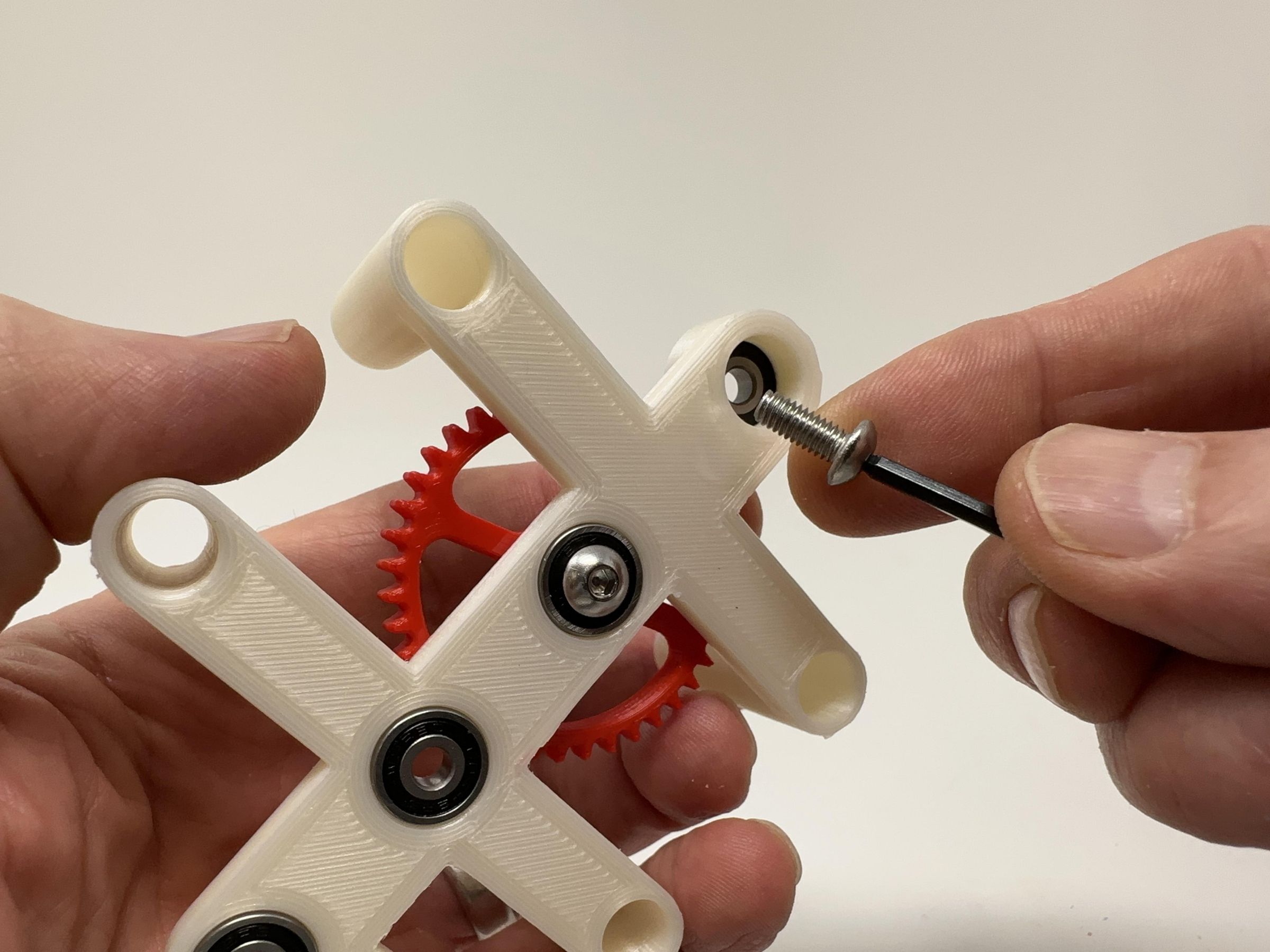
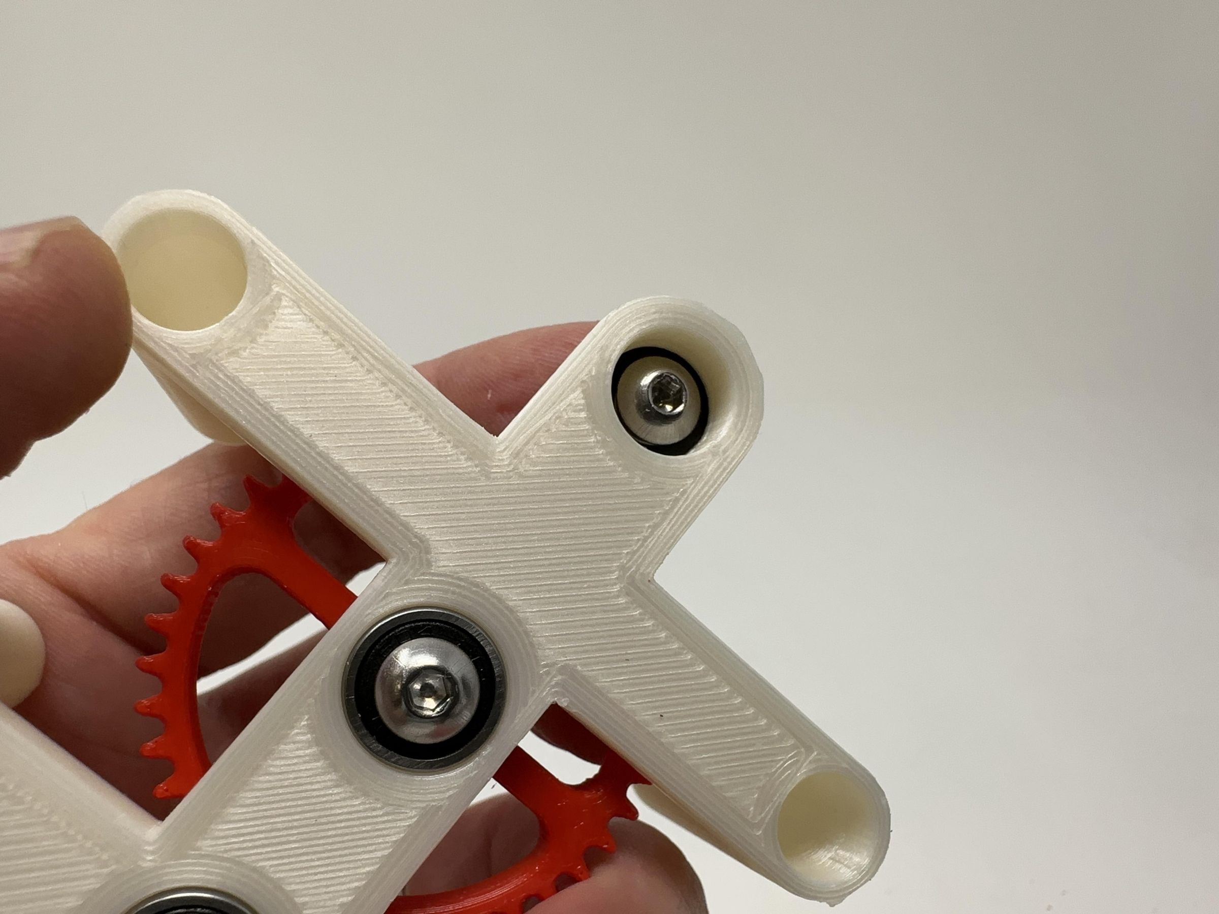
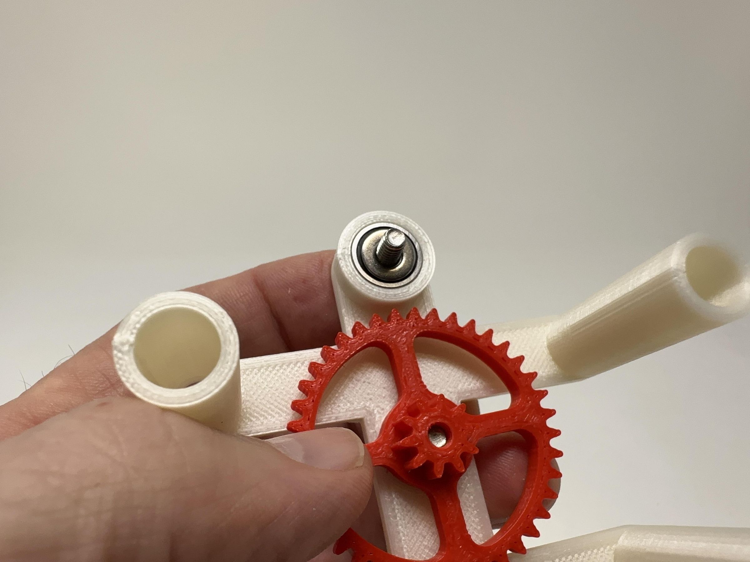
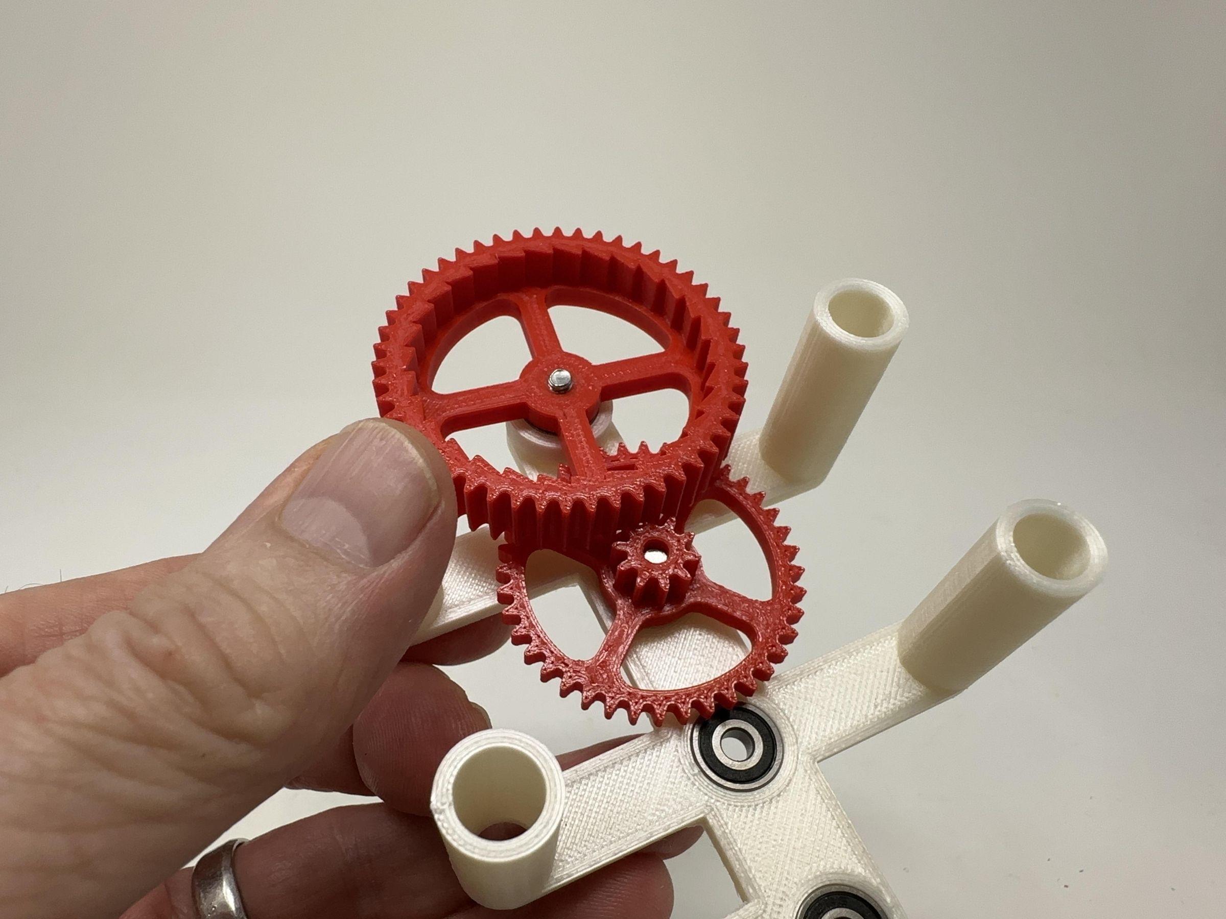
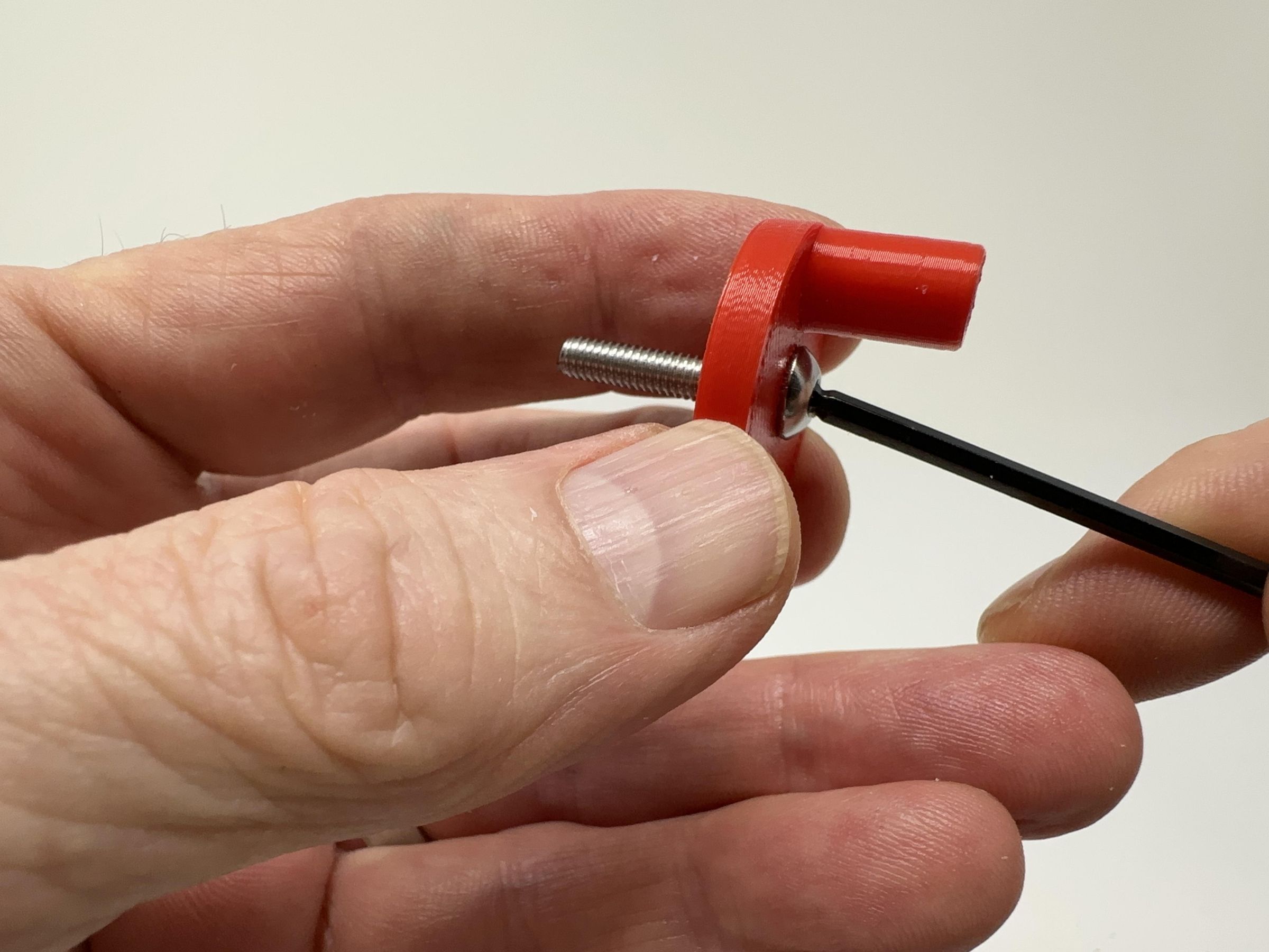
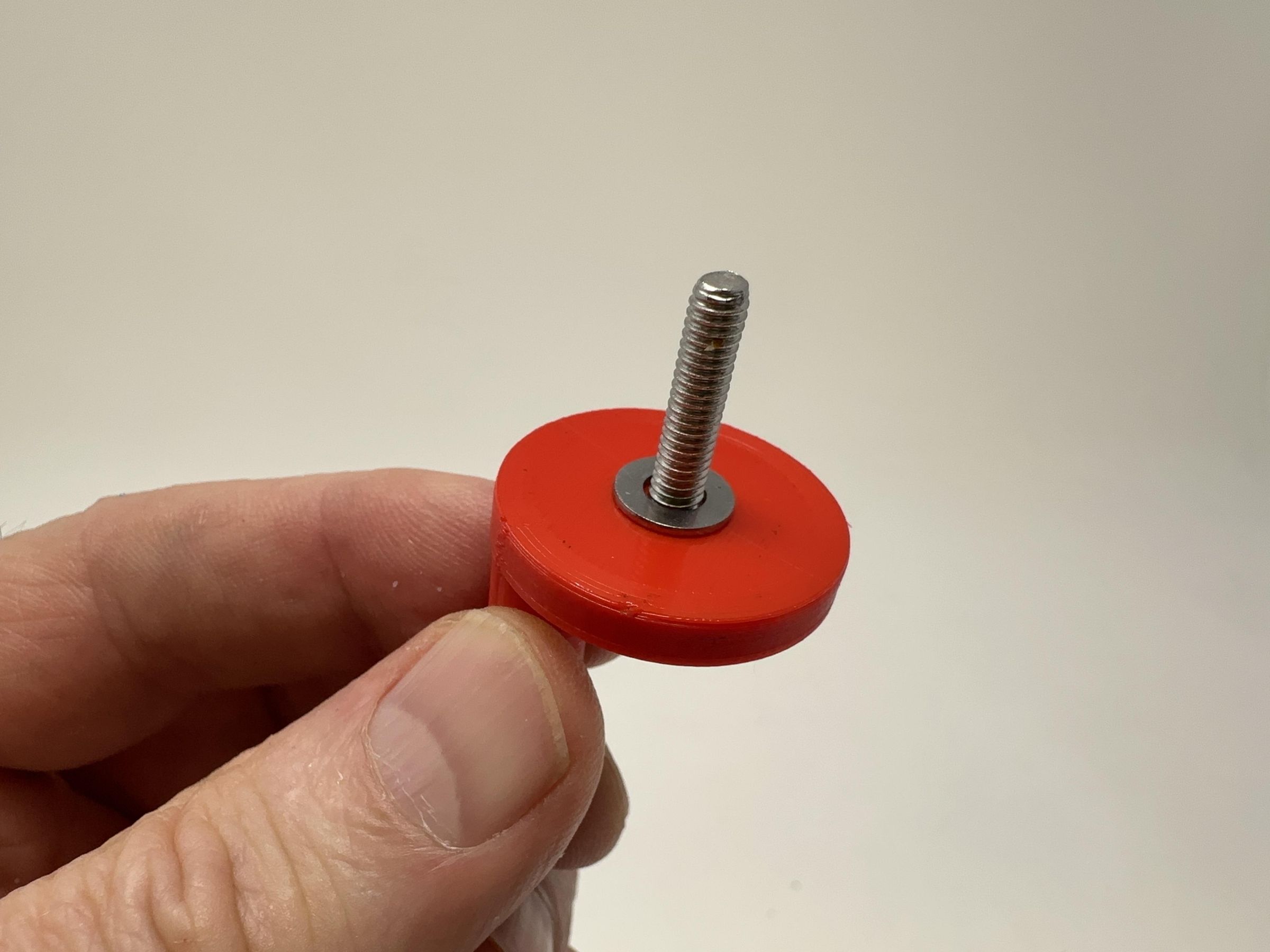
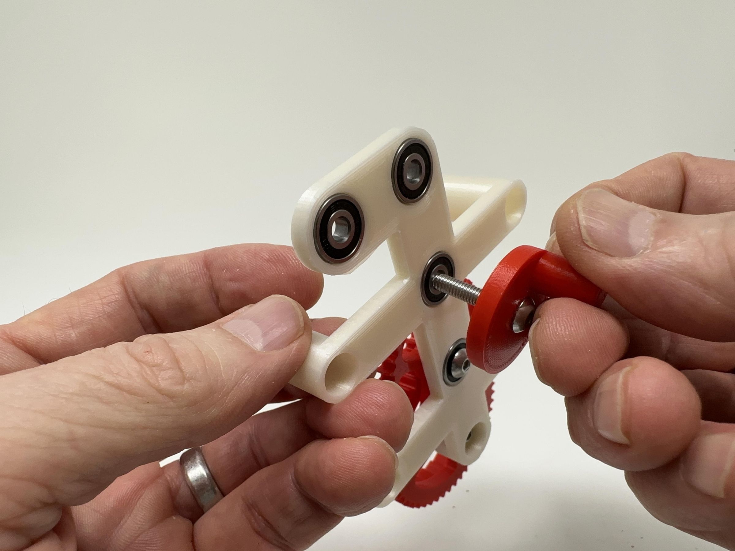
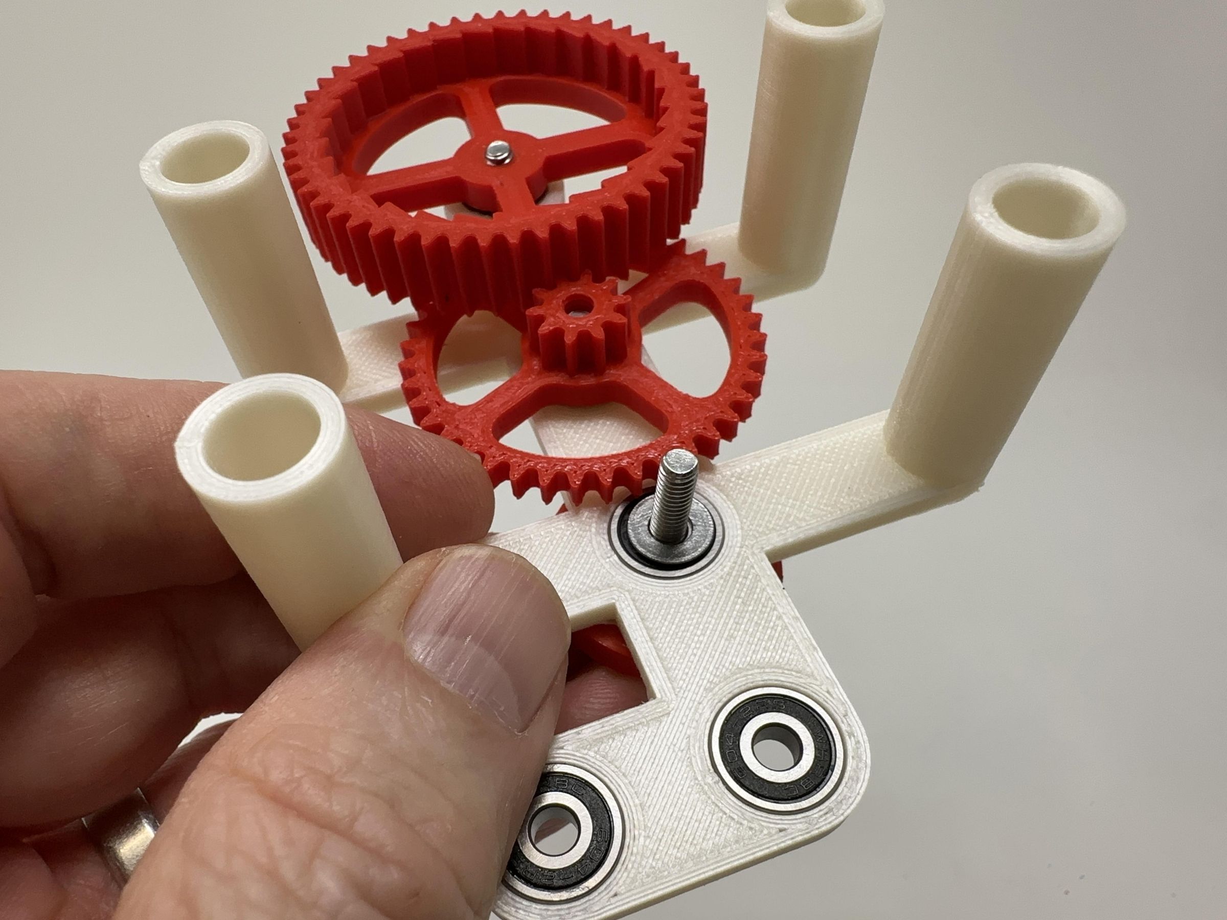
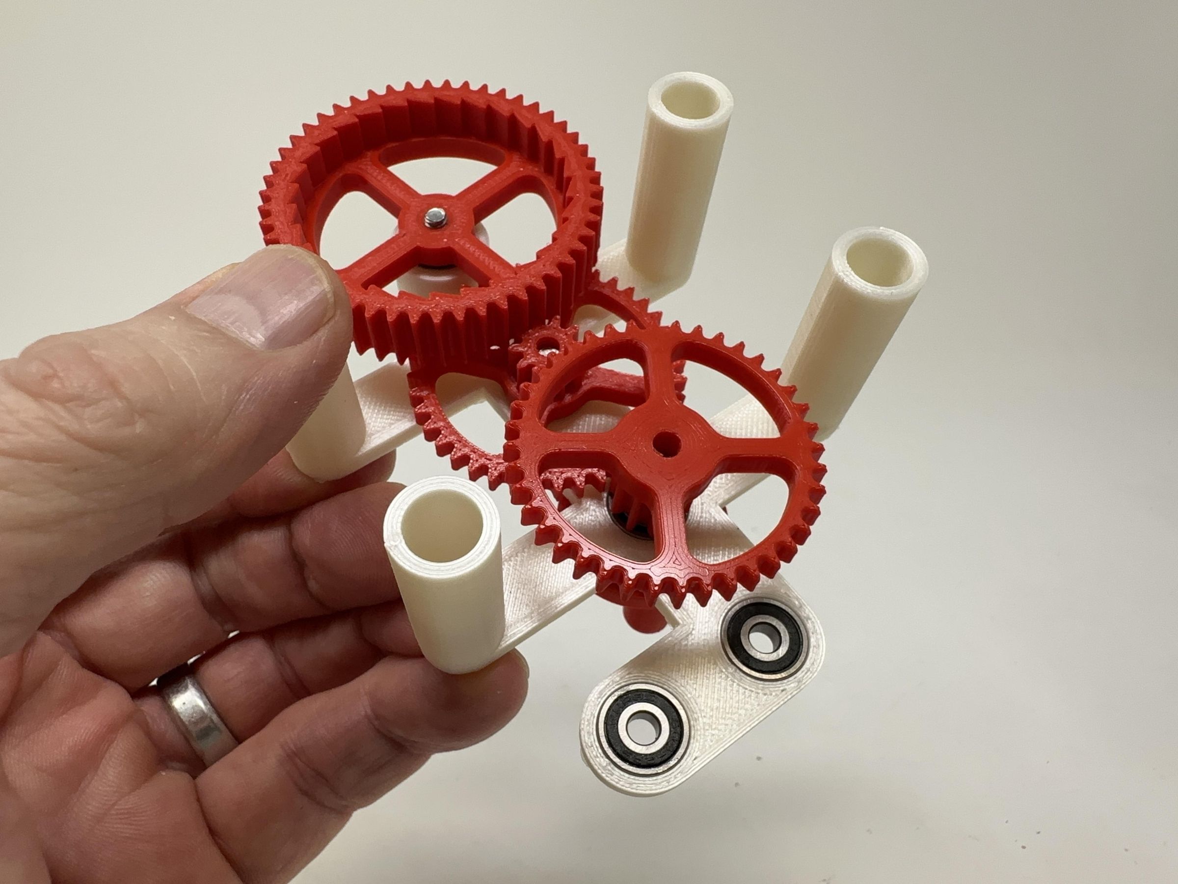
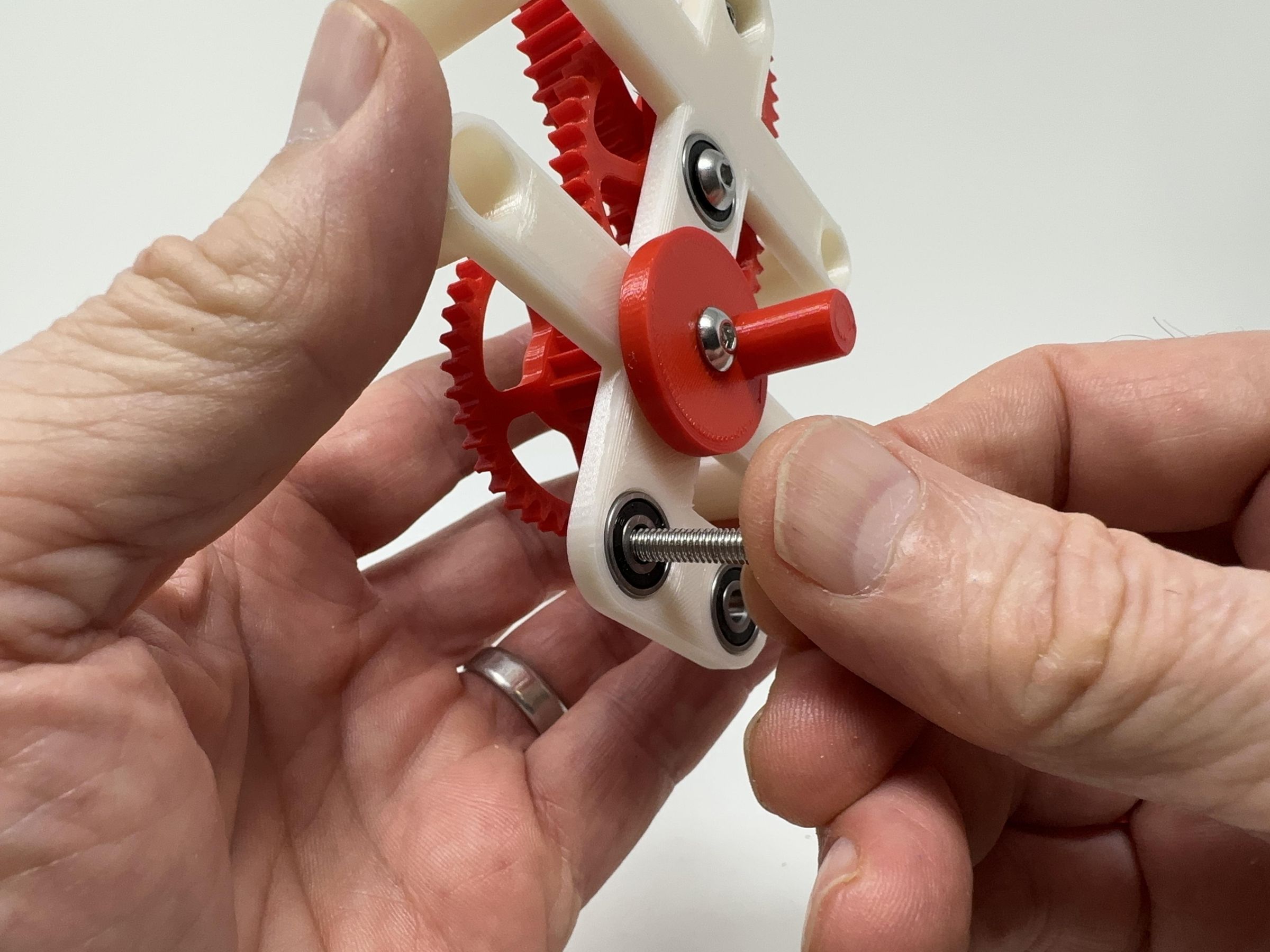
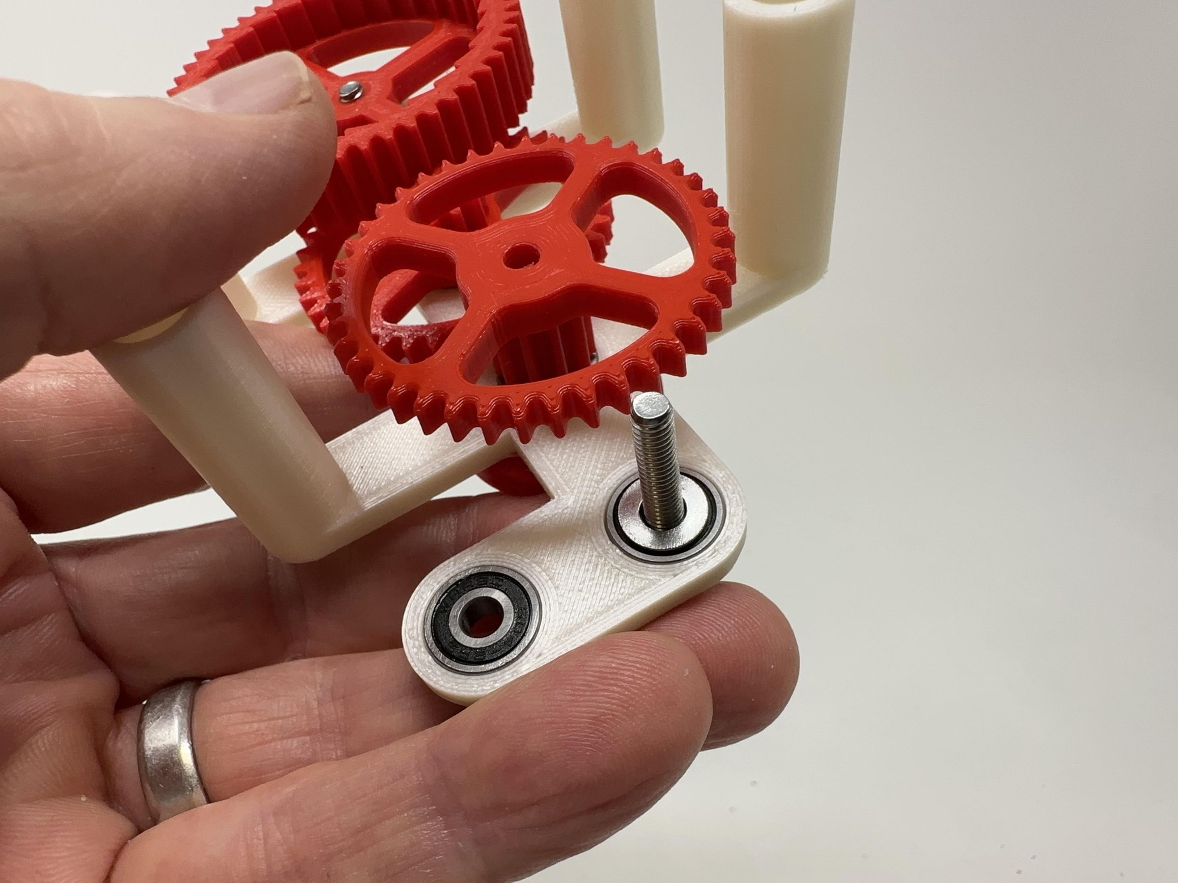
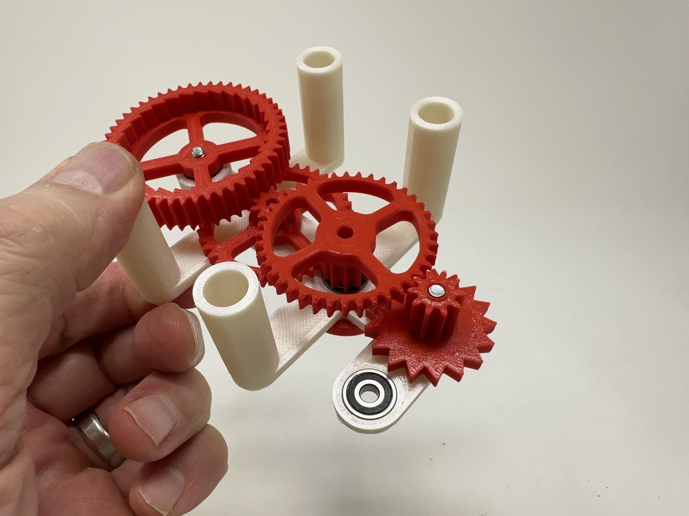
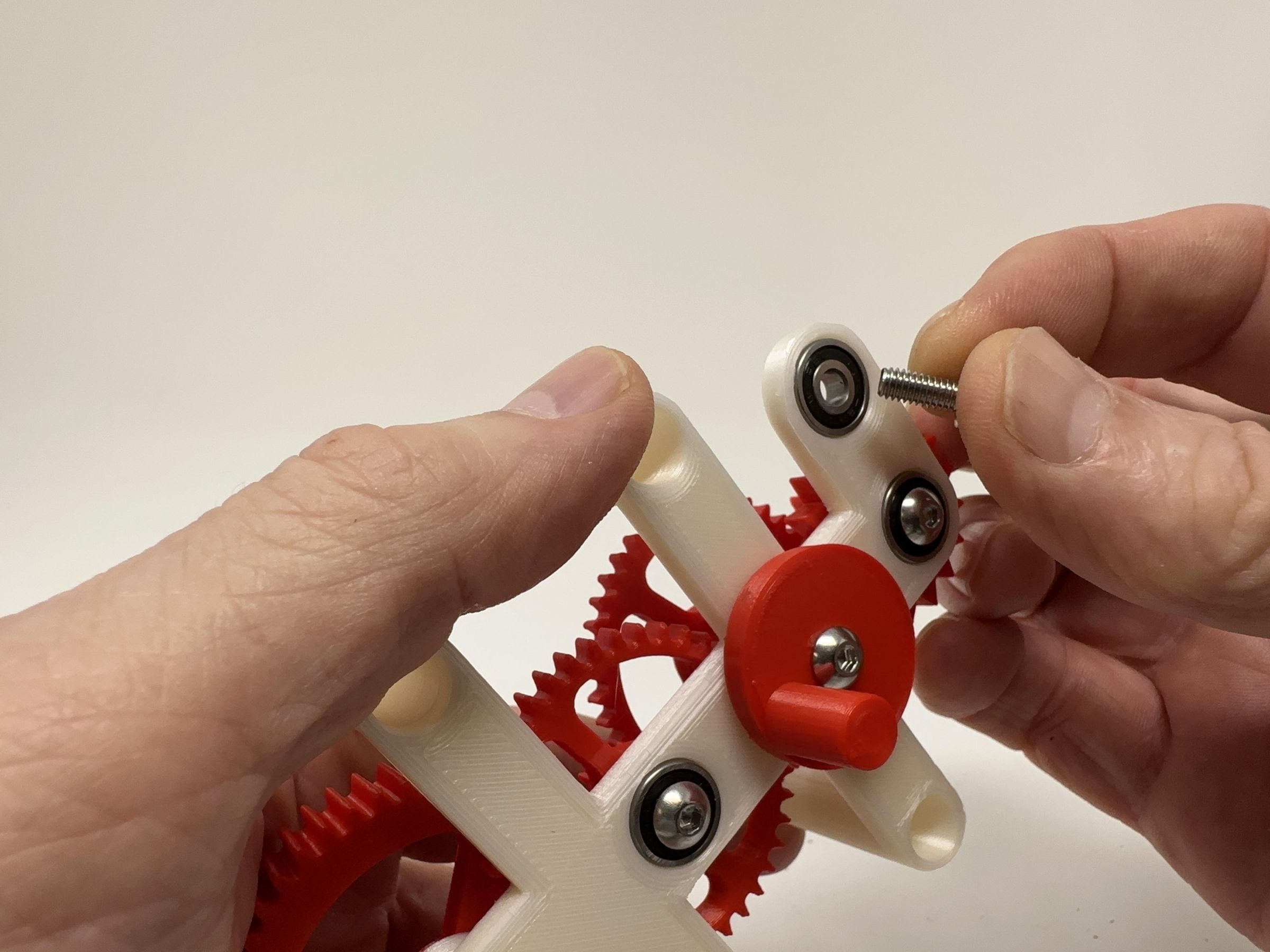
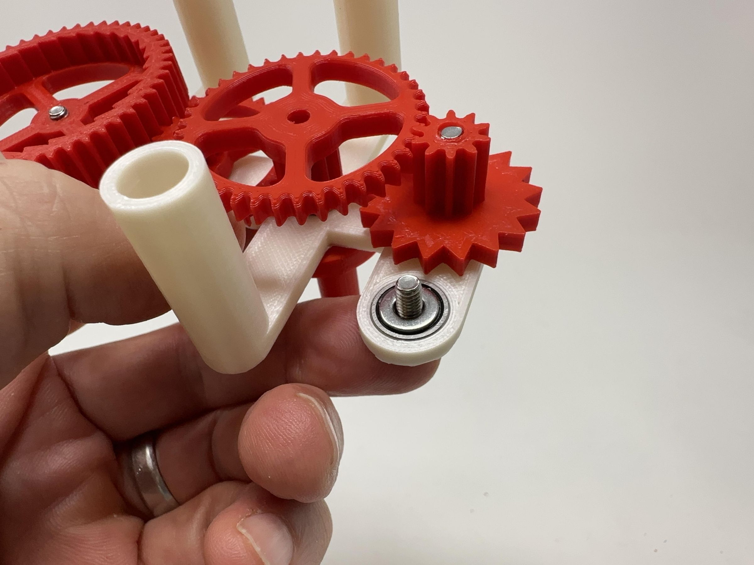
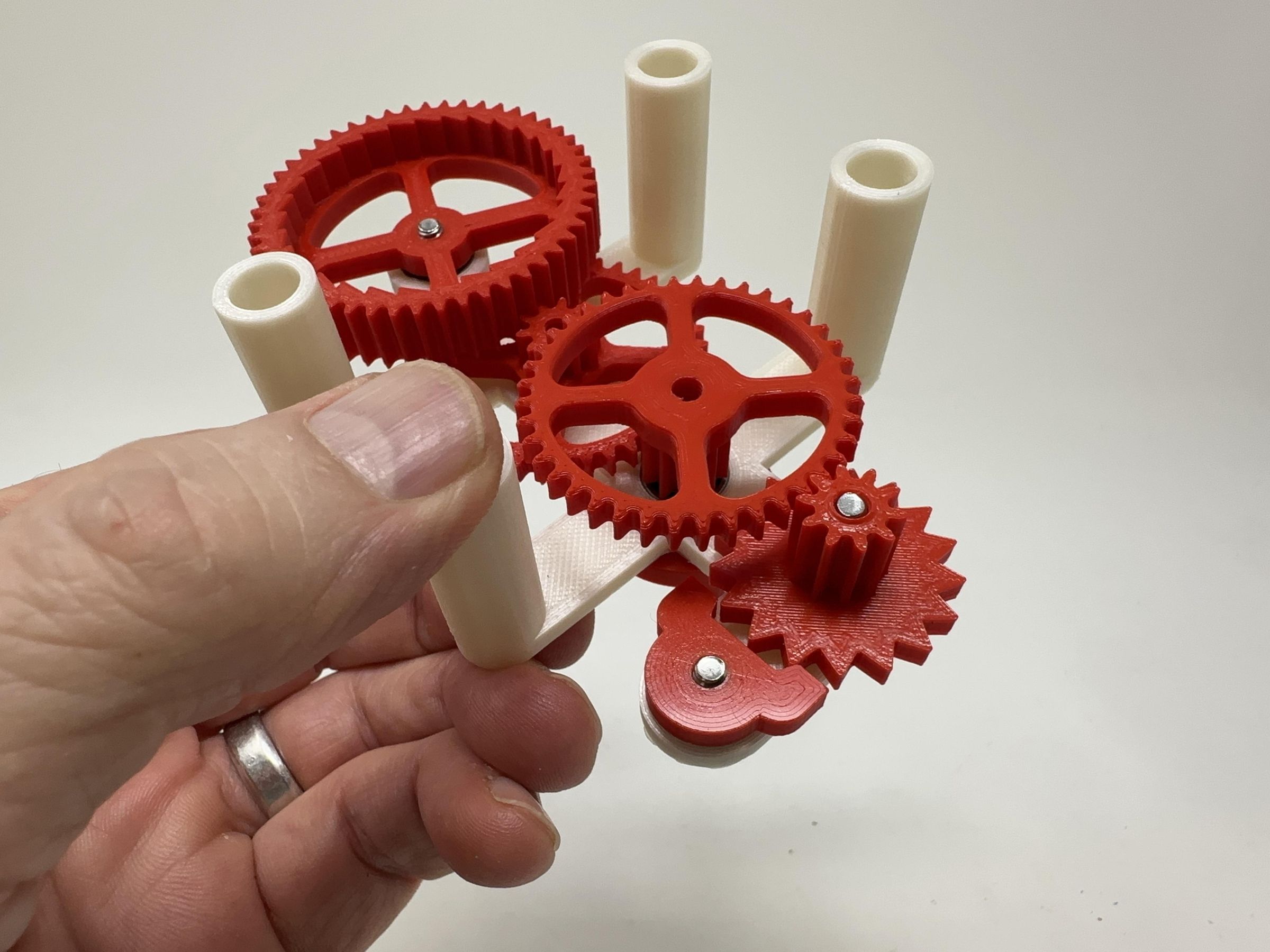
To assemble the gear plate, I performed the following steps:
- Pressed 5 deep groove ball bearings into "Gear Plate.stl" making absolutely certain that the bearing surfaces were flush with the gear plate. Small drops of glue may be required to secure the bearings in place.
- Placed one m4 by .7 by 12mm cap screw into the "Gear, Compound 1 (1m, 40t, 10t).stl" bearing.
- Placed one m4 washer over the cap screw threads.
- Threaded "Gear, Compound 1 (1m, 40t, 10t).stl" onto the cap screw threads making certain it rotated with ease.
- Placed one m4 by .7 by 12mm cap screw into the "Gear, Pawl (1m, 50t).stl" bearing.
- Placed one m4 washer over the cap screw threads.
- Threaded "Gear, Pawl (1m, 50t).stl" onto the cap screw threads making certain the gears rotated with ease.
- Threaded one m4 by .7 by 20mm cap screw into "Cam.stl".
- Placed one m4 washer over the cap screw threads.
- Placed the cam cap screw threads into the "Gear, Compound 2 (1m, 40t, 10t).stl" bearing.
- Placed one m4 washer over the cap screw threads.
- Threaded "Gear, Compound 2 (1m, 40t, 10t).stl" onto the cap screw threads making certain the gears rotated with ease.
- Placed one m4 by .7 by 20mm cap screw into the "Gear, Escapement, Compound (1m 10t).stl" bearing.
- Placed one m4 washer over the cap screw threads.
- Threaded "Gear, Escapement, Compound (1m 10t).stl" onto the cap screw threads making certain the gears rotated with ease.
- Placed one m4 by .7 by 10mm cap screw into the "Pallet.stl" bearing.
- Placed one m4 washer over the cap screw threads.
- Threaded "Pallet.stl" onto the cap screw threads making certain the gears rotated with ease.
Assemble the Base.
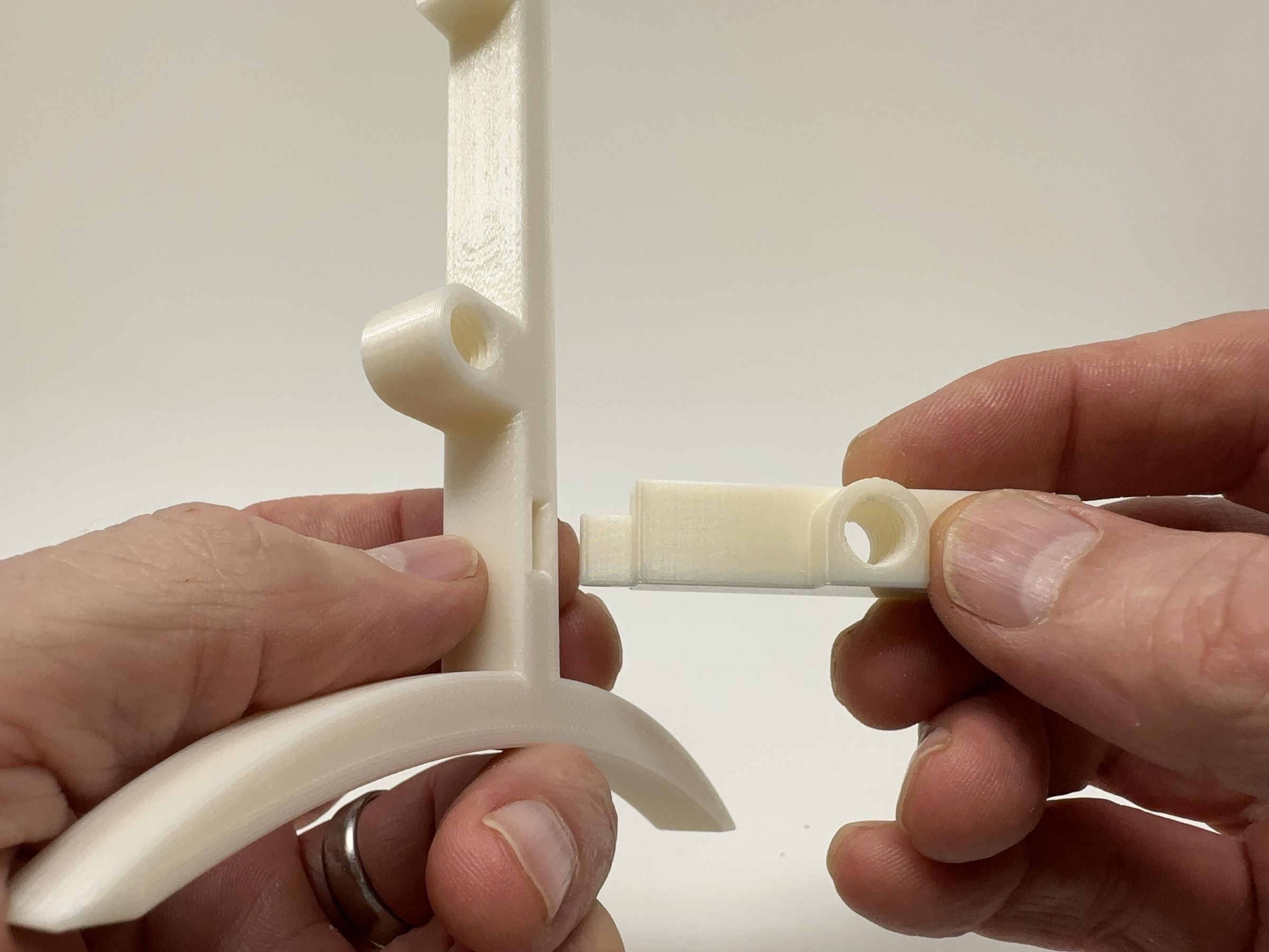
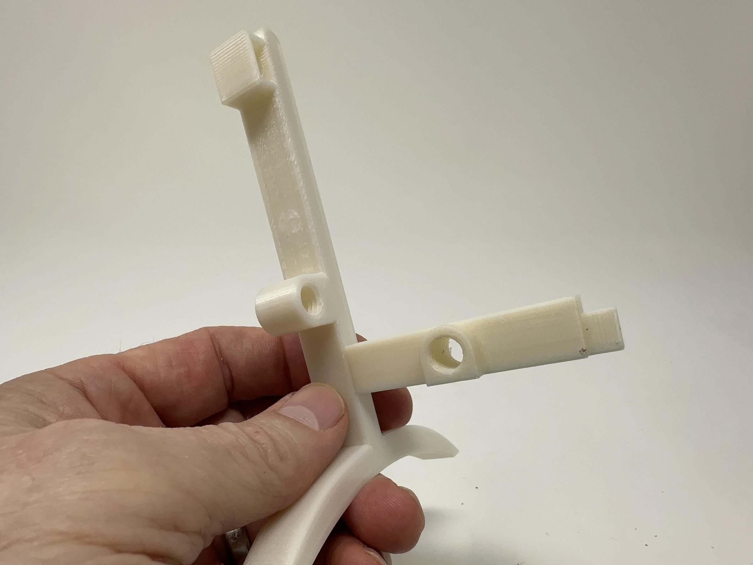
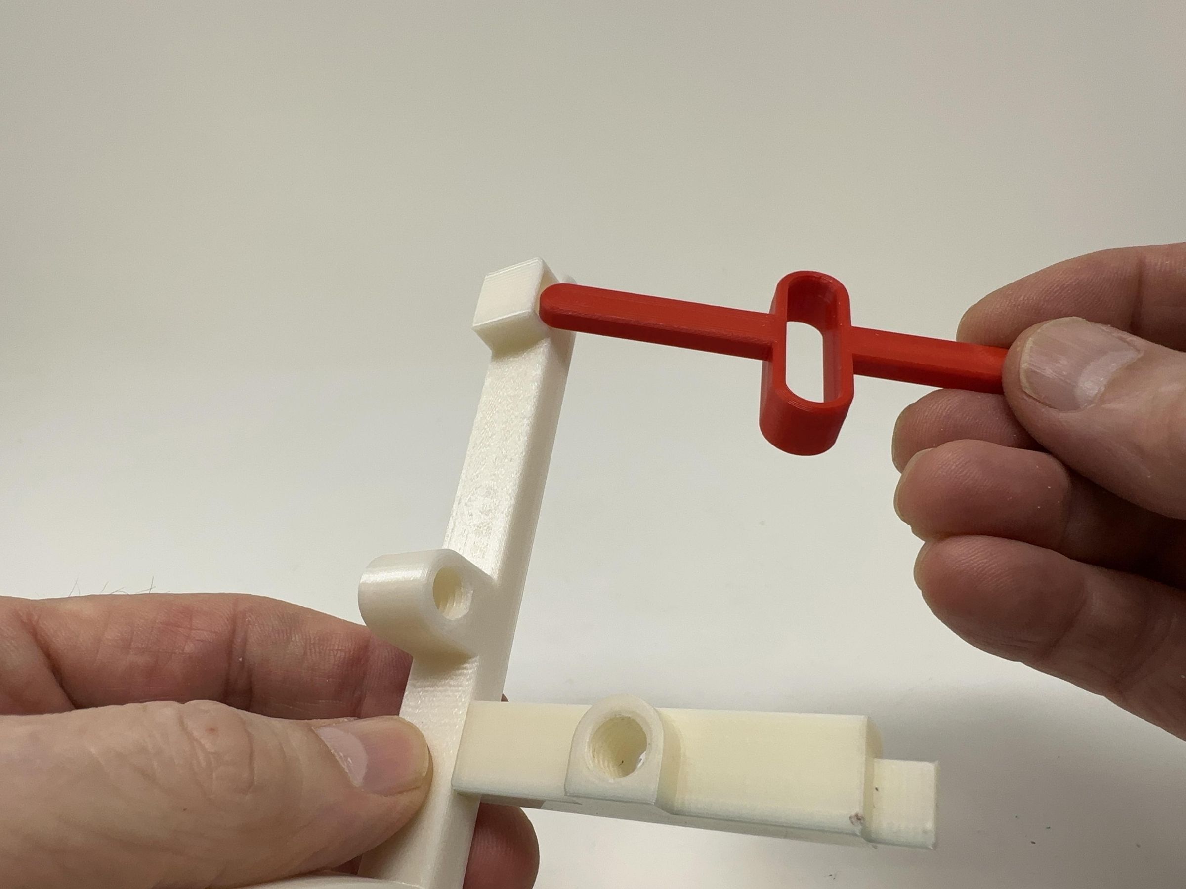
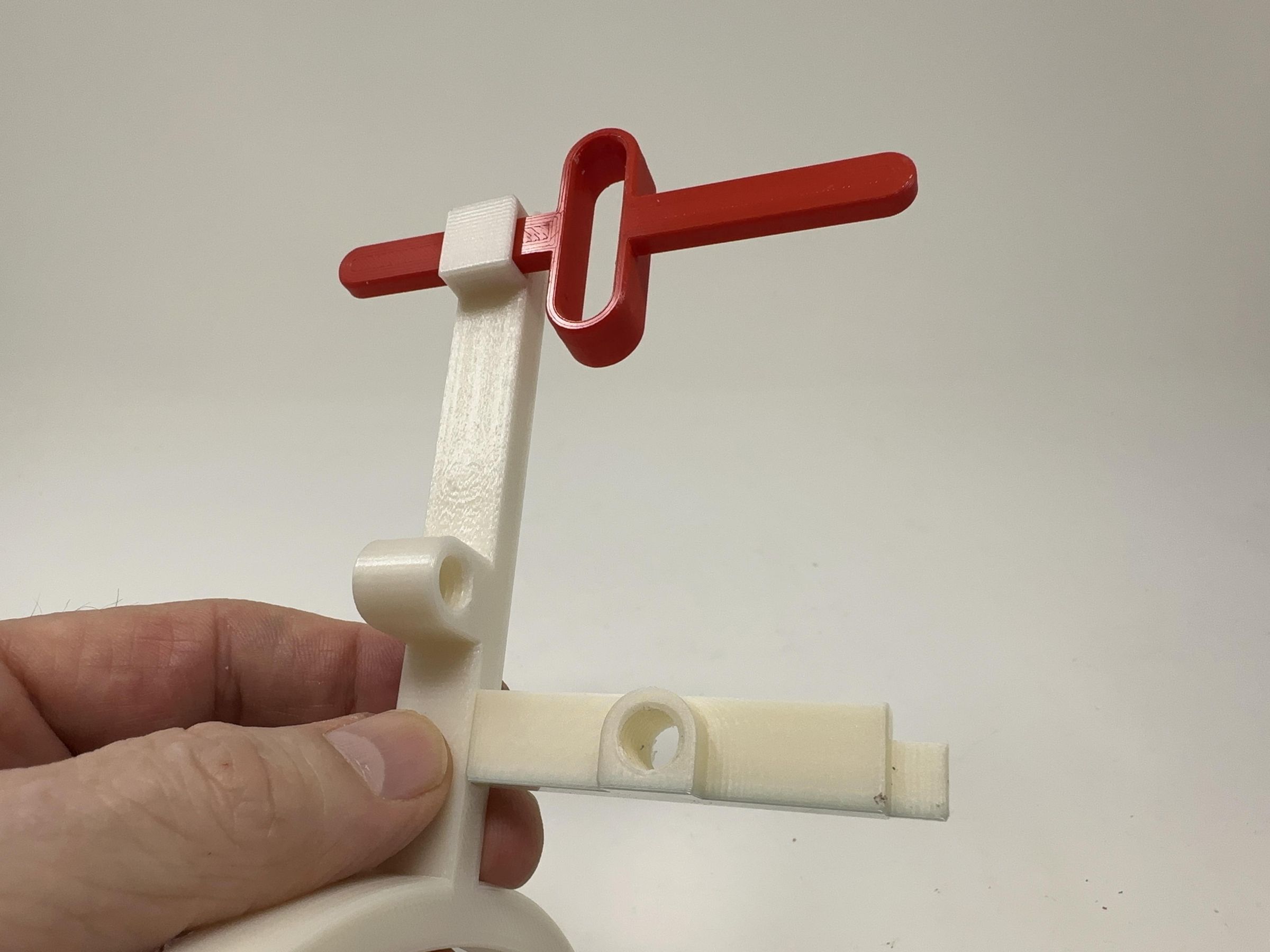
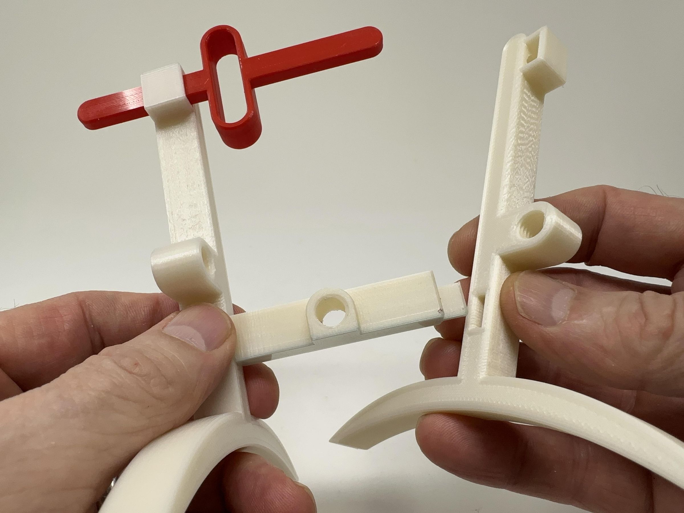
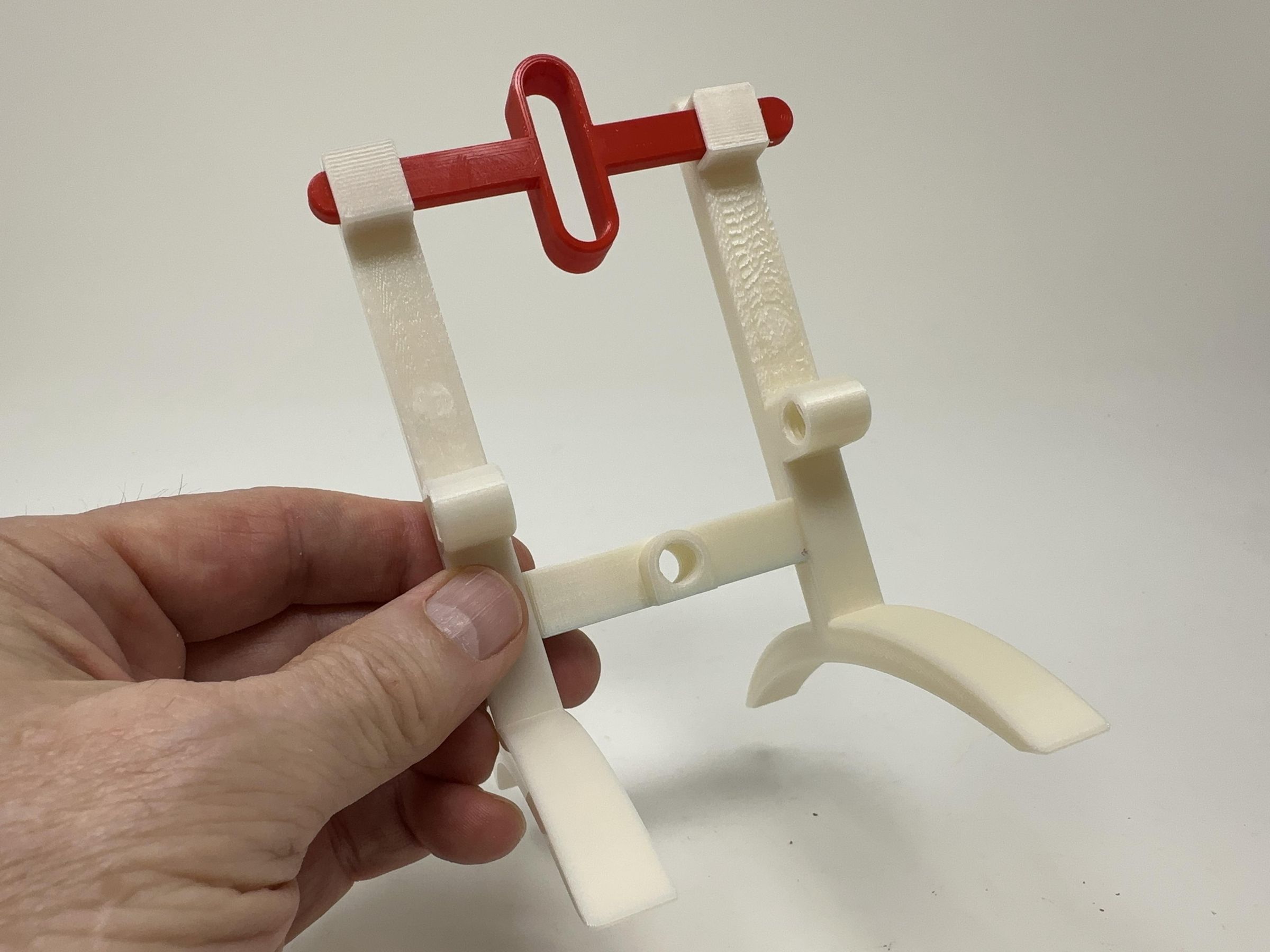
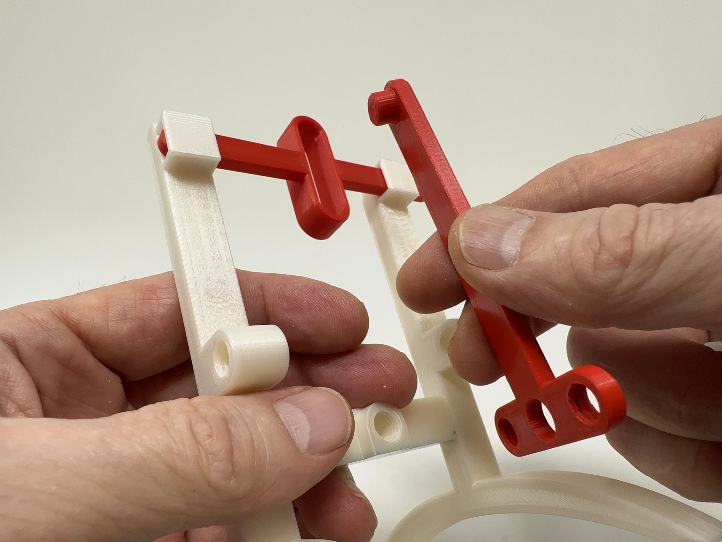
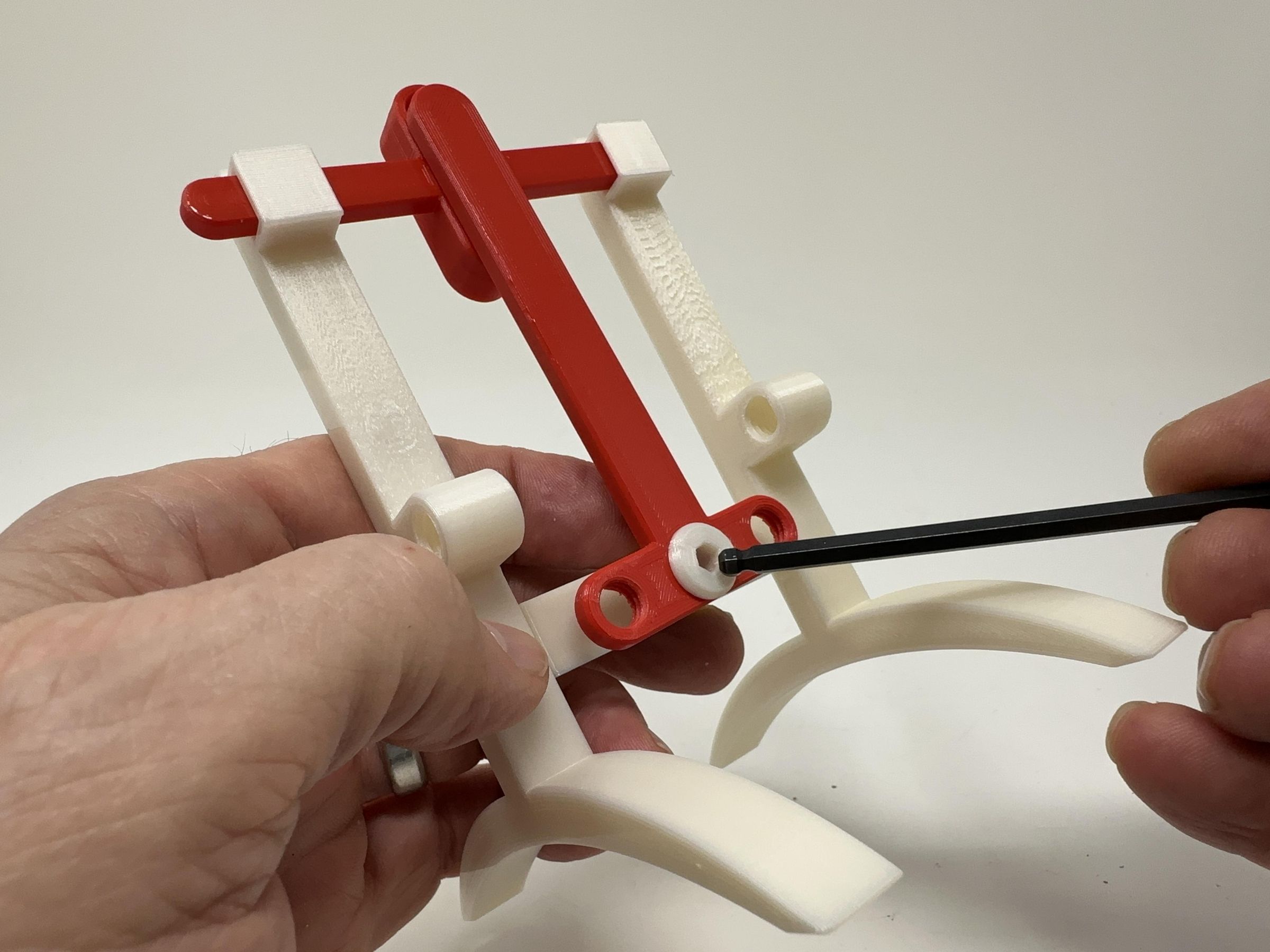
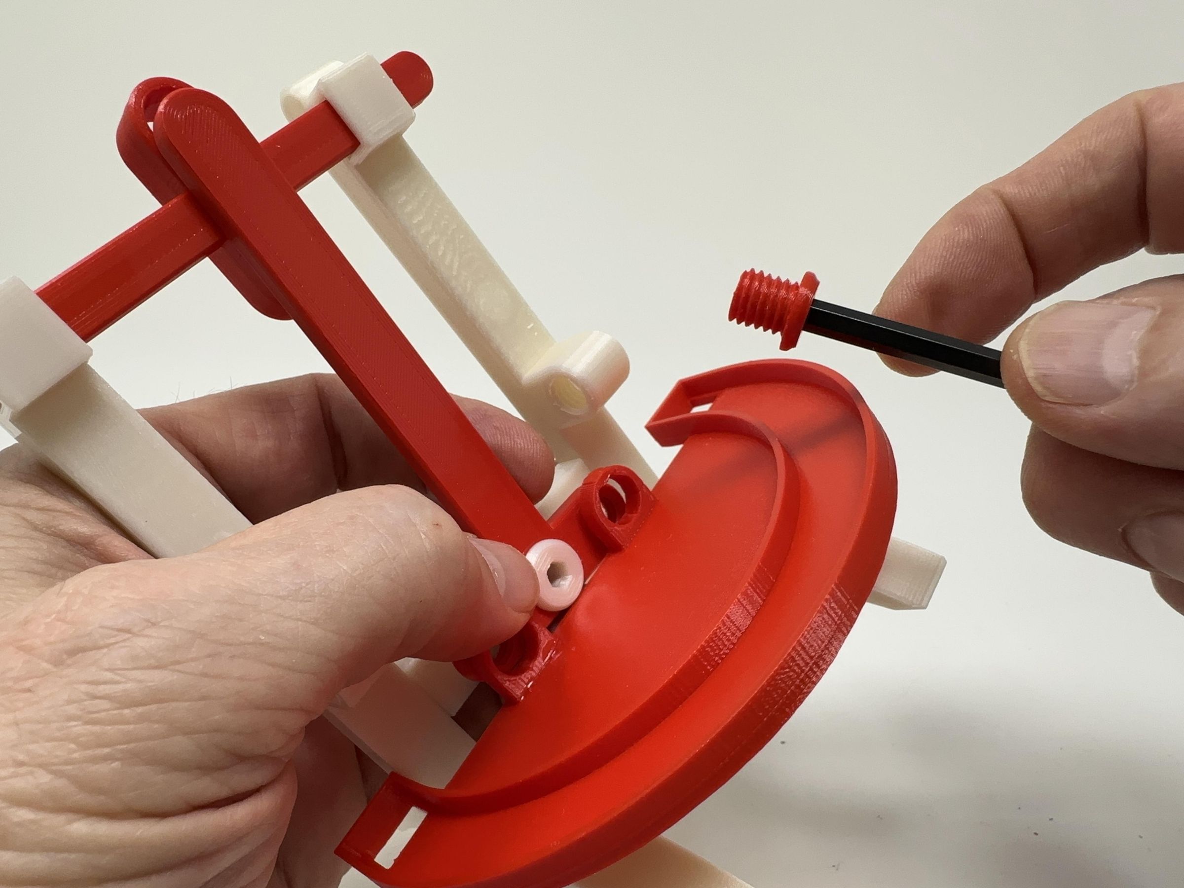
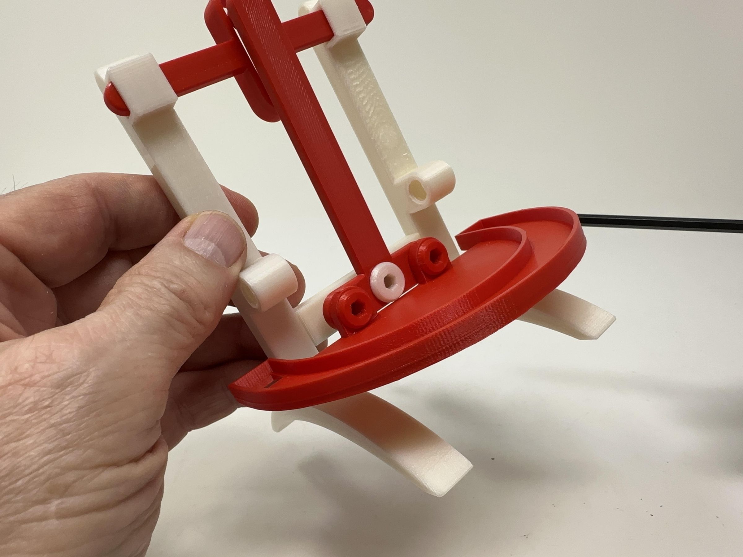
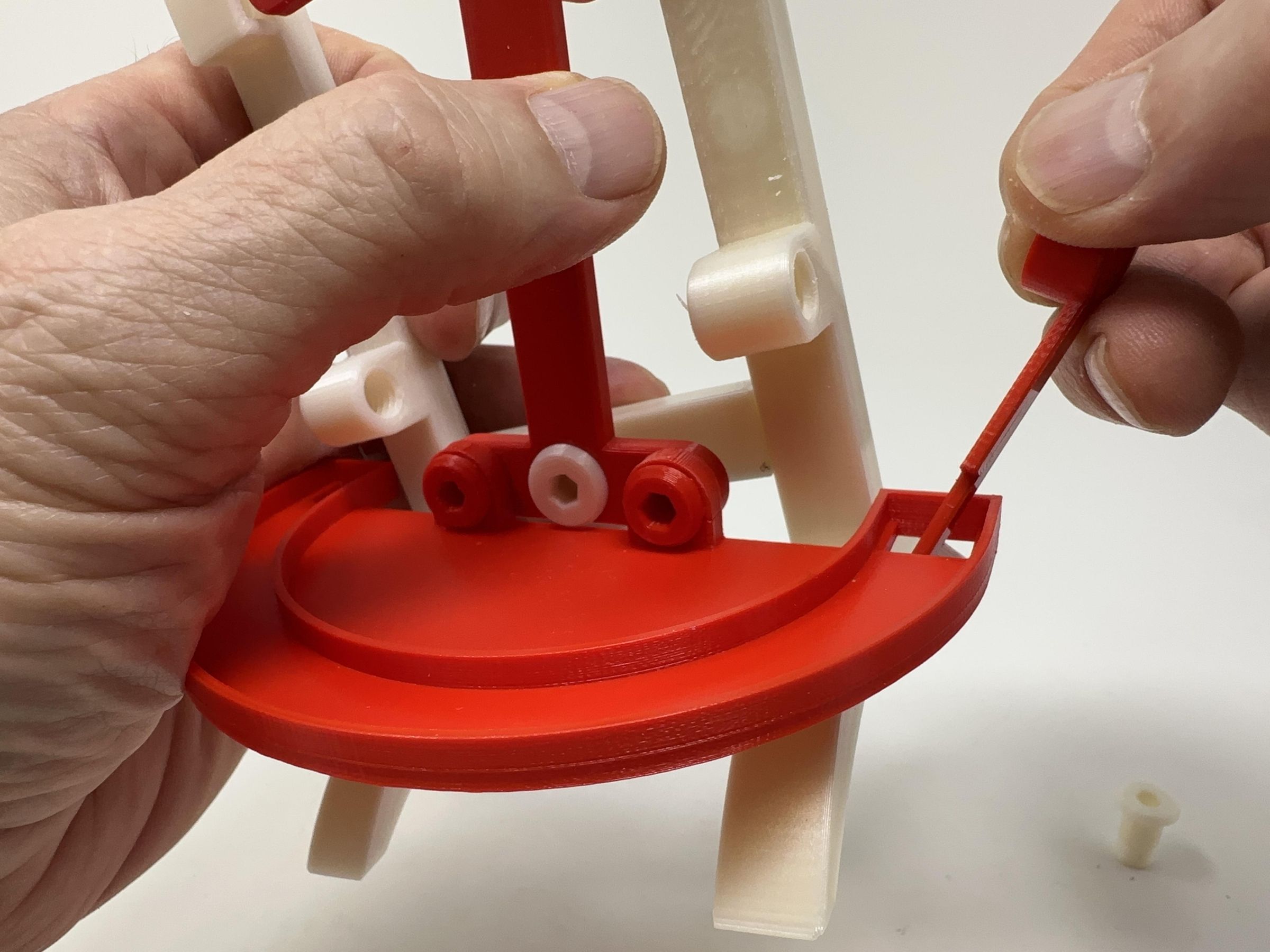
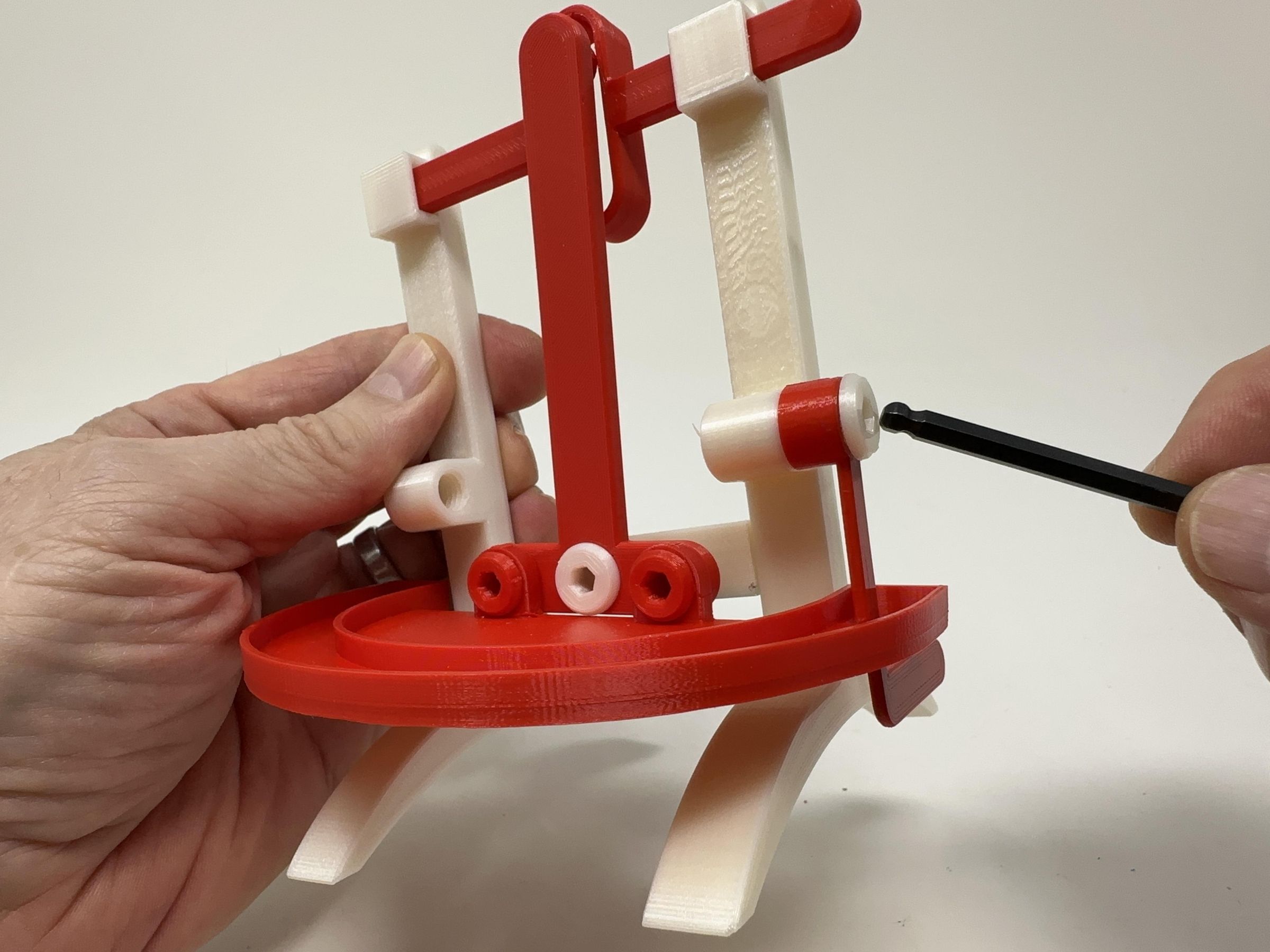
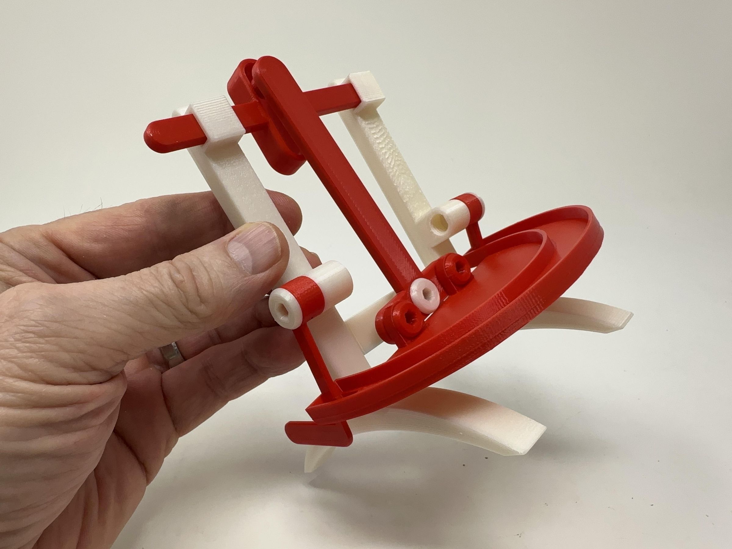
To assemble the base, I performed the following steps:
- Pressed "Base, Crossmember.stl" into the slot in "Base, Tower, Right.stl".
- Slid "Yoke.stl" into the yoke slot in the right tower assembly.
- Slid the free end of the yoke into the yoke slot in "Base, Tower, Left.stl", then pressed the left tower onto the crossmember.
- Placed the pin on "Arm, Rocker.stl" into the yoke slot, then attached the rocker to the base crossmember using one "Axle, Arm, Rocker.stl" making certain the mechanism moved with ease.
- Attached "Track.stl" to the rocker using two "Bolt (M8 by 1.25 by 8).stl".
- Slid the bladed end of "Arm, Release, Left.stl" into the left hole in the track then attached to left release arm to the base assembly using one "Axle, Arm, Release.stl" making certain the arm rotated with ease.
- Repeated the previous step with "Arm, Release, Right.stl" and "Axle, Arm, Release.stl" in the right hole in the track.
Final Assembly.

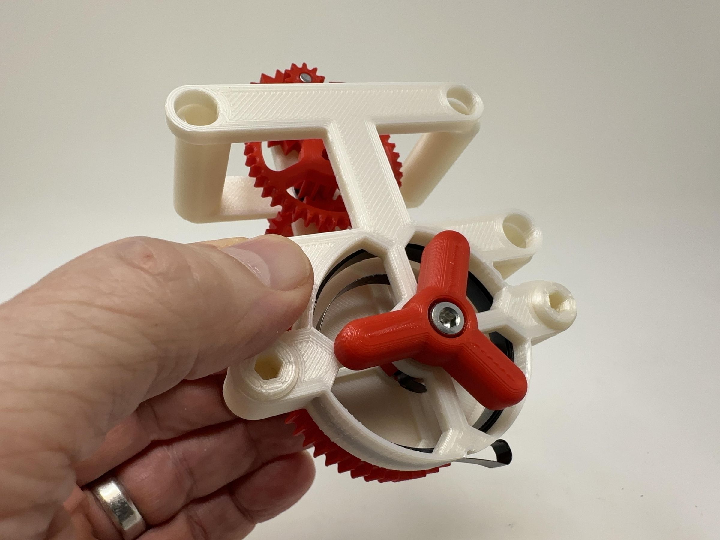
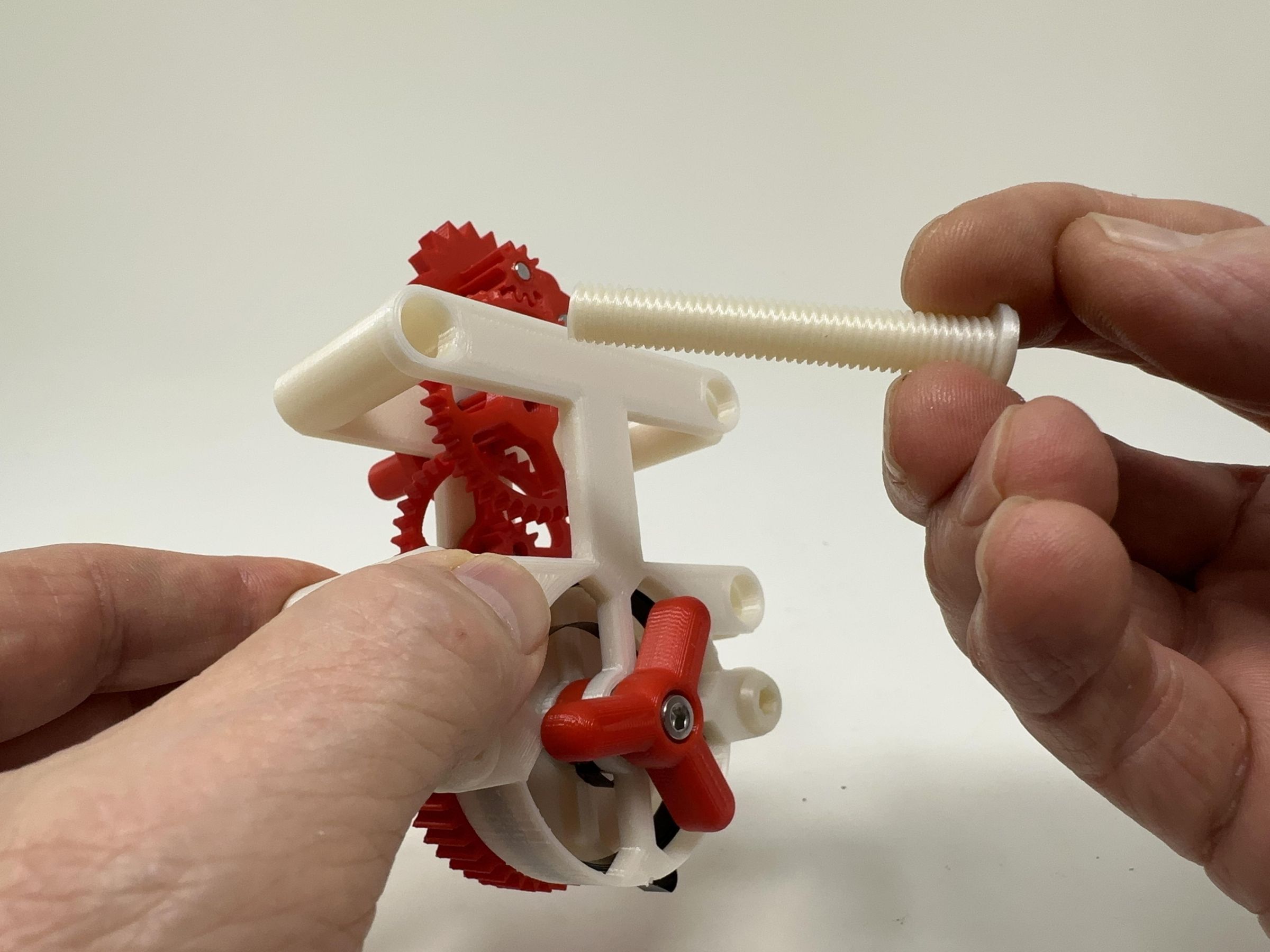
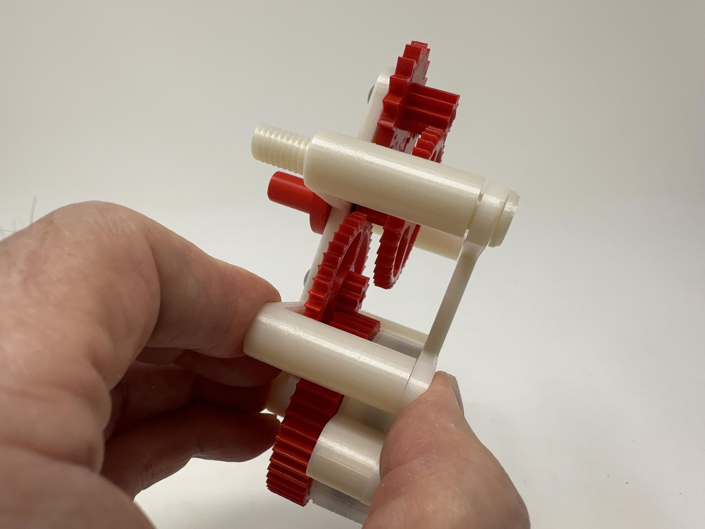
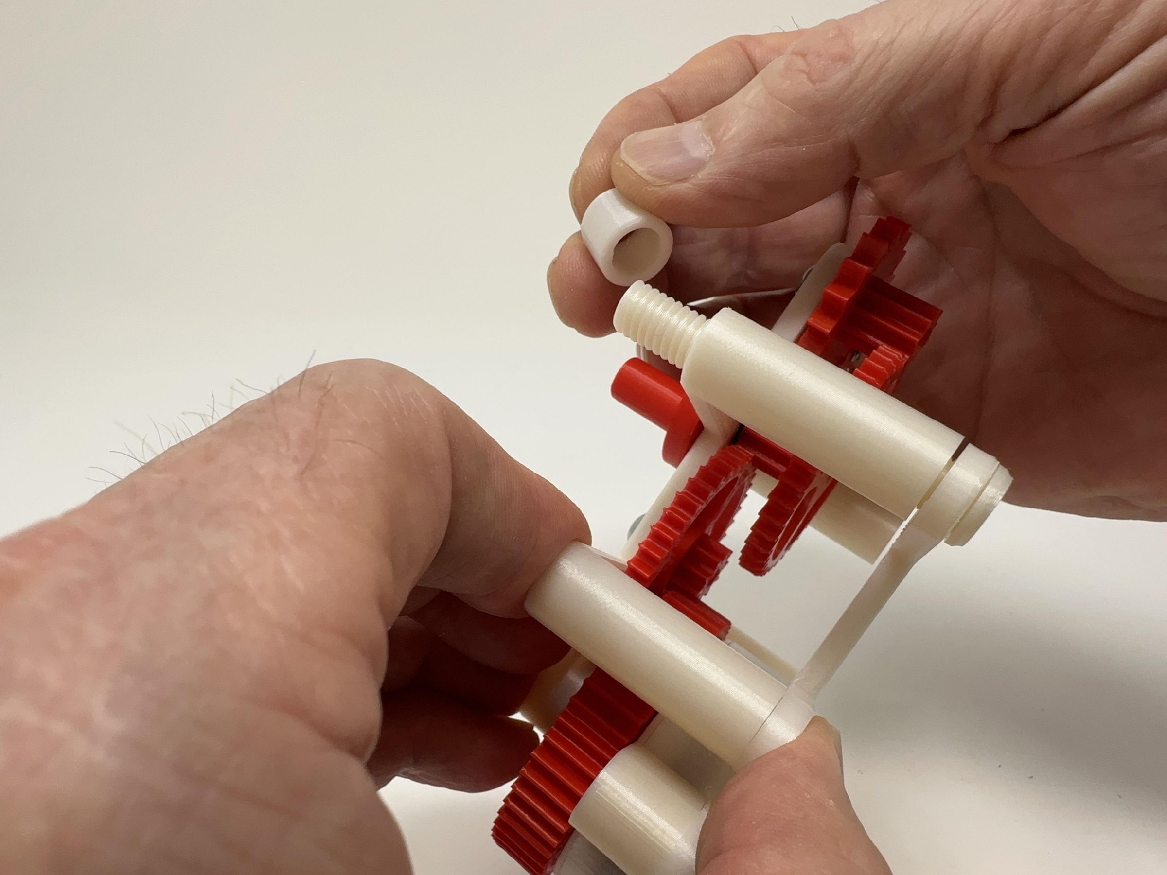
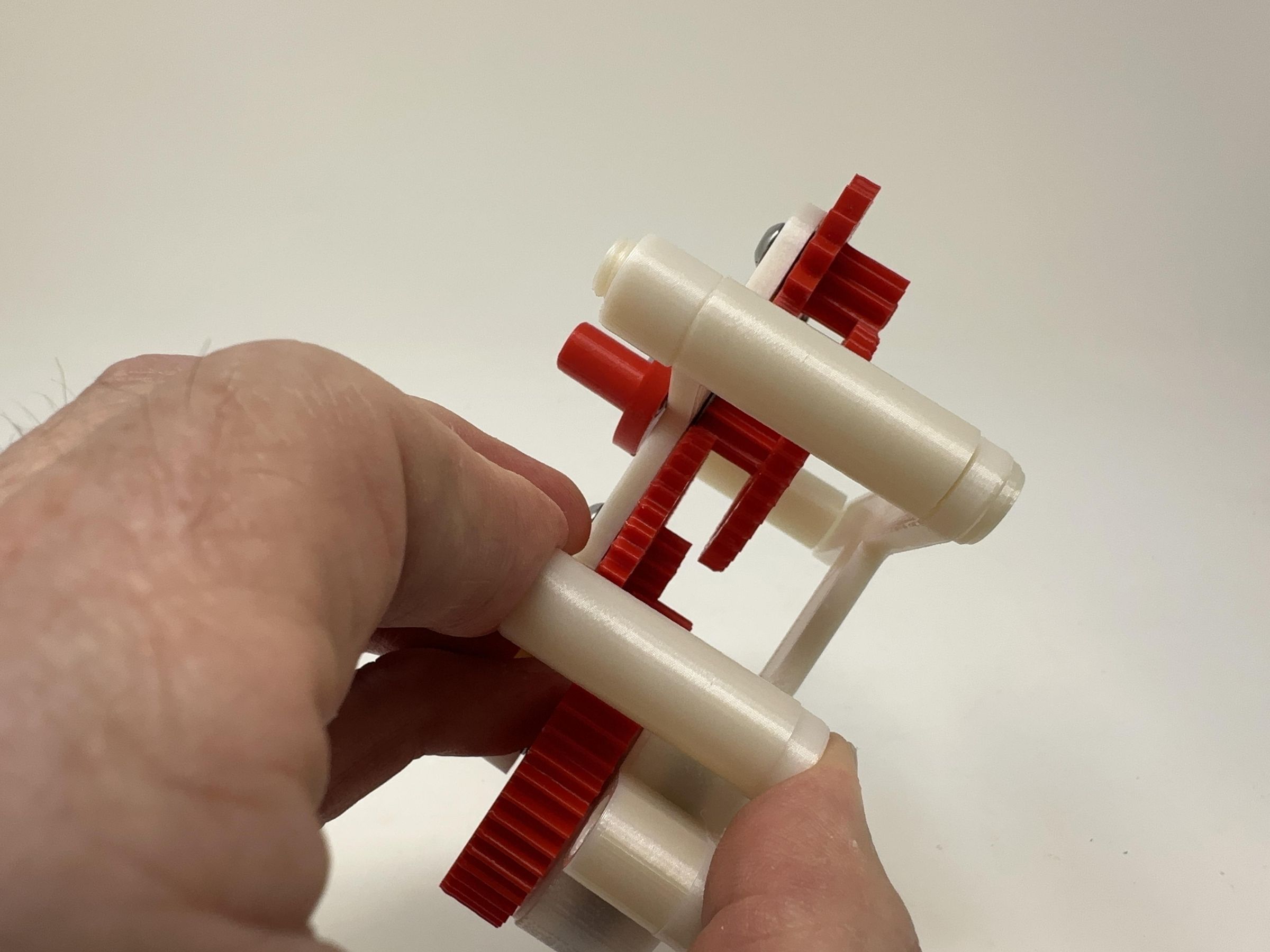
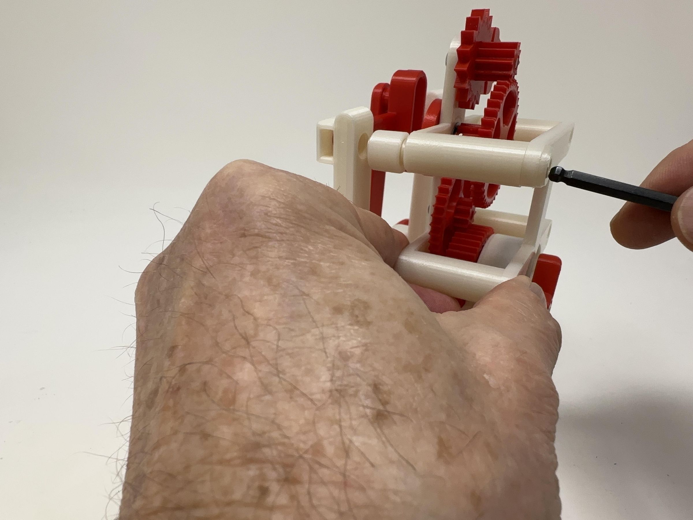
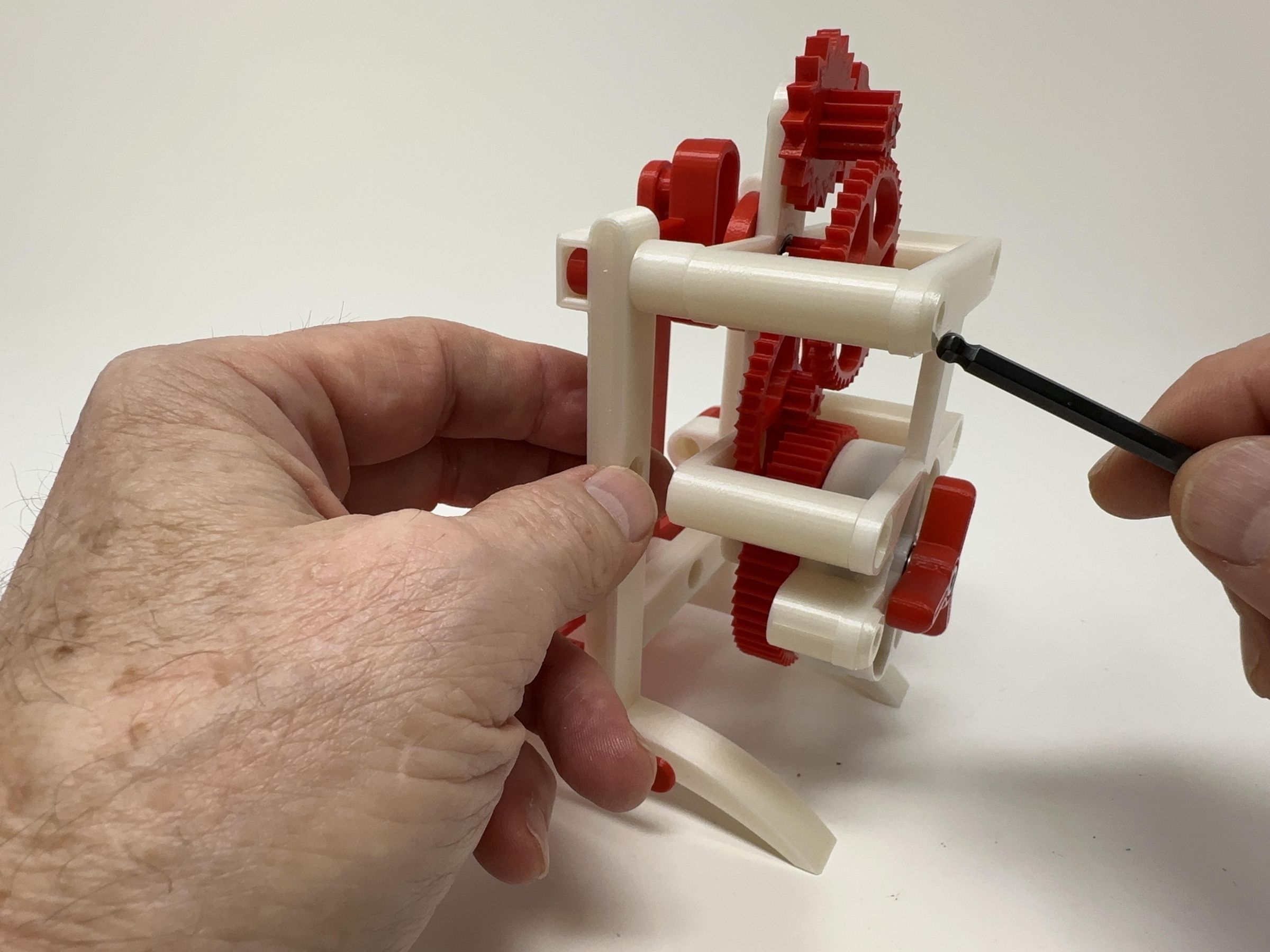
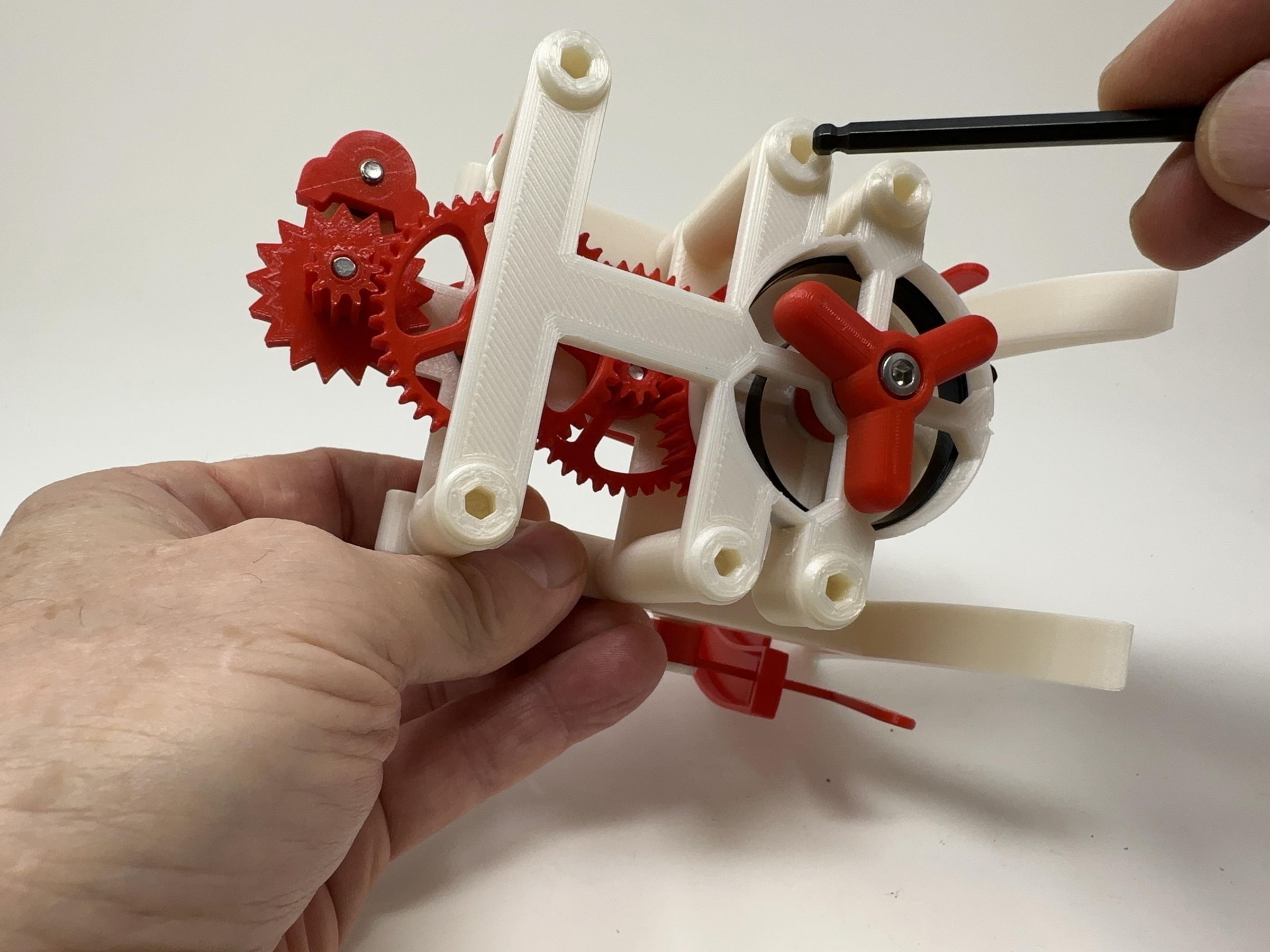
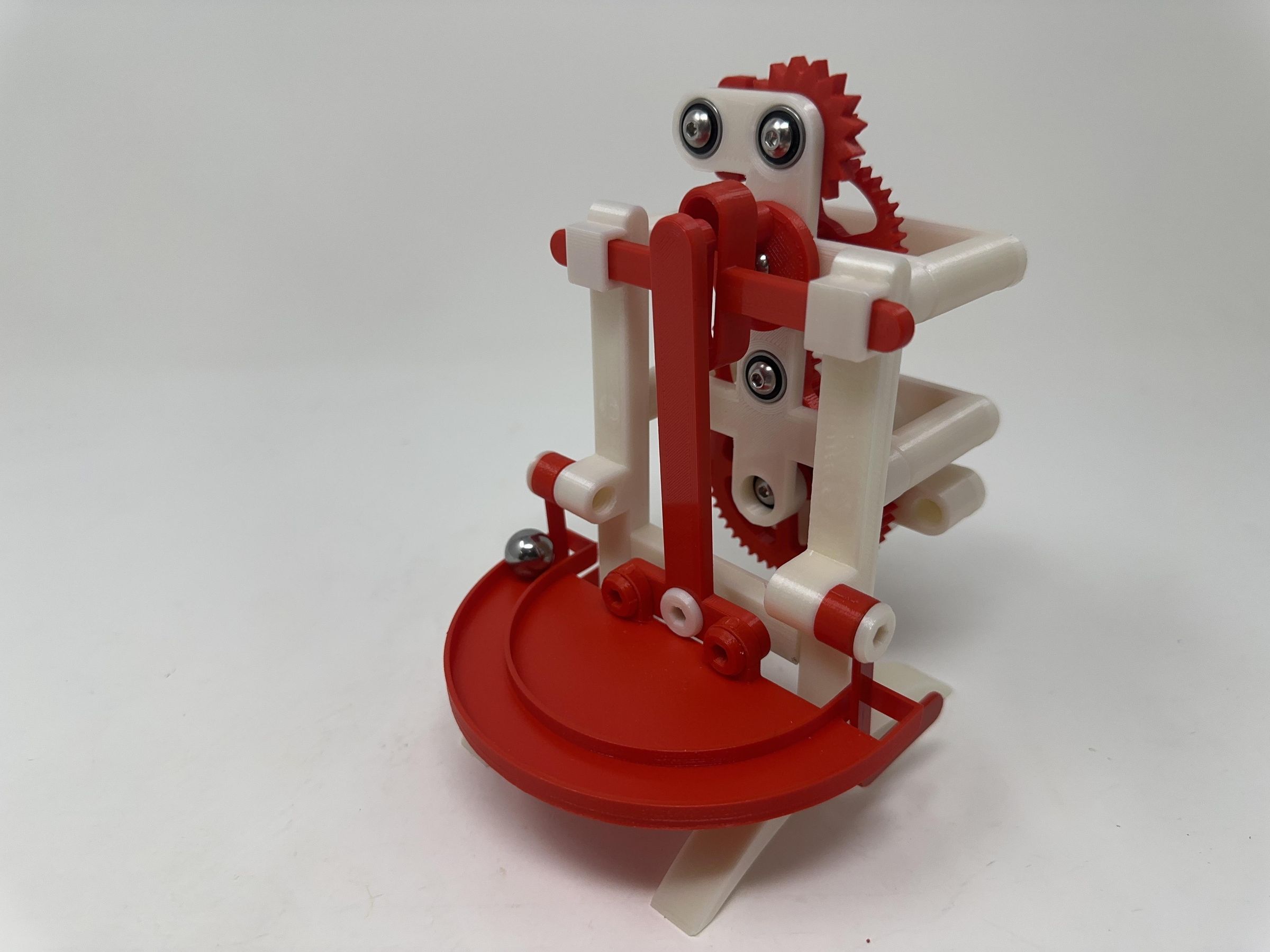
For final assembly, I performed the following steps:
- Positioned the spring housing assembly over the gear plate assembly while sliding the pawl into the pawl gear.
- Slid one "Bolt (M8 by 1.25 by 50).stl" through the upper left hole in the spring housing assembly then through the upper left hole of the gear plate assembly.
- Slid one "Spacer (10mm).stl" onto the exposed end of the bolt.
- Threaded the bolt into the base assembly.
- Installed the remaining three bolts and spacers.
With assembly complete, I carefully wound the spring, placed the model on a level surface, placed the .5" ball bearing on the elevated end of the track and let it go!
And that is how I 3D printed and assembled "Rolling Ball Oscillator".
I hope you enjoyed it!