SIGNAL: Pocket Off-Grid Morse Pacer & Emergency Beacon
by The Uncertified Engineer in Outside > Survival
110 Views, 3 Favorites, 0 Comments
SIGNAL: Pocket Off-Grid Morse Pacer & Emergency Beacon
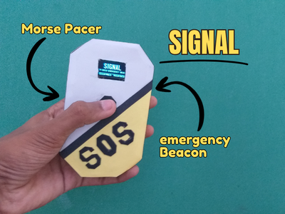
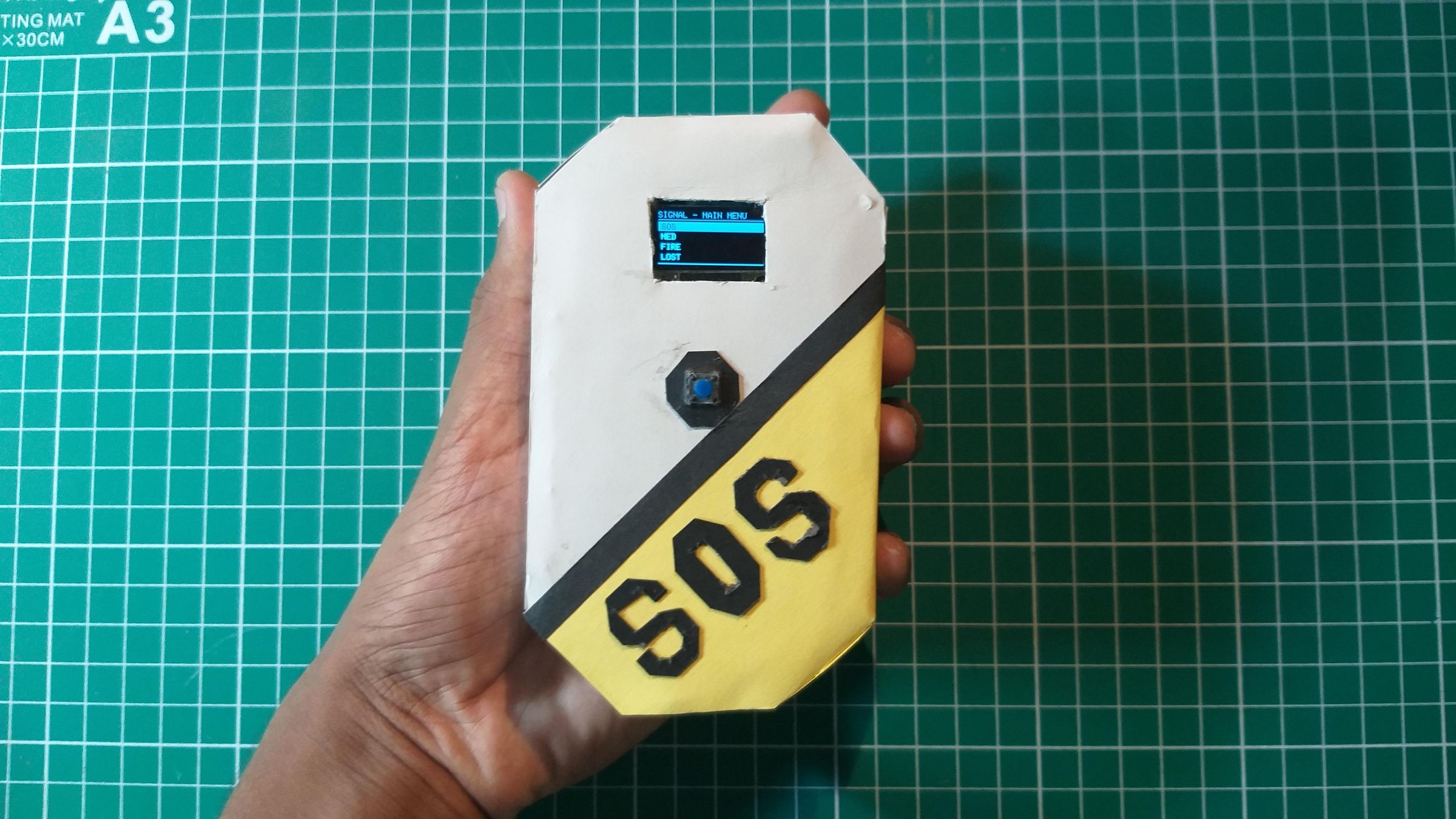
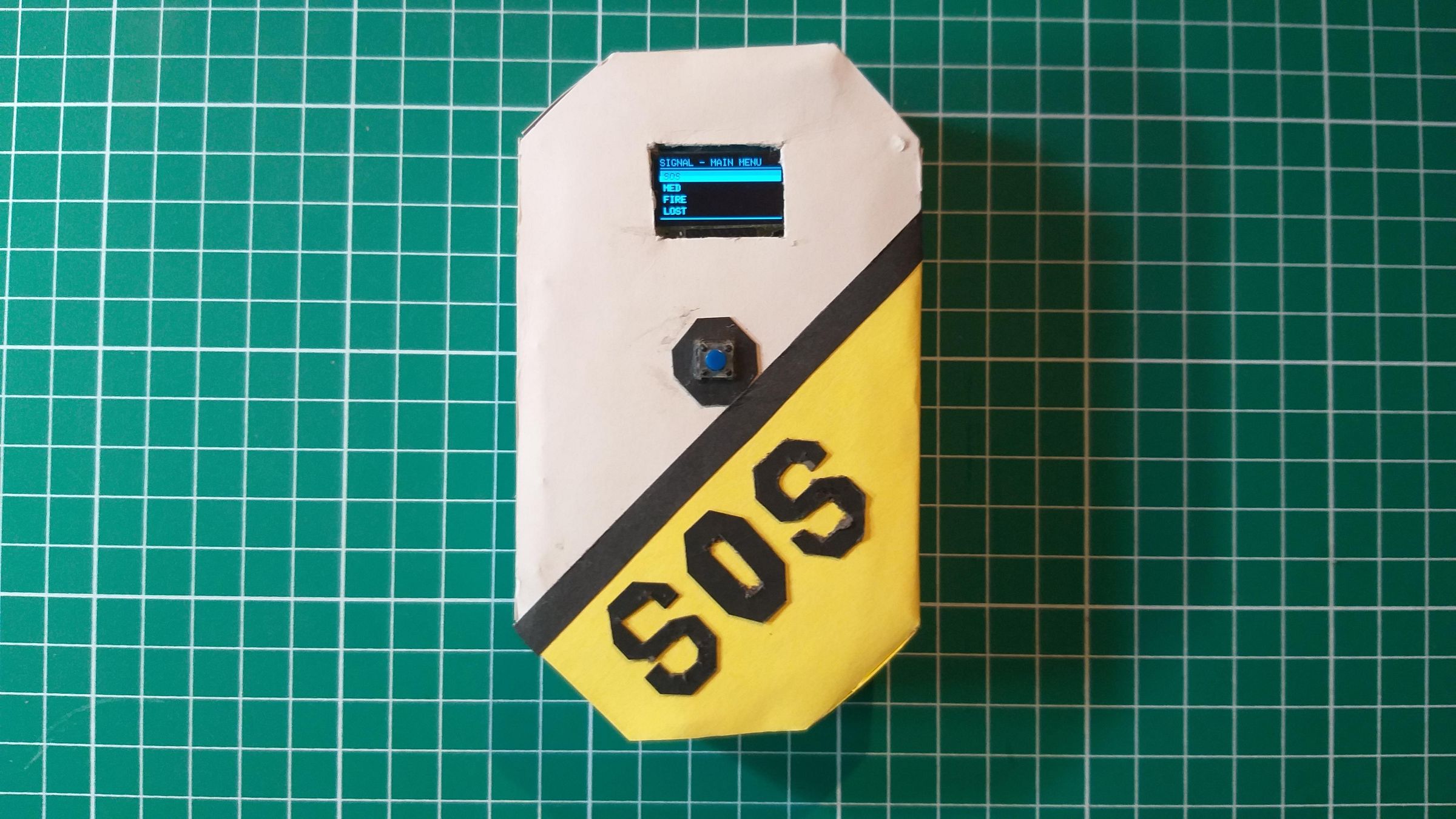
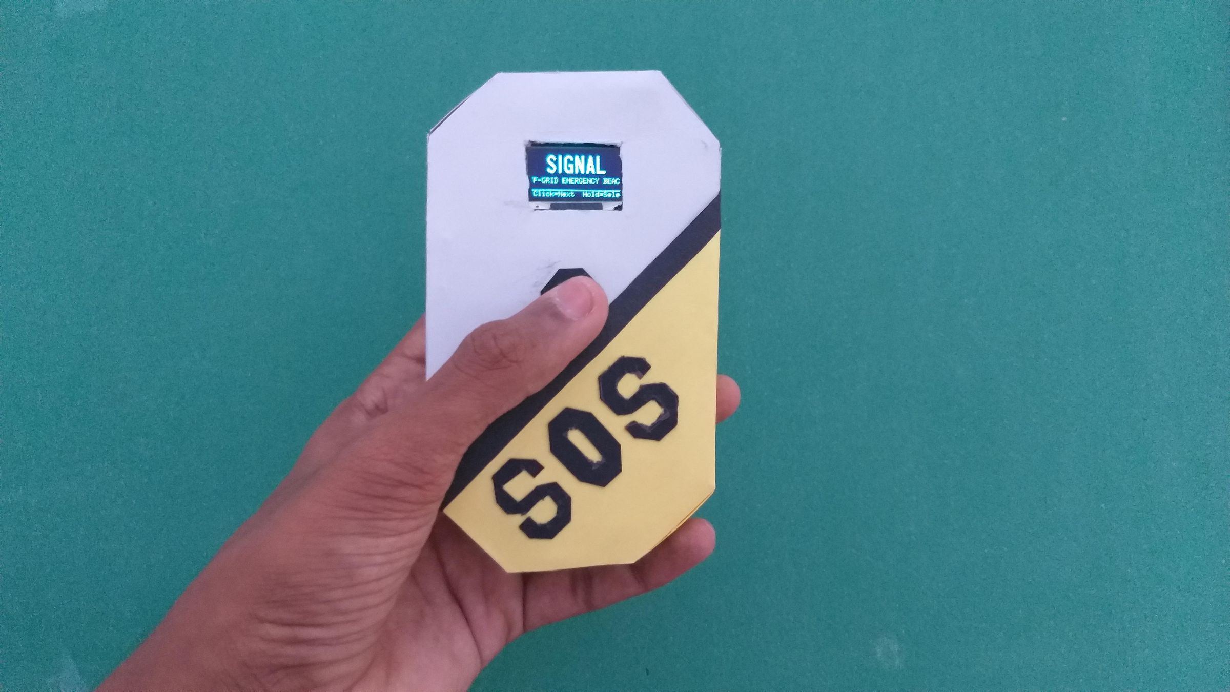
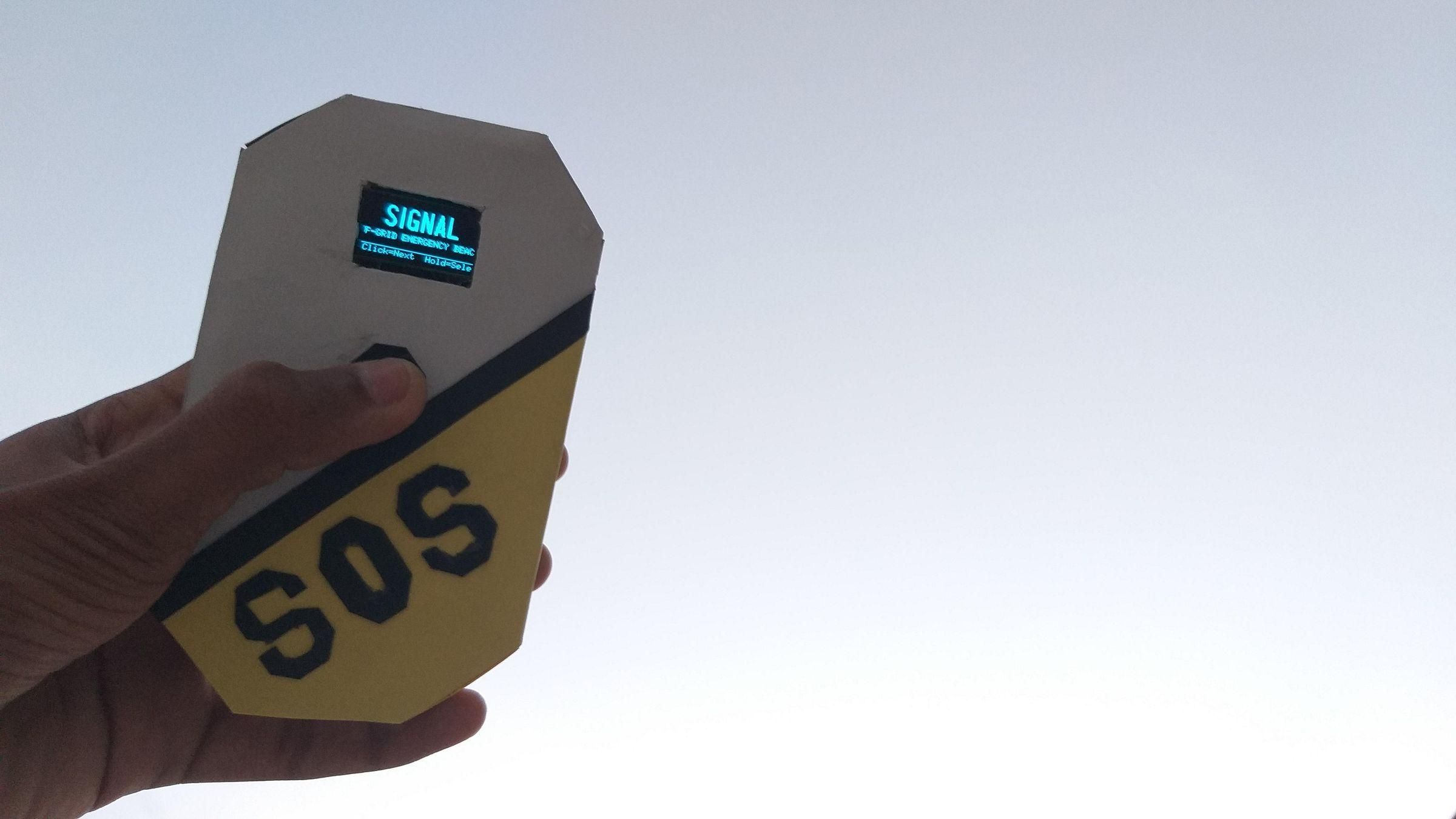

I read about a search and rescue case a while back — someone lost off-trail for the better part of a day, close enough to other people that a light or a signal fire would have been spotted almost instantly, but nobody nearby had any reason to look. No cell signal, no way to call for help, and just as importantly, no way to actively signal for it either. That gap stuck with me.
The uncomfortable truth is that almost all of our emergency communication assumes the grid is still up — cell towers, wifi, satellite services you pay a monthly fee for. But the moments people actually need to signal for help are disproportionately the moments that infrastructure fails: a wildfire that's taken out cell towers, a hurricane that's knocked out power and comms for days, a hiking trip somewhere with no signal to begin with, an earthquake that's left public utilities scrambling to even locate people, let alone reach them. In exactly the situations where public services can't get to you fast, most people are left with just their voice and whatever's in their pockets.
I had a drawer full of ESP32 boards from other projects and kept coming back to how much of what an emergency signaling device actually needs, those boards already do well: a way to blink or beep a message with precise, repeatable timing, and a radio that can talk to another nearby radio without any infrastructure in between. ESP-NOW specifically doesn't need a router, an access point, or even pairing — it just broadcasts, peer-to-peer, to anything listening nearby. That's the kind of "off-grid" behavior this contest is really about: something that works because the grid isn't there, not something that quietly depends on it anyway.
So I built SIGNAL — a single-button, pocket-sized device meant to do two things when public utilities can't:
- Pace out Morse code — SOS, MED, FIRE, LOST, HERE, OK — so anyone, with no prior knowledge of Morse, can flash a flashlight, bang on metal, or key a radio in perfectly timed code just by following what's on the screen. It turns a skill most people don't have into something anyone can execute correctly under stress.
- Broadcast a raw 2.4GHz distress beacon over ESP-NOW, so any other SIGNAL device nearby — no network, no cell tower, no internet — picks up the alert directly.
The prototype documented here is built from cardboard, hot glue, and parts pulled from a drawer, and that's deliberate. The entire premise falls apart if this only works as a polished, expensive build — it needs to be something anyone can make with basic tools and cheap parts, then upgrade later to PVC or a 3D-printed shell once the electronics are proven out. This isn't meant to replace real emergency services. It's meant to buy time and visibility in the exact window where those services can't reach someone yet — which, during a real disaster, is often the window that matters most.
Supplies
Electronics
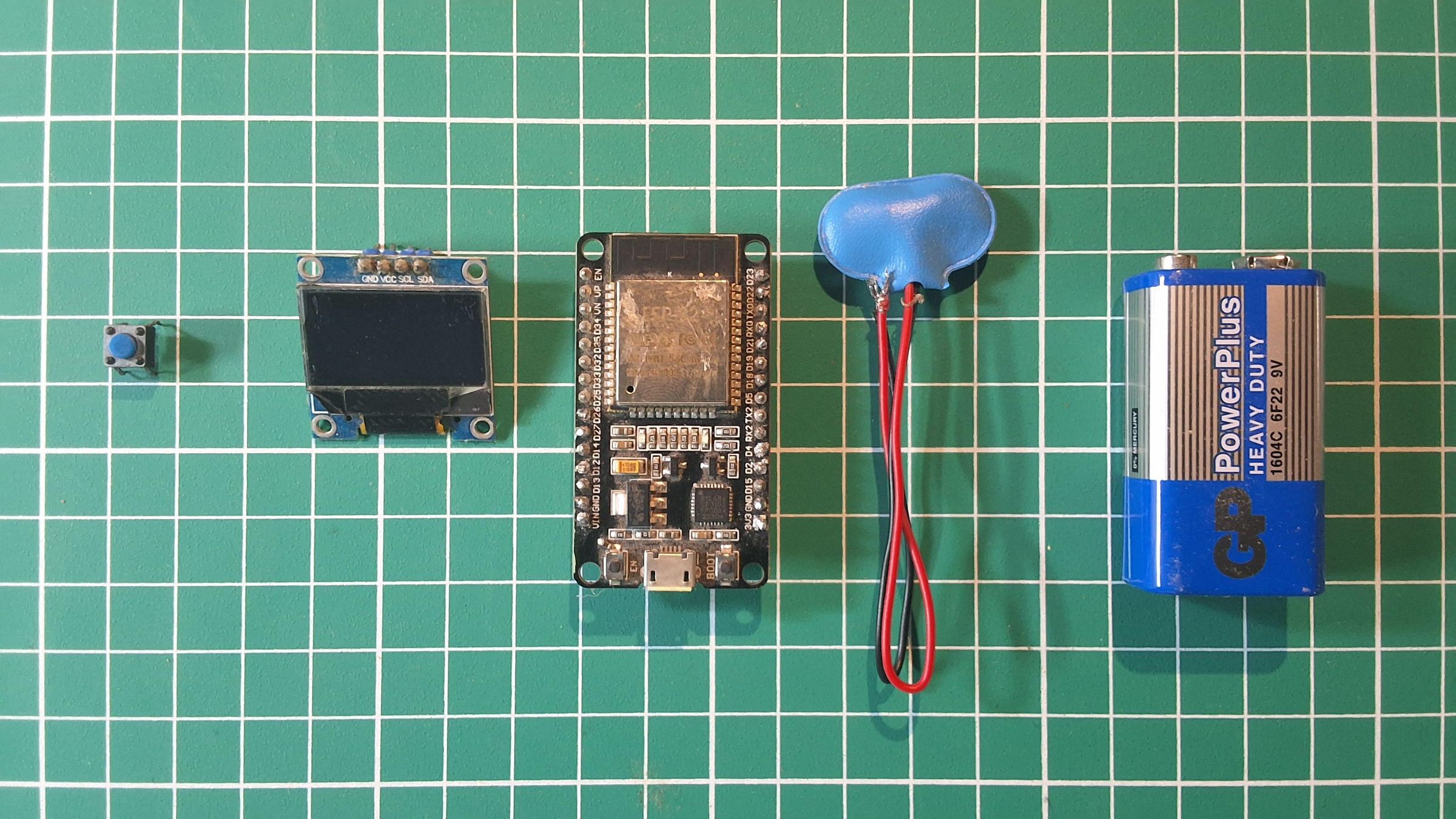
- ESP32 Dev Module (any standard 30/38-pin dev board works — this is what runs everything: the Morse engine, the display, and the ESP-NOW beacon)
- 0.96" SSD1306 OLED display, I2C, 128x64, blue or white (the default 4-pin I2C version — SDA/SCL, not SPI)
- 1x passive buzzer (or active buzzer — the code has a one-line toggle for either; I used passive so it can actually tone at a specific pitch instead of just clicking)
- 1x momentary tactile push button — this is the only input, so pick one that feels good to mash under stress
- Jumper wires (M-M and M-F depending on your button/buzzer leads)
- Breadboard (for prototyping the wiring before it goes in the enclosure)
- Micro-USB or USB-C cable (matching your board) for programming and power
Enclosure — cardboard version (what's pictured here)
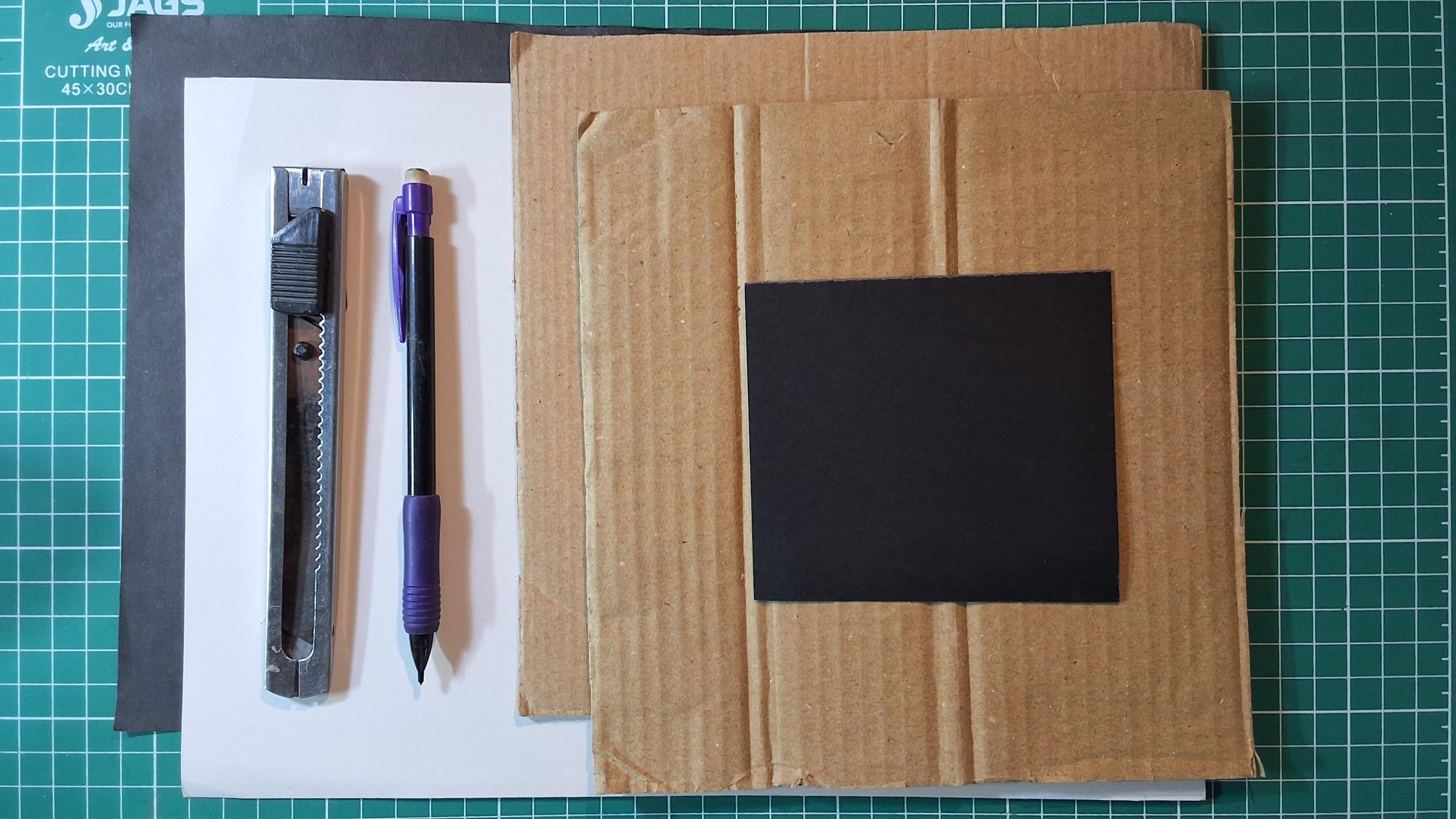
- Corrugated cardboard (an old shipping box is plenty).
- Hot glue gun + glue sticks
- Craft knife / box cutter + a metal ruler
- Pencil for marking cutouts
- Colored papers
Tools
- Soldering iron + solder.
- Computer with Arduino IDE installed
- USB drivers for your ESP32 board if this is your first time flashing one.
Wiring It Up
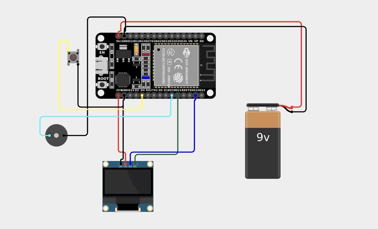
OLED display (I2C, 4 pins)
- VCC → ESP32 3V3
- GND → ESP32 GND
- SDA → ESP32 GPIO 21
- SCL → ESP32 GPIO 22
Push button
- One leg → ESP32 GPIO 4
- The other leg → GND
Buzzer(optional)
- Positive leg (usually the longer one, or marked +) → GPIO 19
- Negative leg → GND
Once it's all seated, plug the ESP32 into your computer over USB and move on to flashing the firmware — that's next.
Flashing the Firmware
With everything wired up, it's time to get the code onto the ESP32. (The code link is provided in 3rd step)
1. Install the Arduino IDE
If you don't already have it, download the latest version from arduino.cc. This project was built and tested using the standard Arduino IDE (2.x).
2. Add ESP32 board support
Then open Tools → Board → Boards Manager, search for "esp32," and install the package by Espressif Systems.
3. Install the U8g2 library
Open Sketch → Include Library → Manage Libraries, search for "U8g2," and install the library by oliver (olikraus). This handles all the OLED rendering — text, the inverted menu highlight, and the Morse light-guide box.
4. Select your board and port
Under Tools → Board, choose your specific ESP32 dev board (usually "ESP32 Dev Module" works fine for generic boards). Under Tools → Port, select the COM port / device your board shows up as once plugged in. If nothing shows up, you likely need the CP210x or CH340 USB driver, depending on which USB-to-serial chip your board uses.
5. Set the buzzer type
Near the top of the sketch, there's a single line:
Leave this as true for a passive buzzer, or set it to false if you're using an active one. This is the only line you need to touch before uploading, assuming your wiring matches Step 1.
6. Upload
Hit the upload arrow. The IDE will compile and flash the sketch — this takes a minute or so on a typical ESP32. Once it finishes, the board resets automatically.
Quick check
Within a second or two of reset, the OLED should show the "SIGNAL" splash screen. A single click should take you into the main menu, and clicking again should scroll through the preset list (SOS, MED, FIRE, LOST, HERE, OK, 2.4G BEACON) with the selected item highlighted in an inverted bar. If the screen stays blank, double-check the SDA/SCL wiring and that the I2C address in the code (0x3C) matches your specific OLED module — a small number of 0.96" boards ship on 0x3D instead.
How the Code Works
Code here
Before moving on to the enclosure, it's worth understanding what's actually happening inside the firmware — this isn't required to build SIGNAL, but it helps if you want to modify or extend it later.
Button handling
The entire device runs off one button, so the firmware polls it continuously without ever using delay() — a non-blocking debounce loop tracks press/release timing in milliseconds to distinguish a single click, a double click, and a long press (600ms+), so input never gets locked out while something else is happening on screen.
Morse engine
Each preset message (SOS, MED, FIRE, etc.) is converted into a sequence of dots, dashes, and gaps using a standard ITU Morse lookup table, expanded once into a timed symbol list when a preset is selected. A separate timing loop then steps through that list using millis(), turning the buzzer and the on-screen light guide on and off in sync — this is what drives the "LIGHT ON / LIGHT OFF" pacing you see during playback.
Display
All screens (splash, menu, Morse pacer, beacon status) are drawn using the U8g2 library over I2C. The menu highlight, the inverted Morse light block, and the live beacon counter are all just redrawn on a ~25 FPS refresh loop rather than being static images.
ESP-NOW beacon
Beacon mode initializes the ESP32's WiFi radio in station mode with no access point required, then sends a small packed struct — device name, status string, and an incrementing packet counter — to the broadcast address every 2.5 seconds. Because ESP-NOW is peerless and connectionless, any nearby ESP32 listening on the same channel can pick this up with zero pairing or network setup.
State machine
Everything ties together through one central state variable (splash → menu → Morse playback → beacon mode), with the button handler deciding transitions and each state having its own update and render function — keeping playback, beaconing, and menu logic cleanly separated.
Building the Cardboard Enclosure
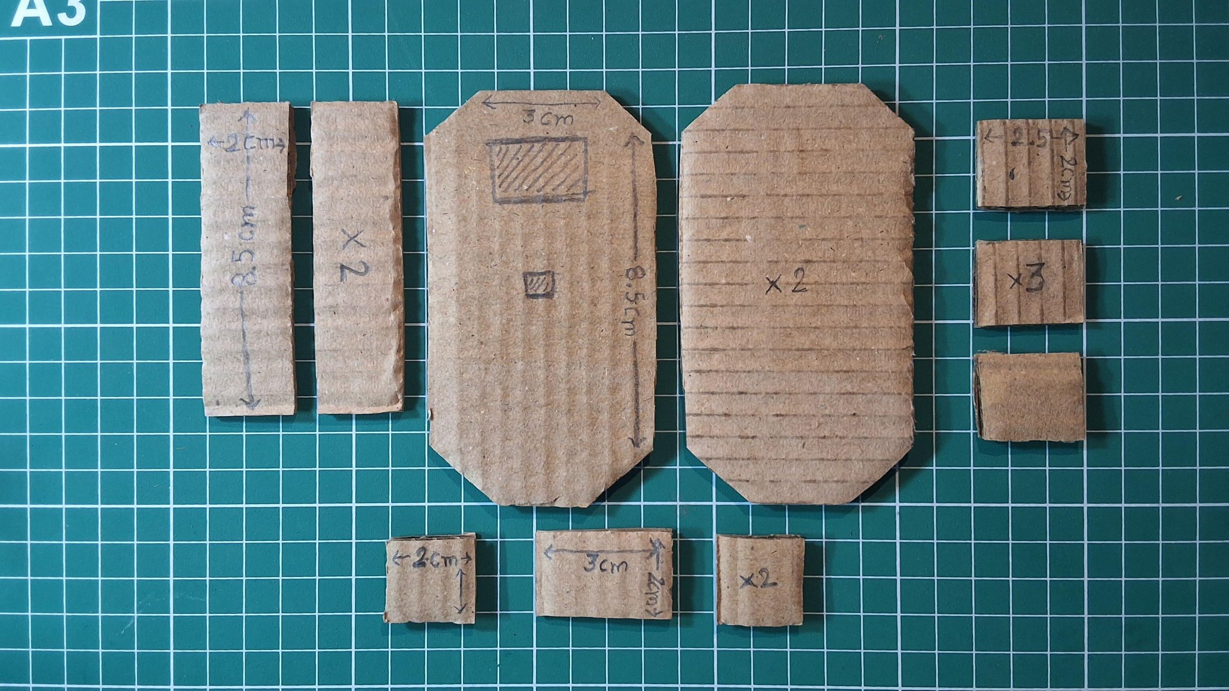
Here's the actual piece layout from the prototype, cut from a single sheet of corrugated cardboard with a craft knife against a cutting mat:
The pieces
- 2x side strips — 2cm x 8.5cm
- 2x plain panels — same 3cm x 8.5cm
- 3x small squares — 2.5cm x 2cm
- 2x small squares — 2cm x 2cm
- 1x small rectangle — 3cm x 2cm
Marking the front panel cutouts
Rather than working off fixed measurements, it's worth tracing your actual OLED module and button cap directly onto the cardboard before cutting — component sizes vary enough between suppliers that a "standard" dimension will fight you. The OLED window on mine sits centered near the top of the 3cm-wide panel; the button cutout sits below it, sized just under the button cap's diameter so the cap seats against the cardboard rather than falling through.
Assembly order
- Glue the two side strips to the base panel first, standing them upright along the base's long edges.
- Attach the front panel (the one with cutouts) and the plain back panel to close the box, lining up the clipped corners so the seams sit flush.
- Use the small squares as side panels, glued to the base at the corners, to close the enclosure.
- Glue the buzzer mounting tab behind the grille area on whichever panel you routed the buzzer holes into(Note : this buzzer is optional,you can skip this if you want),.
- Glue the oled in the window cutout made for it.
- Glue the other electronics on the back panel.
Dry-fit everything with the electronics inside before committing to glue on any seam — it's much easier to trim a wall down than to add cardboard back once it's stuck.
Final Assembly
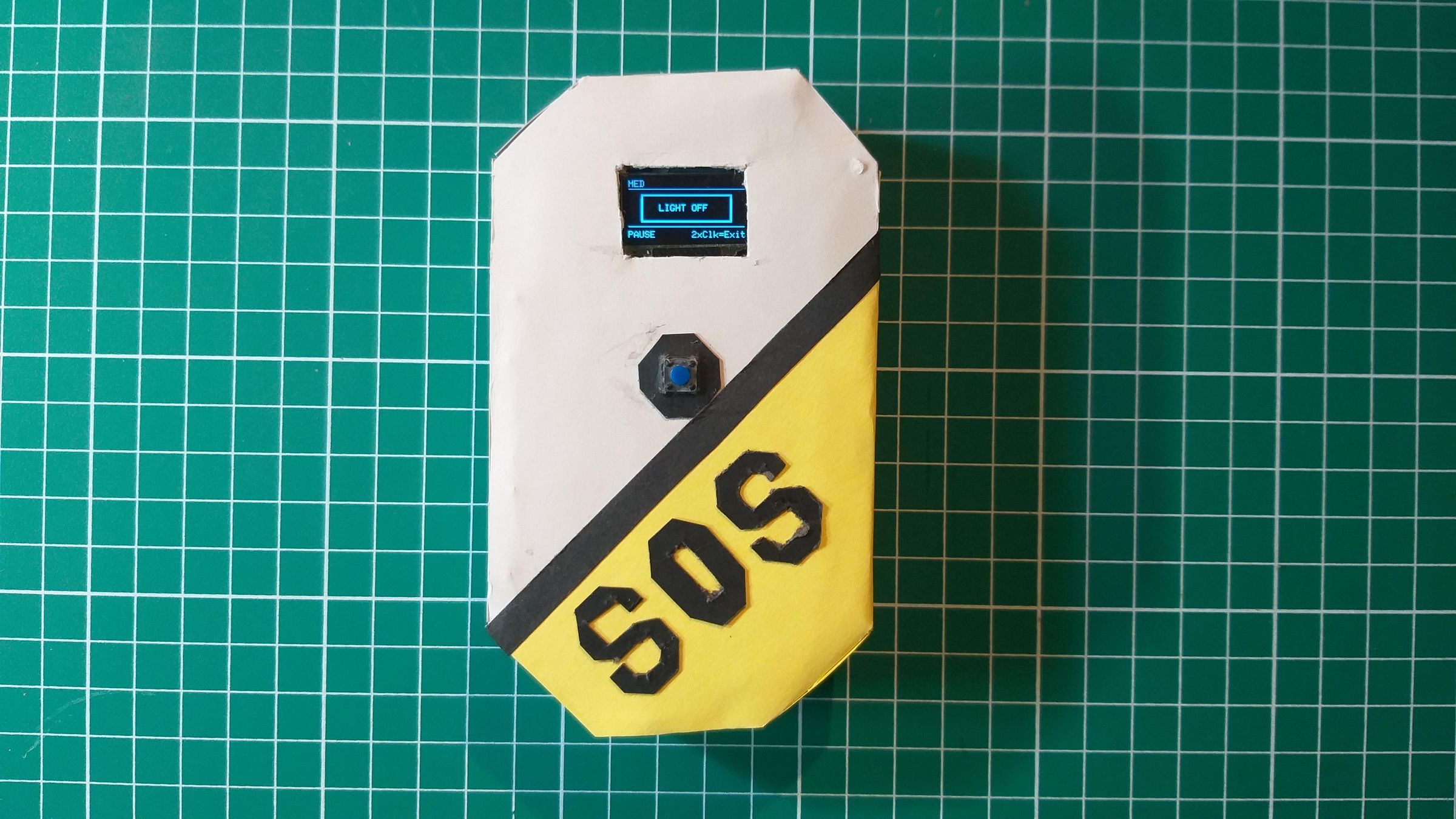
With the shell built and the electronics dry-fit checked, it's time to close everything up for good.
1. Reconfirm fit before any final gluing
Power the board on one more time with everything seated inside the enclosure — display against its window, button cap reaching through its hole, buzzer aligned with its grille. It's much easier to catch a misalignment now than after the last seam is sealed.
2. Route the USB or battery lead
If you're powering this over USB, decide now whether the cable will exit through a small notch in the back wall or the base — cut that notch before final gluing rather than after. If you're using a LiPo battery with a charging/boost module, this is the point to mount that module (hot glue works fine for holding it against an internal wall) and route its output leads to the ESP32's power pins.
3. Secure the electronics stack
Glue the standoff pieces down permanently, and add a small dab of hot glue or a cardboard tab across the top of the breadboard/perfboard to stop it shifting inside the case. The goal is that nothing inside moves when the case is tipped or dropped — that's the whole point of moving off a bare breadboard.
4. Close the final seam
Glue the last unglued wall or base panel shut. Run a bead of glue along the full seam rather than a few spot dabs — corrugated cardboard edges are the weakest point structurally, and a fully glued seam holds up considerably better under repeated handling.
Using SIGNAL in the Field
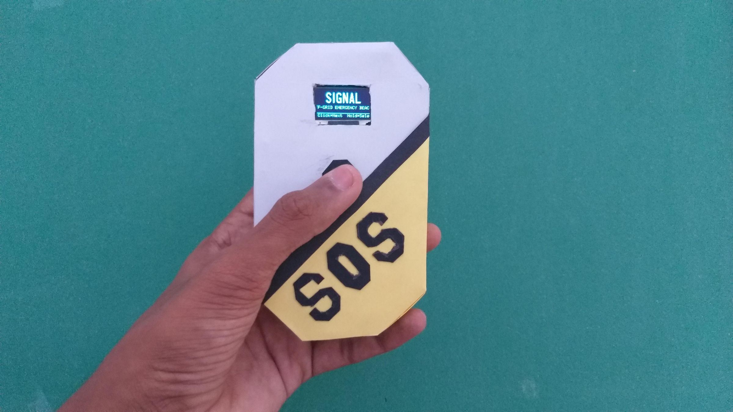
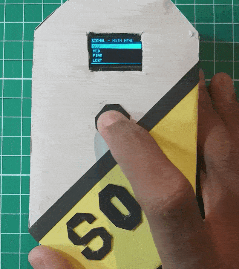
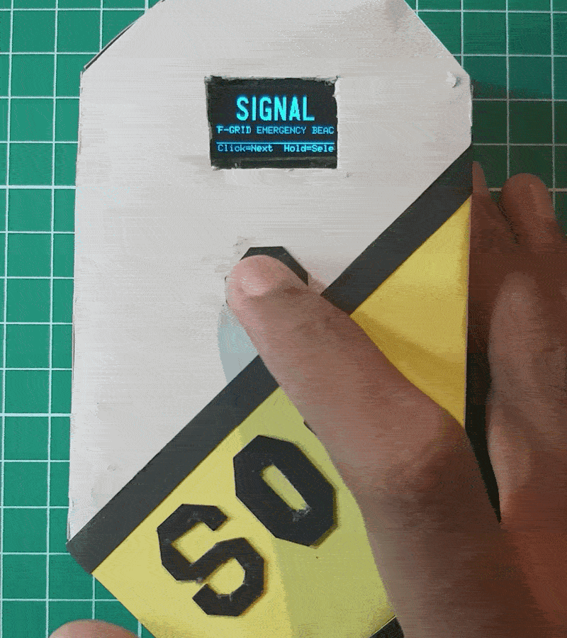
Everything is controlled through the single button, using three distinct actions:
- Single click — advance to the next item in the menu
- Long press (hold ~600ms) — select and activate the highlighted preset or mode
- Double click — instantly cancel whatever's playing and return to the main menu
Selecting a message
On power-up, SIGNAL boots to its splash screen and then drops into the main menu, showing the seven presets: SOS, MED, FIRE, LOST, HERE, OK, and 2.4G BEACON, with the currently selected item shown in an inverted highlight bar. Single-click cycles through them; a long press activates whichever one is highlighted.
Morse pacer mode (SOS, MED, FIRE, LOST, HERE, OK)
Once activated, the display switches into pacing mode. The top bar shows which message is active, and the center of the screen alternates between a filled block reading "LIGHT ON" and an outlined box reading "LIGHT OFF," synced exactly to the Morse timing for that message. Hold a flashlight in hand and simply toggle it on and off in time with the display — SIGNAL is doing the Morse translation and timing for you, so you don't need to know the code at all. The bottom of the screen also shows the current symbol (dot, dash, or pause) for reference. The message loops continuously until you double-click to stop it and return to the menu.
The onboard buzzer is optional here — it beeps in time with the same pattern if you have one wired in, but the visual light guide works fully on its own even without a buzzer connected, so it's not a required component if you'd rather build a stripped-down version.
2.4G Beacon mode
Selecting "2.4G BEACON" and long-pressing switches SIGNAL into a continuous ESP-NOW broadcast. Every 2.5 seconds, it sends out a distress packet — containing the device name, an emergency status string, and an incrementing packet counter — to any nearby device listening on the same channel, with no router, access point, or pairing required. The OLED shows a live transmission count and a "TX OK" indicator confirming each broadcast went out successfully, along with a short buzzer chirp per transmission if one is wired in. This mode is meant to run continuously in the background while the device sits with you or is left in a fixed, visible location; double-click at any point to stop broadcasting and return to the menu.
Going Further / Alternate Builds
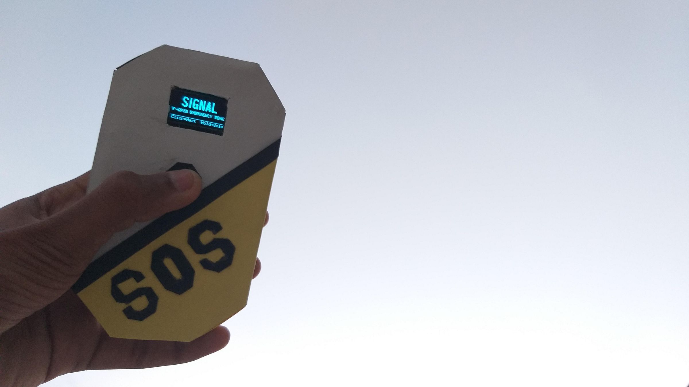
The version documented here is a working prototype — cardboard, hot glue, and whatever parts were on hand — but nothing about the design ties it to that specific enclosure. A few directions worth exploring:
Swapping enclosure materials
The wiring and firmware are entirely independent of what the shell is made from. A 3mm PVC sheet, cut with the same craft knife or on a laser cutter, would give a more rigid and weatherproof housing while keeping the exact same cutout layout used here — same OLED window, same button hole, same buzzer grille. A 3D-printed enclosure is another natural step up: model a case around the same footprint (roughly matching the panel dimensions from Step 4), and it becomes something durable enough to actually carry on a hike or keep in a go-bag long term, rather than a bench prototype.
Dedicated receiver unit
Right now, a SIGNAL beacon broadcasts its distress packet over ESP-NOW, but nothing is set up specifically to listen for it. A second, stripped-down ESP32 build — no button menu needed, just power and a display — could sit as a fixed base station, printing out any received packets with a timestamp and signal source. That turns this from a "signal into the void and hope someone's listening" tool into an actual two-node distress system.
Solar or better power
The prototype runs on USB or a basic LiPo setup. For genuinely off-grid, multi-day use, adding a small solar panel and charge controller ahead of the existing LiPo boost module would let SIGNAL trickle-charge during the day and be ready to broadcast at night, without ever touching a wall outlet.
Weatherproofing
Cardboard obviously isn't weather-resistant. Between a PVC shell, a silicone seam seal, or simply a resealable waterproof bag as an outer layer, this is an easy problem to solve once the internals are finalized — worth doing before relying on this in any real outdoor scenario.
Extending the preset list
The Morse presets and beacon status string are both defined as simple lookup tables in the firmware, so adding new messages (a custom call sign, a different emergency type) is a matter of editing a couple of lines, not restructuring the code.
Conclusion
SIGNAL didn't start as an attempt to build something impressive — it started as a reaction to how easily a person can be reachable by almost everyone except the one thing that could actually help them in an emergency. Cell networks, wifi, cloud services: all of it depends on infrastructure that disasters are specifically good at destroying. What doesn't depend on any of that is a battery, a radio chip, and someone willing to signal for help in a way that doesn't need permission from a grid.
This build is intentionally simple: one button, one display, one buzzer, and code that turns a fairly obscure skill (Morse code) into something anyone can execute correctly on the first try, under pressure, without training. It's a cardboard prototype, not a finished product — and that's the point. The barrier to building this yourself is a handful of common parts and a free afternoon, not a fabrication lab or a specialized skill set.
Off-grid resilience doesn't have to mean expensive, over-engineered gear. Sometimes it's a $10 microcontroller, a lookup table of dots and dashes, and a decision to make sure that when the towers go down, there's still a way to say I'm here and be understood.