DIY CHEAP SIM Racing Wheel (XBOX Compatible)
by aadhav in Circuits > Microcontrollers
519 Views, 2 Favorites, 0 Comments
DIY CHEAP SIM Racing Wheel (XBOX Compatible)
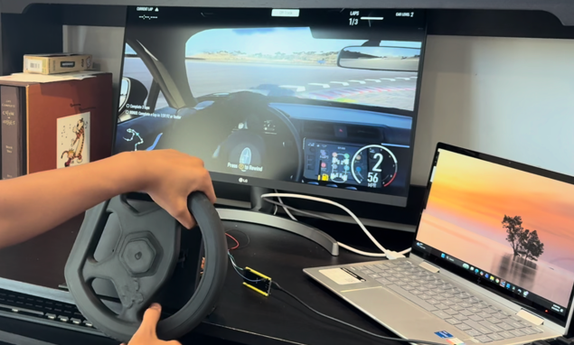

I am 14 years old and I wanted to build a SIM-racing wheel from scratch, a real functional steering wheel that can behave like a professional one without the $400 price tag. I realized that I couldn't get any better at racing with just a regular Xbox controller so I decided to get a SIM racing wheel. But after scouring through Amazon, I realized why would I want to spend $400 on a game. So, I decided to build my own and expand my knowledge of CADing, coding, and wiring. After tens of hours of making, I built my own SIM racing wheel which I can finally play Forza with. Let's get into it. You can play this on the XBOX app which is what I'll be doing. Also, if you want to watch how I made it from beginning to end you can check out my YouTube channel where I posted a video about it. https://youtu.be/TRNeyp2r6ho Check out my YouTube Channel here: https://www.youtube.com/@MakeLabs-i4p?sub_confirmation=1
Supplies

Electronics
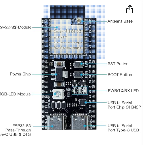
- ESP32‑S3 Dev Board (with USB‑OTG)
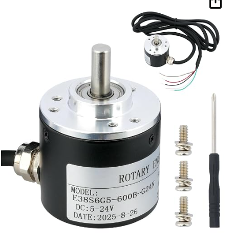
- Taiss E38S6‑600‑24G industrial rotary encoder (600 PPR)
- Jumper wires (male–female)
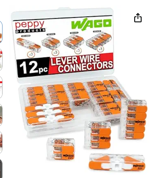
- Wago 221 connectors
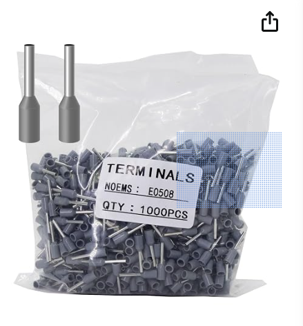
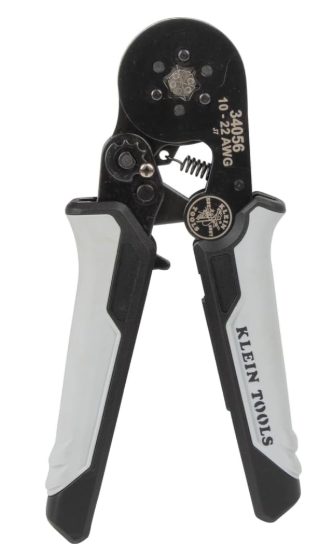
- Ferrules
- External 7.2V battery
- USB‑C cable (for programming)
- USB‑C cable (for OTG)
Hardware
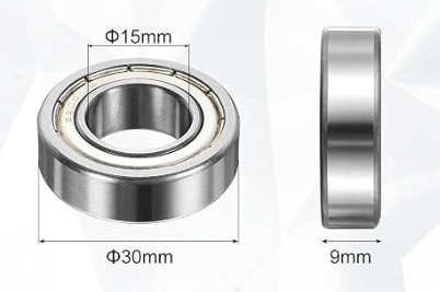
- 15mm X 30mm X 9mm bearings
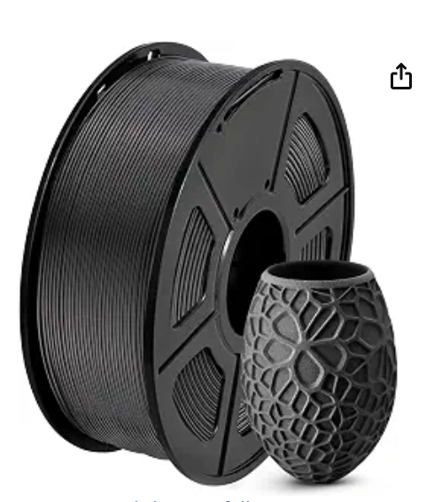
- PLA filament
- Rubber Bands
Tools
- Multimeter(optional)
- Pliers/Crimpers
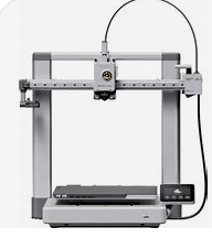
- 3-D printer
Watch my Youtube video about the materials
3D Print the Parts
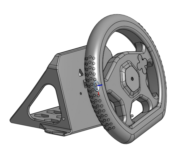
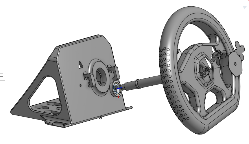
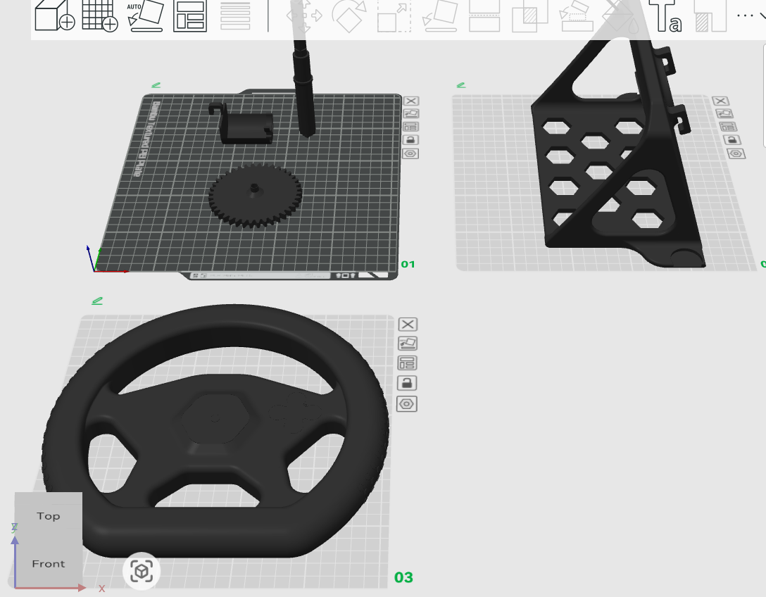
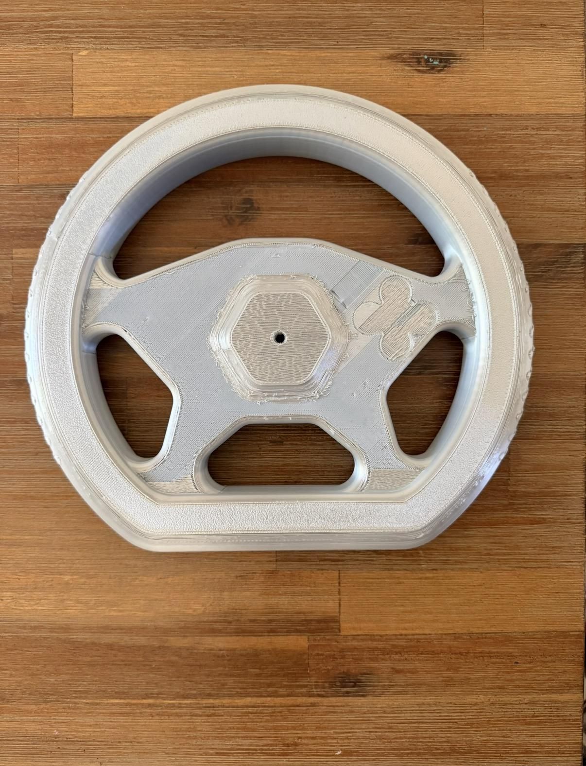
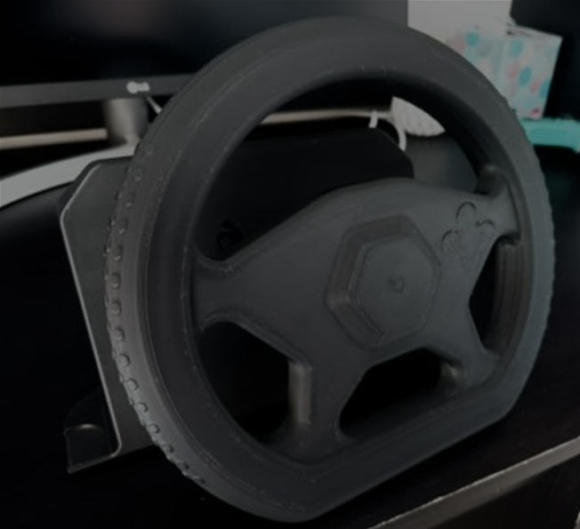
Use my files from Makerworld to print all of the parts:
Suggested Print Settings:
Material: PLA recommended for all parts
Infill: 20% for wheel. 15% for everything else.
Supports: Enabled for all parts.
Top Z Distance: .275mm for easy support removal
After printing take off all supports
Optional: Use a deburring tool to clean the part
Electronics and Wiring
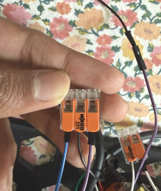
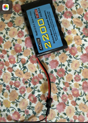
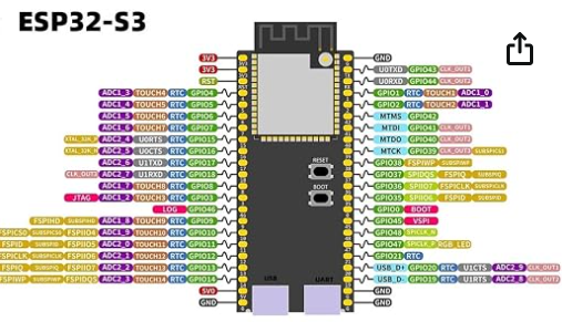
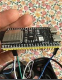

This project uses an ESP32‑S3 and a Taiss E38S6‑600‑24G industrial rotary encoder. The encoder outputs quadrature signals (A/B) using open‑collector outputs, which means the ESP32‑S3 must provide internal pull‑ups on the signal pins.
Below is the exact wiring setup I used to get clean, stable readings.
Parts Used:
ESP32‑S3 Dev Board (USB‑OTG capable)
Taiss E38S6‑600‑24G Encoder (600 PPR)
Male-Female Jumper Wires
Male-Male Jumper Wires
Ferrules + crimp tool/pliers
Wago 221 connectors
USB‑C cable
The encoder has four active wires:
- Red – VCC (5 V)
- Black – GND
- White – Channel A
- Green – Channel B
The metal shield wire is not used. To make sure it doesn't disturb and signals, cut it down to 5-6mm then wrap around it with electrical tape.
What To Do with the Encoder Wires:
Take a ferrule and put it over the exposed part of each of the Encoder wires, then either take your ferrule crimping tool and crimp the ferrule (which is connected to the exposed wire) so that when you give it a tug, it does not come off. This is called a tug test. If you don't have a crimper then just use pliers. You'll want to repeat this step for each of the exposed wires (red, white, green, and black).
Connecting the Wires:
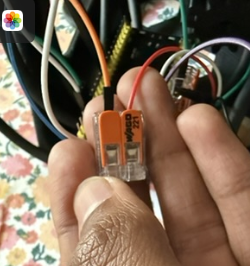
For the Red Encoder Wire: Remember the red wire we just put a ferrule over? Good. Now take that wire and put it into a two port Wago. This will look like the one in the picture area. Once you have put the red encoder wire in one of the ports. Take one orange (for color-coding sake) male-male jumper wire. Put one of the ends into the only port of the Wago which is left. Then, take the other end of the male-male jumper wire, which is loose, and insert it into the red slot of the 7.2V battery pack. Do not put it into the black slot. Only put this wire in at the end for now keep it loose or else a flame will appear. That's one wire done and out of the way! To make sure you did it right be sure to check in the pictures above.
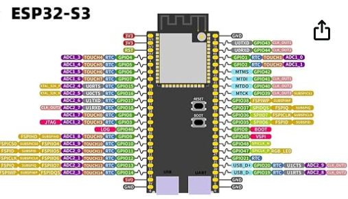
For the Black Encoder Wire: Take the black wire we just put a ferrule over and insert it into a three port Wago. It should look exactly like the one in the pictures above. It should go into the middle port. Take one purple (for color-coding sake) male-male jumper wire and insert it into one of the two Wago ports left in the 3-port Wago. Then, take the other loose end of the wire and insert it into the black slot of the 7.2V battery pack. Only put this wire in at the end for now keep it loose or else a flame will appear. We still have one more port to do. For this take a male-female jumper wire (I did purple for this wire). Insert the male end into the port. Take the female end and insert it into ground on the ESP32-S3. Above I have a picture with where all the pins are on the board. To make sure you did it right be sure to check in the pictures above.
For the Green Encoder Wire: Take the green wire we just put a ferrule over and insert it into a two port Wago. This will look like the one in the picture area except it will only have two ports instead of three. Once you have taken that green wire which was connected to the encoder and put it into one of the ports. Take one green (for color-coding sake) male-female jumper wire. Put the male end other port of the Wago and put the female end in the GPIO 5 pin. This is for reading signals sent from the encoder. Above I have a picture with where all the pins are on the board.
For the White Encoder Wire: Take the white wire we just put a ferrule over and insert it into a two port Wago. This will look like the one in the picture area except it will only have two ports instead of three. Once you have taken that white wire which was connected to the encoder and put it into one of the ports. Take one white (for color-coding sake) male-female jumper wire. Put the male end other port of the Wago and put the female end in the GPIO 4 pin. This is also for reading signals sent from the encoder. Above I have a picture with where all the pins are on the board.
Assembling 3-d Printed Parts
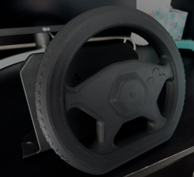
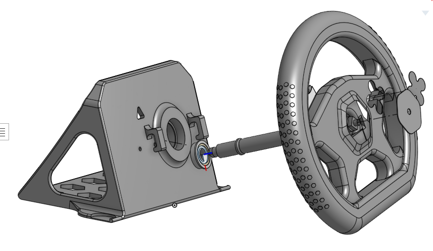
Now that you have printed out:
- Wheelbase
- Wheel
- Axle
- Encoder Holder
- Gears
It's time to start putting everything together:
To start take the axle. Also take the bearing you bought. Make sure you bought the exact one mentioned or it won't fit in the axle. Now inserting the axle into the bearing. It should only be able to fit in one of the ends (the smaller one). Once you've found that end put it in and if it isn't going in like at all get some sanding paper and sand it down a bit (this shouldn't be the case). If you have gotten it on, put it in halfway through.
Now take the wheelbase. Then, take the axle with the bearing on it, and put it in the hole which should be big enough to hold the bearing in. This may take some trial and error.
Take the wheel, and when you turn it to the back you should see a hole with a square inside of it. Insert the axle into the hole, so that it matches up with the axle. You should insert the axle the opposite side of where the bearing is.
Now, take the 12-tooth gear. on the inside you should see a square. With the wheel, axle, and bearing all attached to the wheelbase, turn the wheelbase so that the back of it is facing you. Then, insert the gear in the axle with the long rectangular prism.
Take the wheelbase. Take the encoder holder. Put the hook of the encoder holder and put it on the inside of the wheelbase, so that it hooks onto the triangle hole.
After all of this you should still have one 40 tooth gear left. We will use this in the next step.
IF you didn't understand something explained here, feel free to go to my YouTube video where I show how to make this.
Setting Up Gears and Encoder in Build
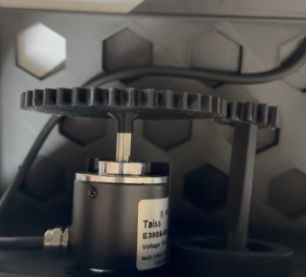
As you can see in the picture above. You should attach the 40-tooth gear onto the encoder. Then, place the encoder on the encoder holder. Adjust the position so that it meshes with the 12-tooth gear. To make sure it works, try to spin the wheel itself to see if all the gears move. If it does. Congrats! You are one step closer to finishing the build
Adding Rubber Bands
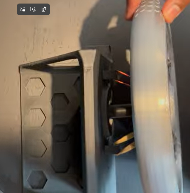
On the wheelbase there should be two hooks. And on the back of the wheel there should also be two hooks. Attach rubber bands like in my YouTube video at 10:00. Basically, what I do here is twist the rubber band then fold it to make it smaller. Then, put one side of the rubber band on the wheelbase and one side on the wheel.
How the Code Works
The encoder sends two signals to the ESP32-S3. The ESP32 uses these signals to detect how far and in which direction the steering wheel turns.
When I enter the center command, the current position is saved as the middle of the wheel. The code then converts the wheel position into a value between fully left and fully right. A small deadzone prevents unwanted movement near the center.
The steering value is sent to the computer through USB. The ESP32 appears as a normal game controller, so no special driver is needed.
The program repeats this process every millisecond:
- Read the encoder.
- Calculate the steering position.
- Send the position through USB.
- Check for calibration commands.
The wheel angle can be calculated from the encoder count:
angle= (centered count×360)/counts per revolution angle
My encoder produces 600 pulses per revolution. Quadrature decoding counts four edges for every pulse, giving:
600×4=2400 counts per revolution600×4=2400 counts per revolution
The configured steering limits can be changed to match the wheel’s mechanical travel and gearing.
Software Setup
Before using the code, download:
- ESP-IDF 6.0.2 using the ESP-IDF Tools Installer.
- Visual Studio Code and its Espressif IDF extension (optional, but easier).
ESP-IDF installs Python, CMake, Ninja, and the ESP32 compiler automatically.
Connect ESP32-s3 to Computer
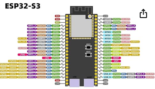
Take a USB-USB C cable. Connect the USB side to one of your COM ports. Connect the USB-C to the UART port. This is the port you should use when downloading the code.
Download the Code
Download the code here
You can use this code in VS Code (which is what I used).
Test the Wheel
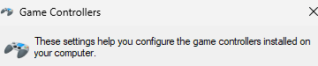
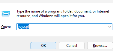
The next step is to test if the code actually works! First connect the USB-C to the USB port on the ESP32. Then, press Windows button + R. There you'll see a text box. Type joy.cpl, press open. then click the only controller there. It should be labeled SIM Racing wheel or controller. Click on it. then click "Properties". Then turn the wheel. You should also see the crosshair move on the screen!
Get It Setup to XBOX
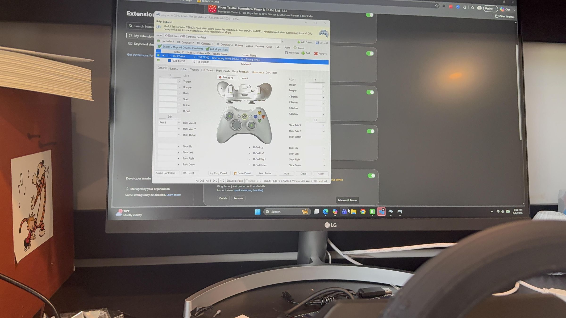
Some games only support Xbox controllers. For these games:
- Download x360ce 4.x from x360ce.com.
- Extract it and open x360ce.exe.
- Open Issues and install ViGEmBus if requested.
- Select Controller 1, then Add.
- Choose Sim Racing Wheel.
- Enable Mapped Device.
- Map the steering axis to Left Thumb X.
- Select Save All.
- Minimize x360ce and leave it running while playing.
Now your wheel can be recognized as an Xbox Controller.
YOU DID IT!
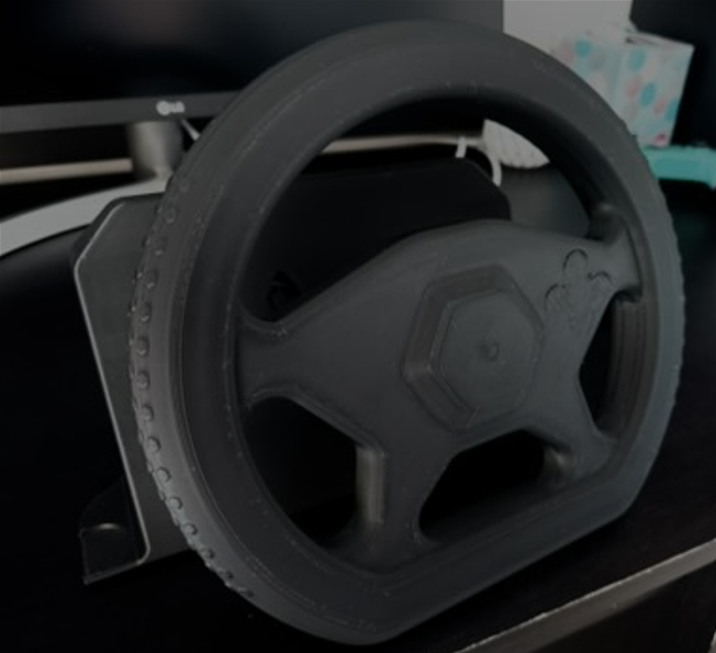
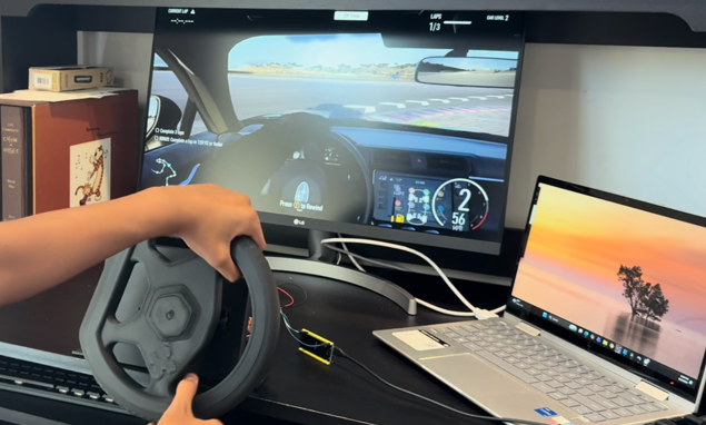
Building this DIY sim‑racing wheel from scratch was more than just a weekend project — it was a full engineering journey. I went from wiring an industrial encoder, to decoding quadrature signals, to designing custom CAD parts, to writing firmware for the ESP32‑S3, and finally turning everything into a fully functional XInput steering wheel that works with PC games and Xbox Cloud Gaming.
Along the way, I learned how to:
- read and stabilize encoder signals
- use ferrules, Wagos, and proper wiring techniques
- design and print mechanical parts that fit real hardware
- map raw sensor data into smooth steering input
- build a custom USB/XInput device from the ground up
- troubleshoot power, grounding, and signal noise
- integrate electronics, firmware, and CAD into one complete system
The final result is a fully working sim‑racing wheel that feels great to use and proves what’s possible with accessible tools, creativity, and persistence. This project blends electronics, microcontrollers, mechanical design, and problem‑solving — exactly the kind of engineering challenge I love.
If you decide to build your own version, feel free to remix the CAD files, improve the firmware, or even expand the project with pedals, a display, or force feedback. I hope this inspires you to try something ambitious, learn something new, and build something you’re proud of.
Thanks for reading — and happy racing!