SMPS Based Power Supply 90v-220v AC to 30V 10A Output With IC TL494.
by rupjit81 in Circuits > Electronics
106 Views, 0 Favorites, 0 Comments
SMPS Based Power Supply 90v-220v AC to 30V 10A Output With IC TL494.
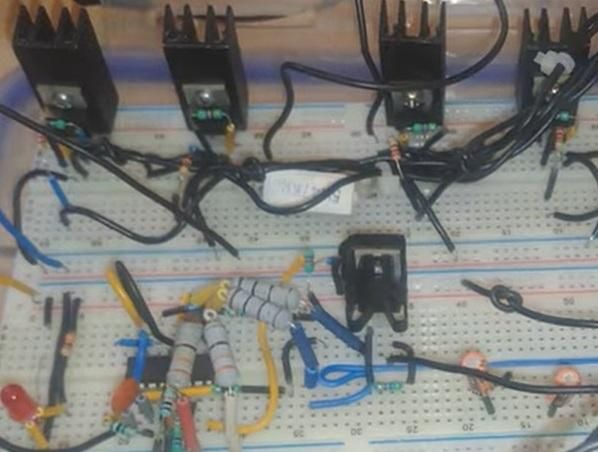
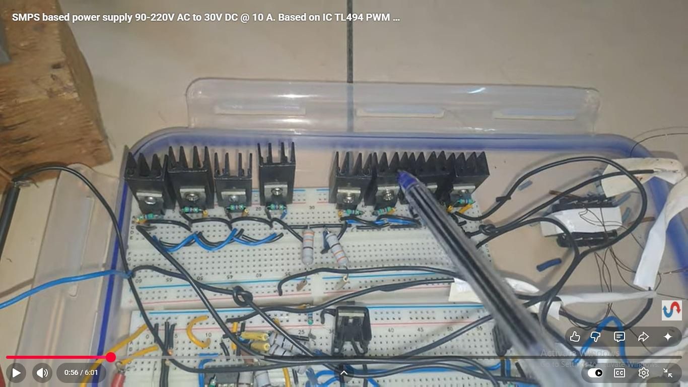

In this Instructable Im going to demonstrate the design of a high frequency switching power supply. Im going to discuss this design in steps. The circuit runs on input voltage of 90V - 220V AC and gives output of 30V DC @ 10 A.
Supplies
C1 22PF
C2 2200UF/50V
C4 1000UF/25V
C4 820UF/250V
C5 820UF/250V
C6 0.1 uF
D1 MUR3060PT
D2 30A Bridge
D2 1N4007 BRIGBE
J1
J2
J3
L
L1 CHOKE
Q1 IRF840
Q2 IRF840
Q3 IRF840
Q4 IRF840
Q5 IRF840
Q6 IRF840
Q7 IRF840
Q8 IRF840
Q9 IRF840
Q10 IRF840
R1 100K
R2 100K
R3 4.7K
R4 4.7K
R5 10K
R6 10K
R7 330E 1W
R8 4.7K
R9 100E 1W
R10 1 OHM 10W
R10 100E 1W
R11 4.7K
R12 10K
R13 47K 5W
R14 4.7K
R15 4.7K
R16 1 MEG
R17 4.7K
R18 330 E 1 W
R19 4.7K 1/4W
R20 330E 1 W
R21 1K
R22 10K
R23 1 K
R24 4.7K
R25 4.7K
R26 4.7K
R27 4.7K
R28 4.7K
T1 PULSE TRANSFORMER
T2 MAIN TRANSFORMER
T3 220 TO 12 V TRANSFORMER
U1 TL494
Downloads
Oscillator & PWM Control With IC TL 494
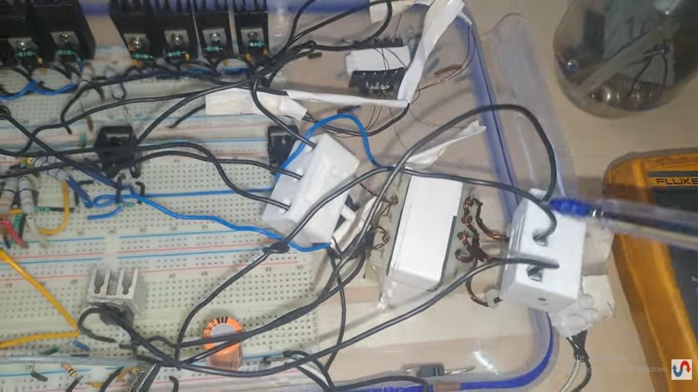
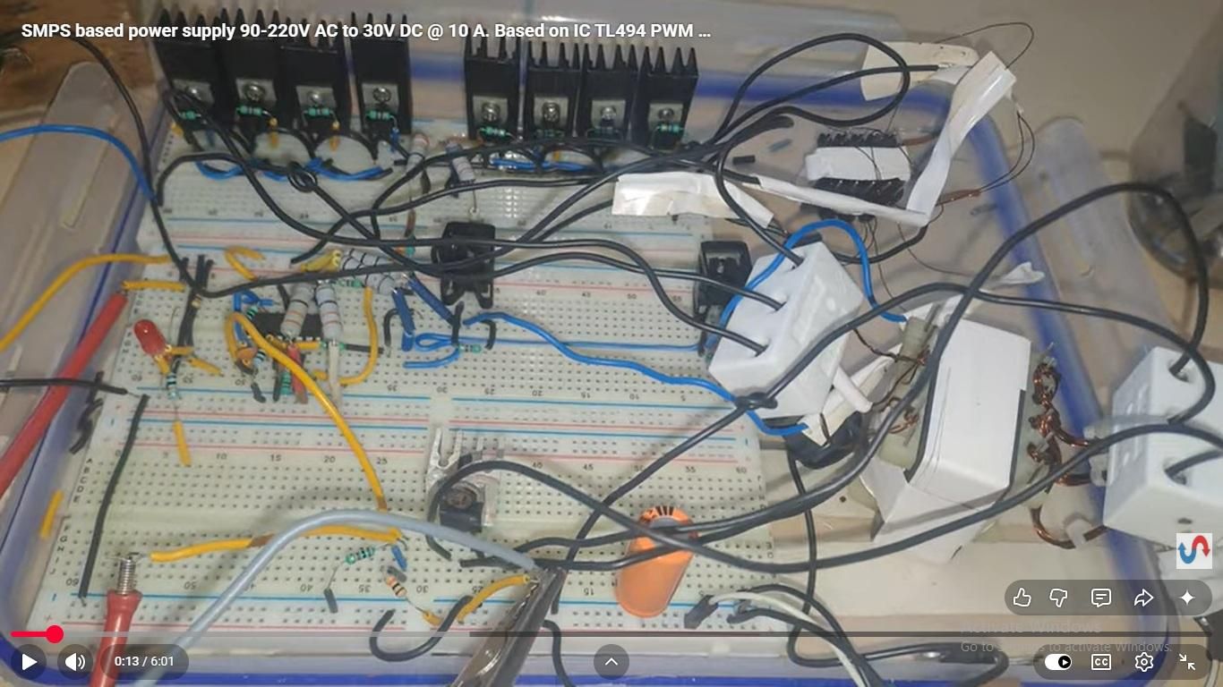
The circuit uses IC TL494 as an oscillator and PWM controller. The circuit is designed at 53KHZ operating frequency. It currently uses the voltage feedback loop. The current feedback loop is not used. It will be used in upgrade version of this circuit. Output of IC TL494 is fed to two driver mosfets used to drive driver transformer T1. This transformer uses a bifilar winding. Each coil is 10 turns.
This circuit is the control circuit and it is fed with a seperate 12V power supply based on transformer T3.
Downloads
Power Stage With Mosfet IRF840
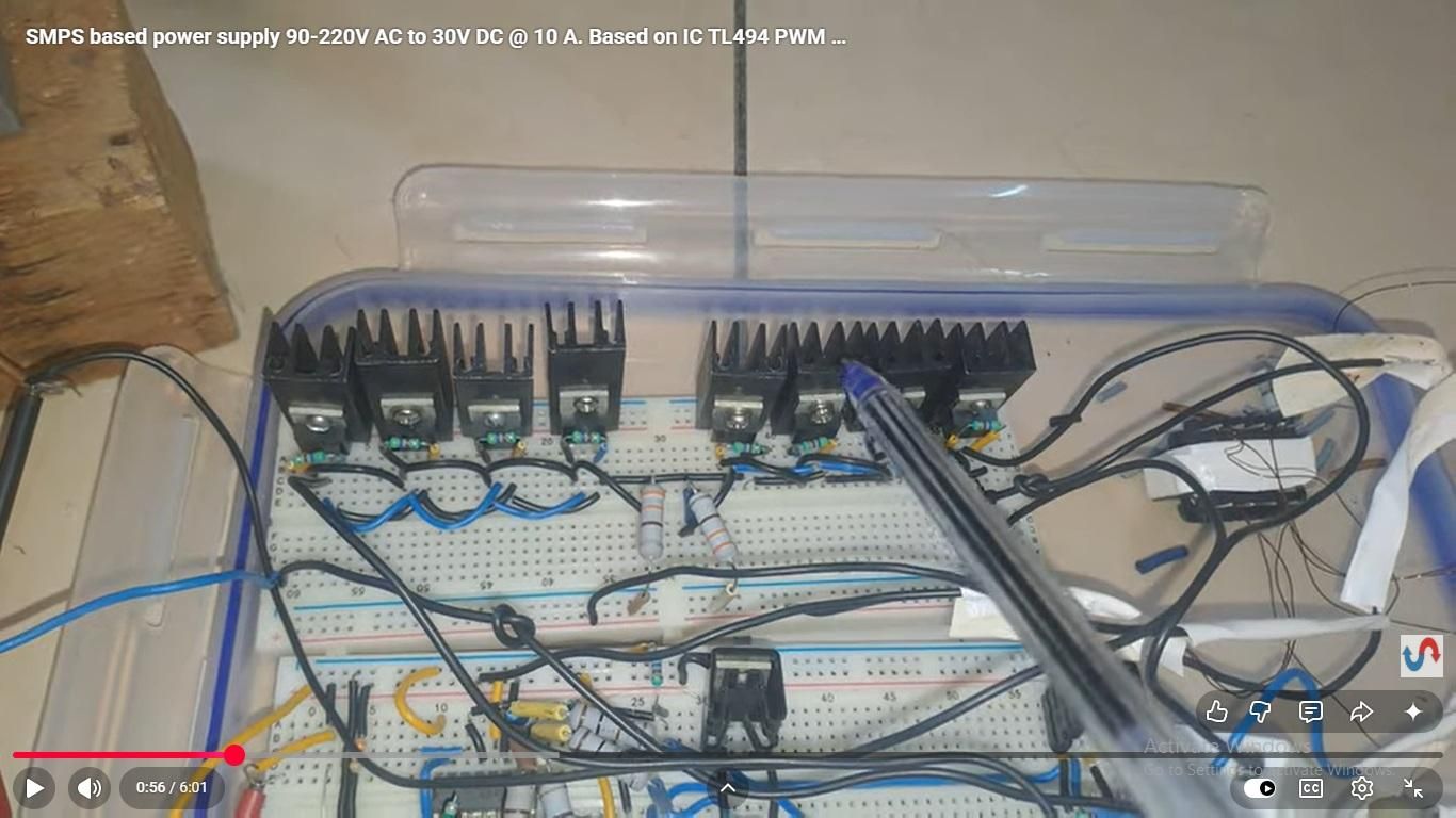
The power stage is mentioned in sheet 3. We are using 4 mosfets in parallel on each drive groups.
We have two drive groups A and B. Both use IRF840 mosfets. 4 no. in each group. so the power stage is having total 8 mosfets.
There are 4.7k 1/4w resistances on each mosfet gate. These are connected between gate and source of each mosfet.
The main power transformer is T2. Primary winding is 19 turns bifilar winding and secondary is 6 turns bifilar winding. 26 SWG wire is used in primary and secondary. 2 stands in primary and 6 strands in secondary.
The gate drive signal of mosfets are connected to transformer T3. Refer to complete circuit diagram.
Downloads
Transformer Design
Please see the transformer design attachment file.
Conclusion
The circuit uses high voltage mains line. Also it deals with heavy power. Skilled professionals only should try to make it. Safety to be considered at all times.
The circuit is tested and therefore can be made.