Scrolling Text Display (A to Z Guide)
by diyperspective in Circuits > Arduino
36455 Views, 238 Favorites, 0 Comments
Scrolling Text Display (A to Z Guide)

In this instructable / video I will guide you with step by step instructions how to make scrolling text display with Arduino.
I won't be explaining how to make code for Arduino, I will show you how to use existing code. What and where you need to connect and install that you could make scrolling text display like this without any previous knowledge of Arduino.
Arduino software - https://www.arduino.cc/en/Main/Software
Code and library - http://bit.ly/arduinocodelibrary
Original link - https://github.com/riyas-org/max7219
Provided Amazon links are affiliates
Tools You'll Need:
- Router https://amzn.to/2DVXXZC
- Drill: https://amzn.to/2U5QQmL
- Jigsaw https://amzn.to/2rg4uXx
- Fretsaw https://amzn.to/2Ece851
- Clamps https://amzn.to/2E8EBkQ
- Small clamp https://amzn.to/2Pto6AQ
- Tape measure https://amzn.to/2rfS4Ph
- Combination square https://amzn.to/2PtmtmN
- Small utility knife https://amzn.to/2L6Gi2J
- Hot glue gun https://amzn.to/2PdCgpI
- Digital Multimeter https://amzn.to/2rf0EO3
- Soldering kit: https://amzn.to/2Q613Bf
- Wire cutting pliers https://amzn.to/2rvrL80
- Wire Stripper https://amzn.to/2PvTK0z
- Soldering helping hand https://amzn.to/2EedeoI
Materials You'll Need:
- 6mm thickness plywood (local hardware store)
- Small wood screw (local hardware store)
- Wood glue: https://amzn.to/2E8Baus
- Wood oil https://amzn.to/2UrHKB0
- Epoxy https://amzn.to/2Q8N3GU
- Electrical tape: https://amzn.to/2QsKK0P
- Sandpaper https://amzn.to/2M1mUE7
- Silicone feet https://amzn.to/2PbfWgs
- Arduino Nano https://amzn.to/2PuatkY
- 8x8 LED Display 2x https://amzn.to/2L8Gmz0
- Protected 18650 Li-Ion battery https://amzn.to/2PrZ7y0
- 18650 battery holder https://amzn.to/2SyZMzw
- Booster module https://amzn.to/2rwVIEl
- On/Off switch https://amzn.to/2PwVruS
- Breadboard https://amzn.to/2PxftVY
- Wires (local hardware store)
You can follow me:
- YouTube: https://www.youtube.com/channel/UCaaSGD6wIhpYZhav...
- Instagram: https://www.instagram.com/diyperspective
- Twitter: https://twitter.com/diyperspective
- Facebook: https://www.facebook.com/diyperspective
Preview
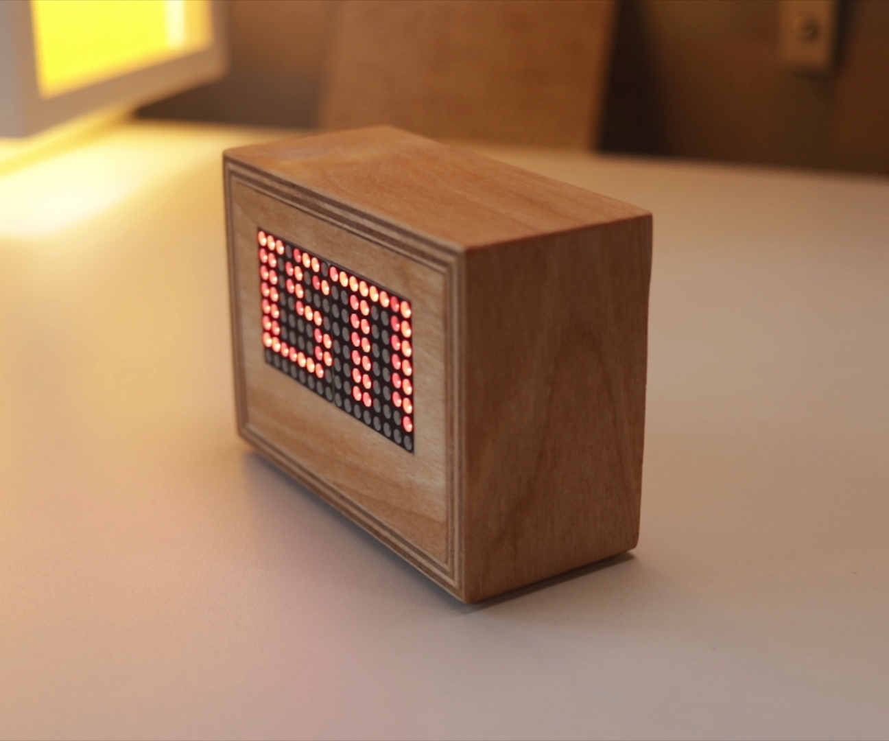


Preview of the mini scrolling text display.
Like what I do? Consider becoming a PATRON! This is a great way to support my work and get extra benefits! https://www.patreon.com/DIYPerspective
Cutting Plywood


To make a simple box first I cut sides, top and bottom from 6mm plywood. Add painters or electrical tape to prevent any chipping.
New Jig


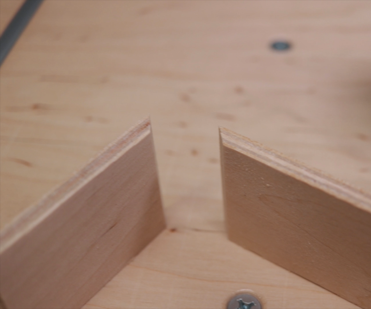
If you wondering, this is my new jig for bevel cuts for my jigsaw table. It's very simple jig, but very useful.
Clamped stop block helps to cut pieces at the same size.
Gluing


Connect all sides with painters tape and glue them.
Cutting Front and Back


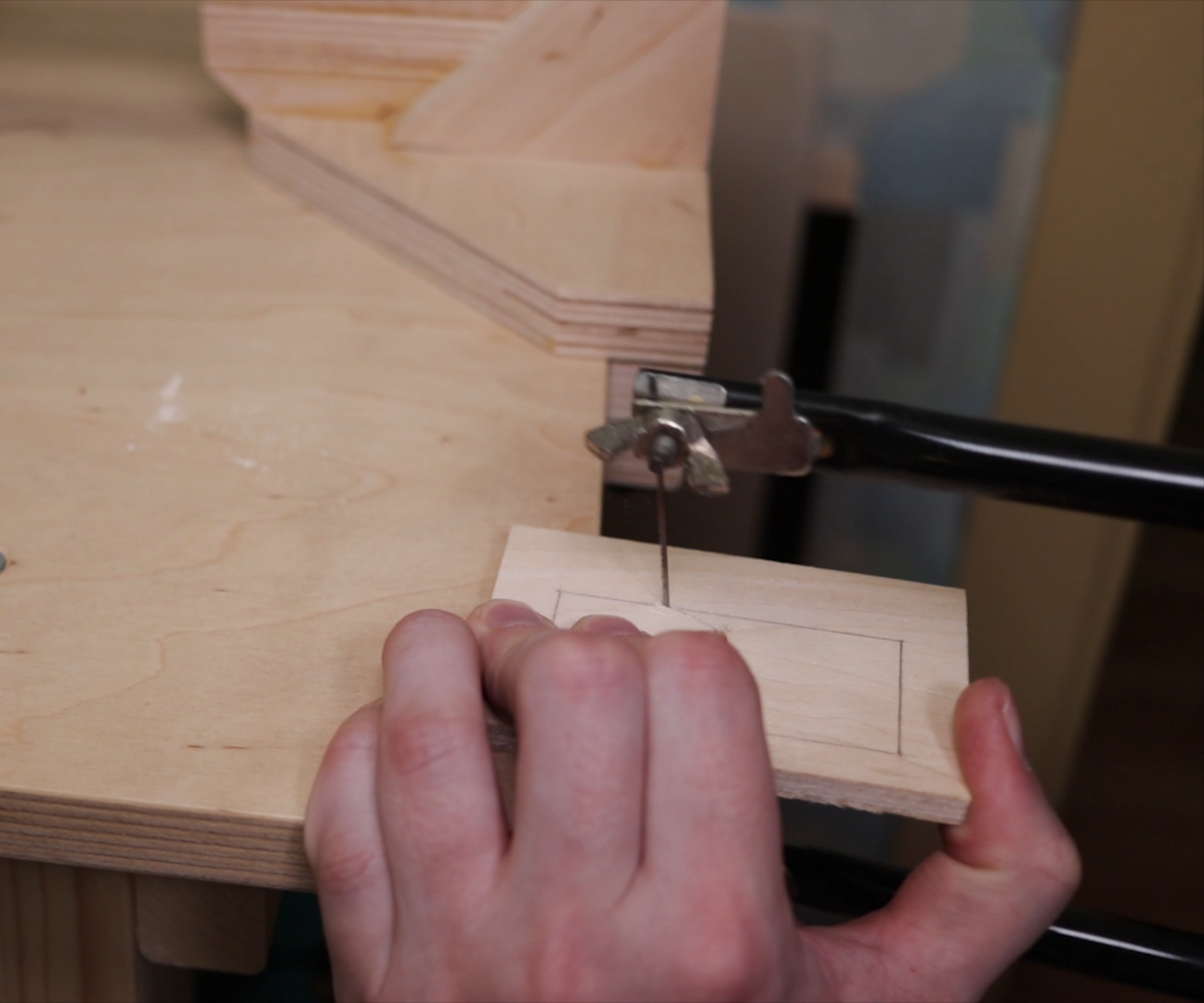

Then I cut front and back pieces. In front piece I drilled hole and made hole for LED displays with a fretsaw.
To get straight looking cuts I trimmed inside with a jigsaw.
Making Slot for the Chips


I routed slots for chips of the LED display, as I wanted that display would be flush with outside of the front piece.
Components That You Need

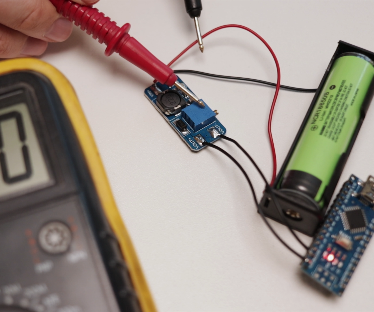

For this build you need (links in first page):
- Arduino Nano
- 2x 8x8 LED displays
- Voltage booster
- Protected 18650 battery
- Battery holder
- On/Off switch
Before soldering Voltage booster to the circuit make sure to adjust it's output voltage to 5V with potentiometer on the chip.
Before Soldering


Download and install Arduino software - https://www.arduino.cc/en/Main/Software
If you get prompt messages like in a picture just agree and install.
Download Additional Files


That code would work you need extra libraries for the Arduino. Download here https://github.com/riyas-org/max7219
Unzip it and copy "MaxMatrix" folder to Arduino's "libraries" folder and you are good to go.
Arduino Software Set Up


When you start Arduino software first you need to choose Arduino type. In our case it's Arduino Nano (1st picture).
Then you need to open Serial Monitor window (2nd picture).
If you get red error like this, you need to choose right USB port in which your Arduino is connected (3-4th picture).
Just try choosing different ports until you can open Serial Monitor window without error (4-5th picture).
Uploading the Code
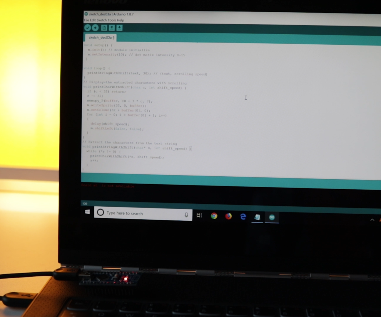


Now you need to copy ant paste entire code to the new empty sketch file.
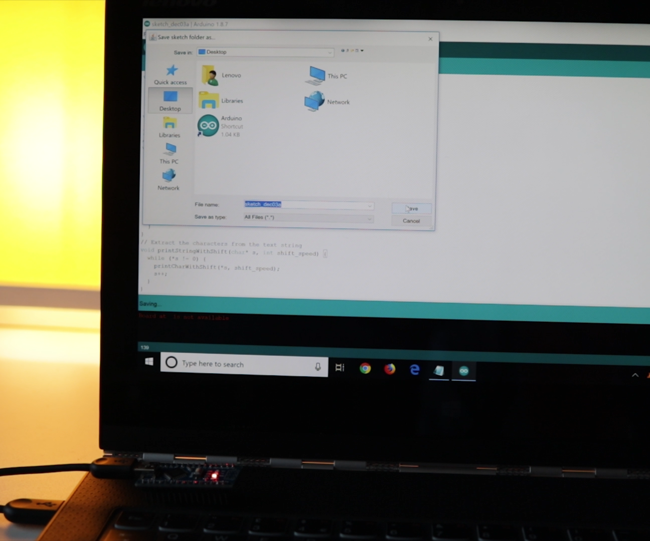
Press upload button, it will ask that you save project file.
Program starts compiling/generating code and starts uploading.
Error While Uploading


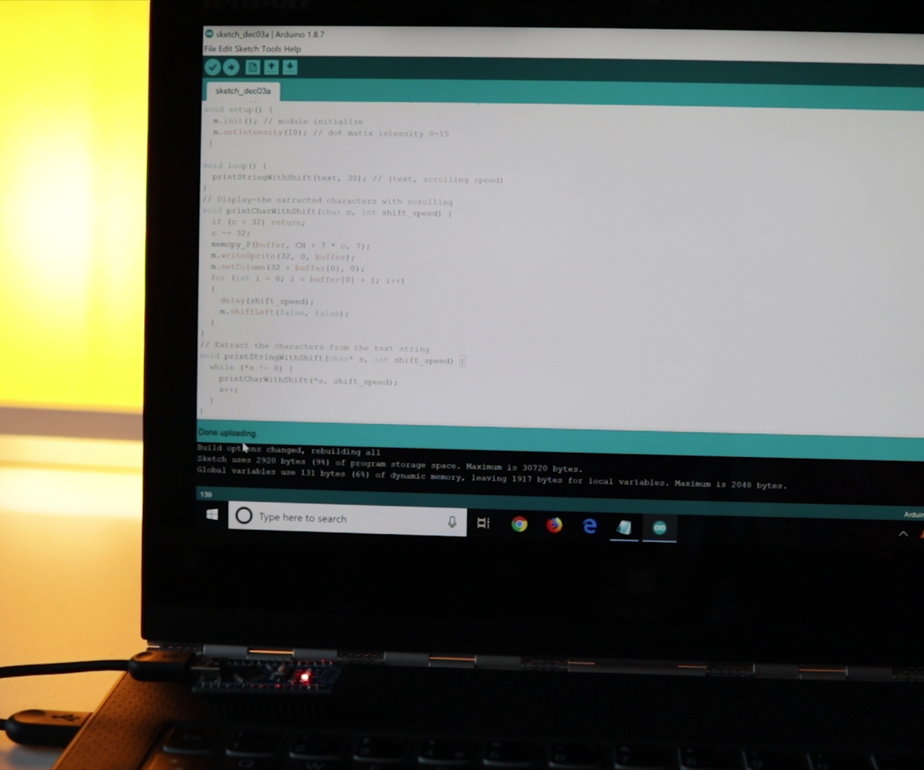
If your upload take a while (15s+) and you get red error message like this you need to change Processor "ATmega328P" to Processor "ATmega328P (Old bootloader)".
Now upload should be successful.
Configuring Display


You can customize showing text, scrolling speed and display brightness at these locations (see pictures).
Battery Life
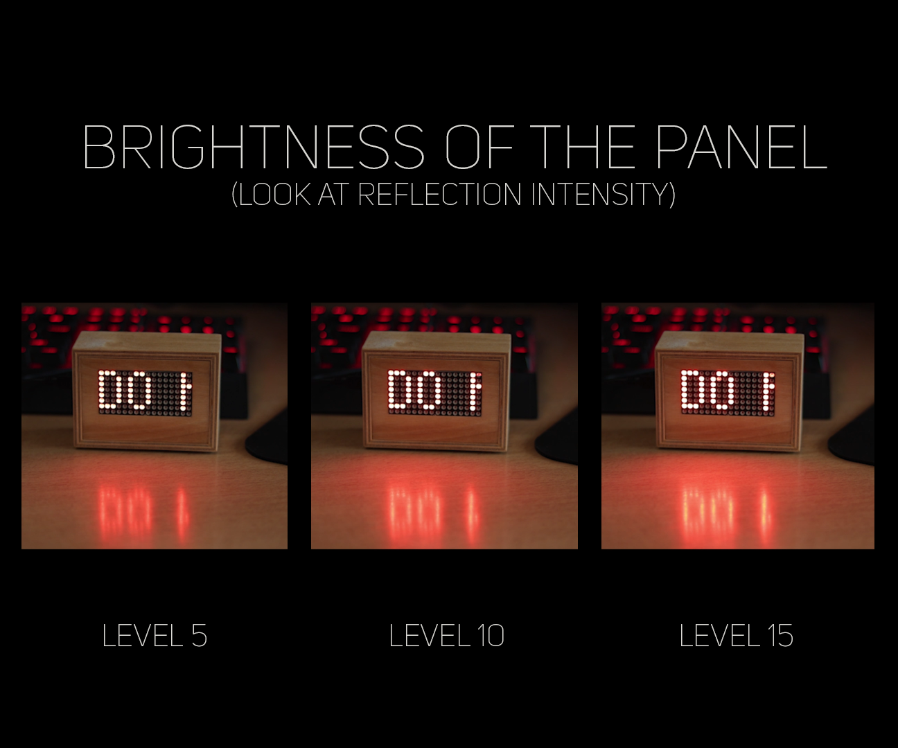
With 3000 mAh battery at Level 5 brightness display should run more than 20 hours, at 10 – more than 14 hours and at 15 – more than 12 hours. Also you can power it from a wall charger.
Making Display


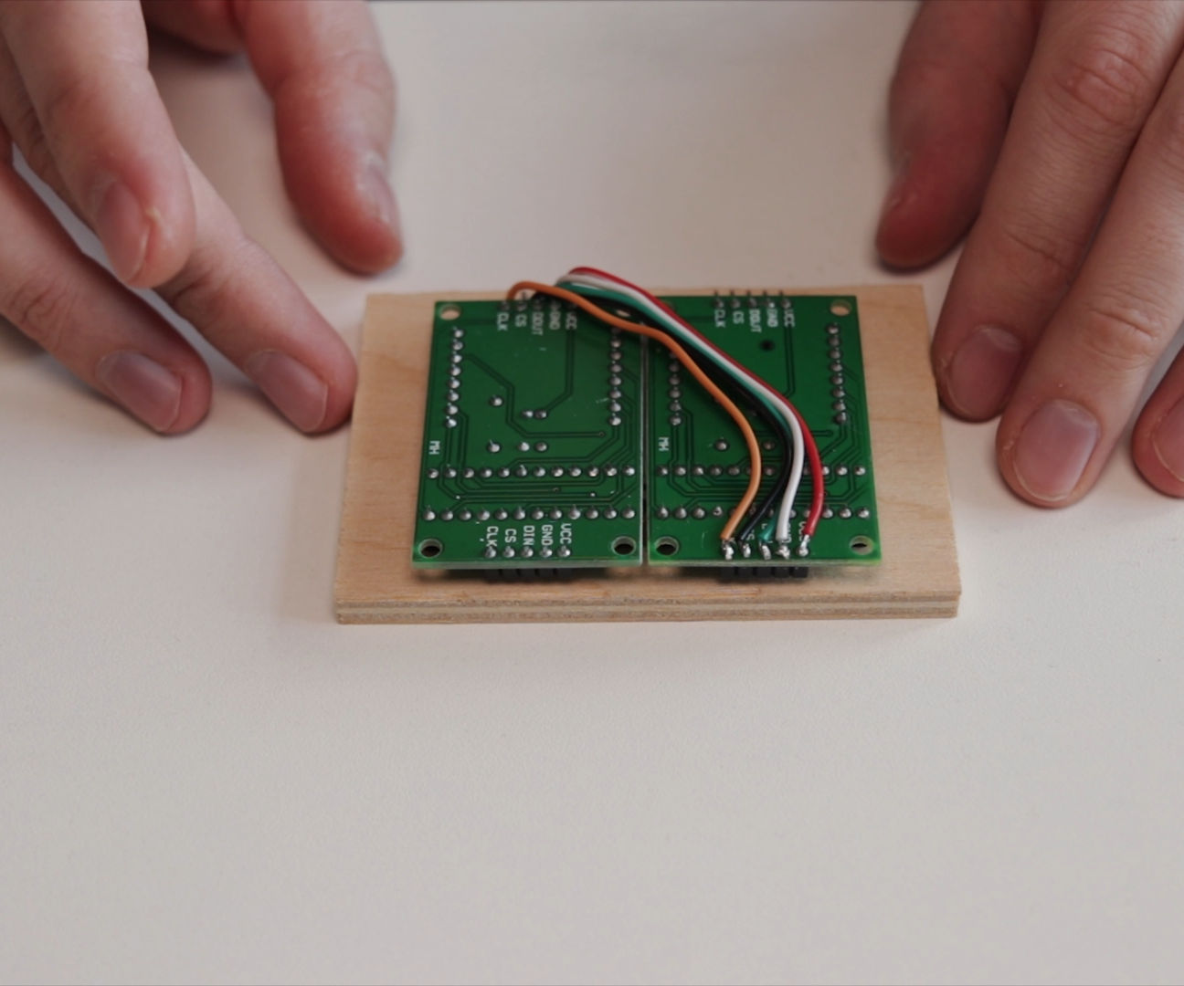

Back to the build, I cut pins, and soldered wires:
- From first display top - VCC to VCC - on second display bottom.
- From first display top - GNDto GND - on second display bottom.
- From first display top - DOUT to DIN - on second display bottom.
- From first display top - CS to CS - on second display bottom.
- From first display top - CLK to CLK - on second display bottom.
And then I hot glued display to the plywood.
Making Holes
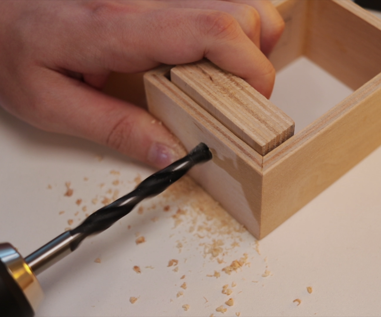


One hole must be made for USB mini cable and other for the power button.
Small Blocks and Battery Holder


I glued two squares that back piece won’t go further inside from the top. And to prevent going inside from the bottom will help this battery holder with battery inside. To glue it use something like 30 minute epoxy.
Soldering Wires


I soldered 5 wires to the first display's bottom.
Connecting Display to Arduino


Wires from LED display goes to Arduino:
- VCC to 5V
- GND to GND
- DIN to D12
- CLK to D11
- CS to D10
Wires from voltage booster (VOUT+ and VOUT-) will go to VIN (+) and GND (-).
Small Blocks in the Front


Also I glued small blocks on which later I will glue front piece with LED displays.
Final Soldering


Wires that I previously soldered to Arduino's VIN and GND goes to voltage booster's VOUT+ AND VOUT-.
Two extra wires must be soldered to power switch.
One wire from power switch goes to batteries Positive contact and other to booster's VIN+ contract.
And the Negative wire from the battery goes to booster's VIN- contact.
Testing

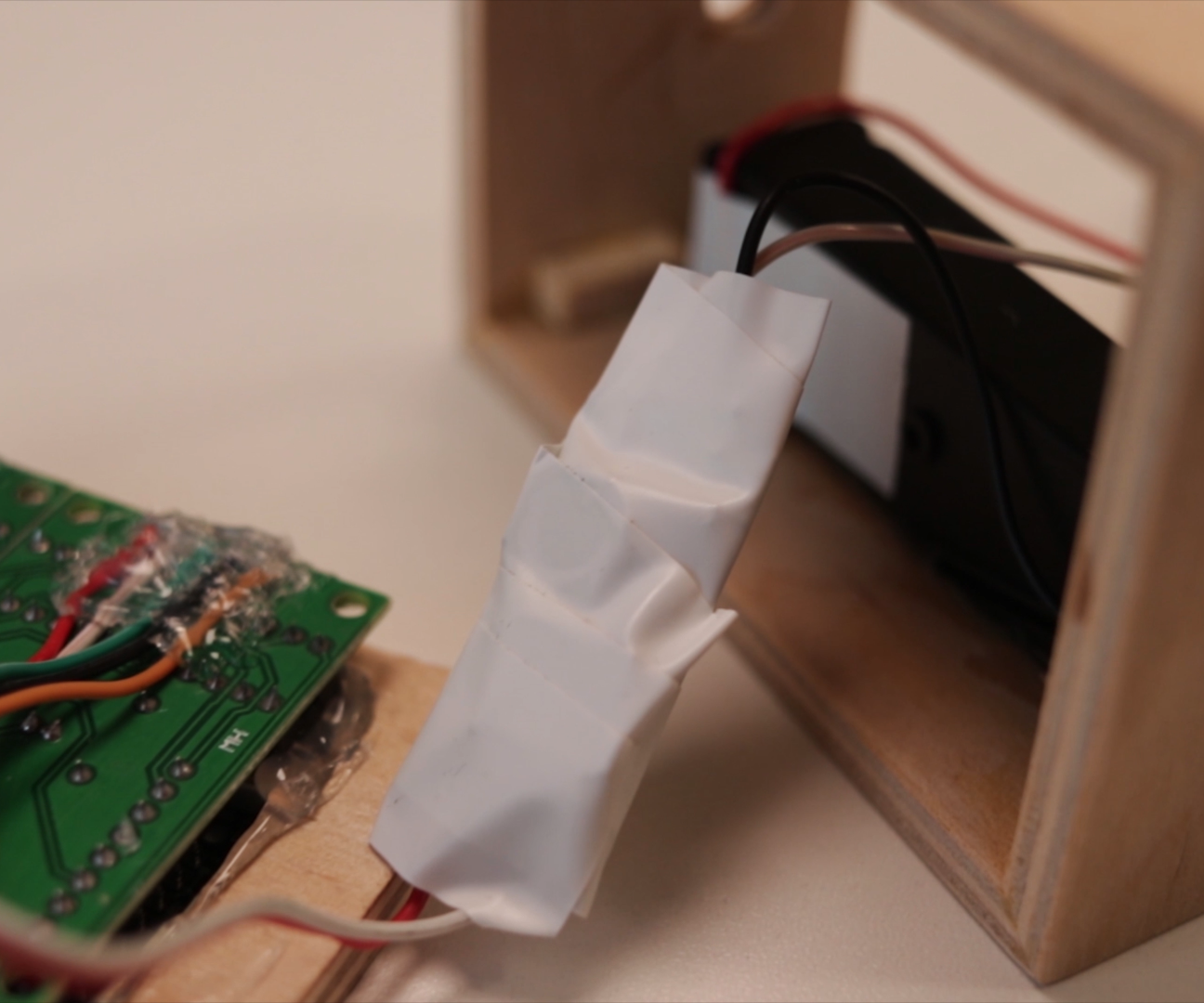


I tested if panel works and it looks good so I wrapped booster module with electrical tape.
I glued one additional wood block which will help to hold Arduino and will be place for the back screw.
Finishing


I made hole for the screw and glued front panel.
Final Touches
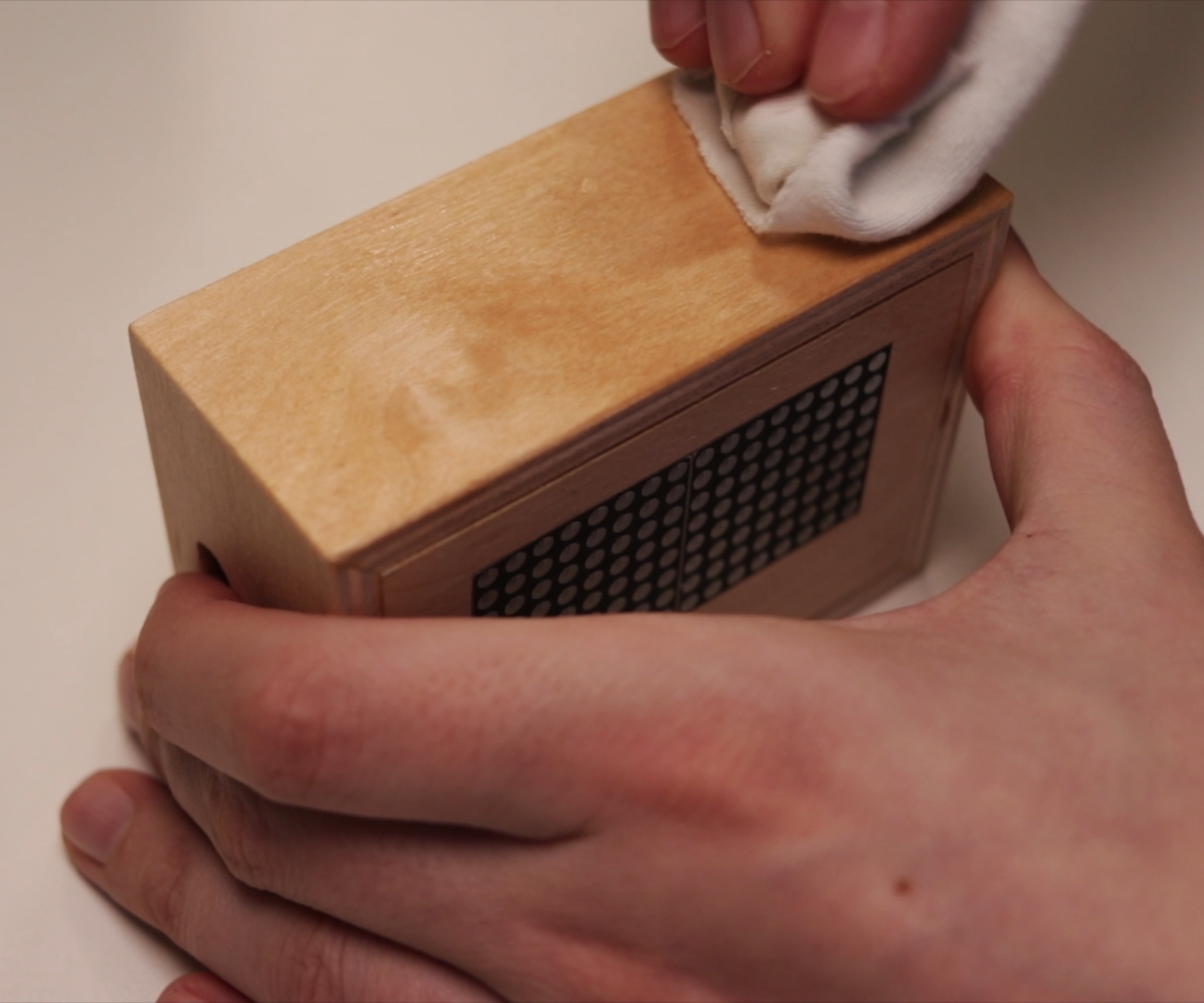


Finally I added some wood oil, attached the back and glued small silicone feet.
END
And that's it - the build is finished!
I hope this instructable / video was useful and informative. If you liked it, you can support me by liking this Instructable / YouTube video and subscribing for more future content. That means a lot!
Feel free to leave any questions about this build.
Thank you, for reading / watching!
Till next time! :)
You can follow me:
- YouTube: https://www.youtube.com/diyperspective
- Instagram: https://www.instagram.com/diyperspective
You can support my work: