Seaside Sweeper - DIY Beach Cleaning Robot
by cu_seaside in Circuits > Robots
2933 Views, 10 Favorites, 0 Comments
Seaside Sweeper - DIY Beach Cleaning Robot

Seaside Sweeper is a Capstone project for CU Boulder's Creative Technology & Design undergraduate program. The design team is made of four team members: Emily Henderson, Alexis Cisneros, Chi Chi Kari, and Ashlyn Duy. This project represents the culmination of research, iteration, and exploration of new technical & creative horizons.
Our love of the oceans inspired us to create a robot that a budding high-school or collegiate electronics enthusiast could attempt and succeed at doing some basic cleaning of their local beach. Existing solutions on the market and in development (respectively) that inspired us included the BeBot and Cornell Nexus - however, we wanted to create something more achievable (both technically and financially!) for DIYers. Thus, the Seaside Sweeper was born. It can operate autonomously or via remote control with over 15 hours of battery life. It costs under $450, is a lot of fun to use (in our opinion!), and leaves plenty of room open for you to tinker & customize it further!
Before we get started, let's answer a common question: isn't 3D printing plastic (which we do often over the course of this project) to clean plastic off beaches ironic and perhaps hypocritical?
PLA and TPU, the two types of filament we use, are both biodegradable and renewable. PLA itself is made from biomass (details) such as sugarcane or corn starch. Furthermore, it can be processed at composting sites or even reclaimed to create recycled PLA. TPU's manufacturing process is a bit more complicated, but it is generally deemed biodegradable within 3-5 years and can be easily reclaimed to create more TPU. With that said, PLEASE do not be throwing the robot in the ocean when you are all done with it! Recycle responsibly!
Supplies
Our focus was on affordability and educational value compared to existing beach cleaning robots on the market. With this focus in mind, the total cost of the project is around $420 with no discounts for the raw materials, but we've found that a lot of these did go on sale during our time working on the project. In addition to the robot and remote control itself, it will be useful to identify a local maker space (like Boulder's BLDG 61) which gives you access to some tools that are needed to put everything together!
Materials:
- Solid Core Wire
- 1 DFRobot Solar Power Manager for 12V Lead Acid Battery*
- 1 12V Lead Acid Battery
- 2 HiLetGo L298N H-Bridges
- 2 HiLetGo nRF24L01+ Wireless Transceiver Modules
- 4 12V DC Motors
- 1 Arduino Mega 2560
- 1 Arduino Uno R3
- 1 Adafruit LIS3MDL Compass Module
- 1 Neo-6M GPS Module
- 1 DS3218 Servo
- 1 1602 LCD Screen with I2C Backpack
- 3 Alligator clips
- 2 KY-023 Joysticks
- 1 roll TPU Filament
- 2 rolls PLA Filament
- 1 Bambu Lab Liquid Glue*
- 1 set of Jumper Wires
- 1 M3 Screw Pack
- 1 pack 100pcs M3 12mm screws
- 1 Mini Breadboard
- 1 ~5Ah, 5-12V LiPo battery (our recommendation)
- If you get that battery, use this XT60 to barrel jack cable to save you some headache.
Tools (not included in total cost):
- Wire stripper
- Wire cutter
- Soldering iron + solder
- Ruler
- Phillips screw driver
- Hex screw driver
- Pliers
- 3D Printer (build plate size Prusa MK4 or equivalent)
- LiPo charger
Total cost at time of writing: $415.75*
Amazon shopping list (*=not on the list, you need to buy direct or through other supplier)
Starting Your Prints (Notes From Our Fabricators)

We recommend starting all the 3D prints first. This step will most likely take the longest, and while your printer is going, you can work on assembling the electronics. The majority of the robot will be printed in PLA, while the tracks will be printed from TPU. There is no particular order in printing that would prevent you from continuing the following steps. When you start printing the tracks for the TPU, you MUST USE GLUE!! TPU, by itself, adheres to the print bed a little too well. A layer of glue will prevent you from destroying your print bed (see above how we discovered this fact).
The glue we recommend is the Bambu Lab liquid glue for easy application and removal, but any 3D printing glue you use will work as well, make sure that you have a good even layer. All the STL files utilized in the project will be found below - in addition, each step of assembly also has the relevant STL files listed in each step. Best of luck!
Downloads
Slicing Your PLA Print

This video is for people who have never printed before or would like a refresher on how to use a 3D printer slicer.
The First Snip(s)


In just a few moments, we are going to be making our first step towards assembling the circuit! We use a DFRobot solar power manager to interface with the battery and provide power to the robot - even though we don't use a solar panel, you are free to add one on top if you want! Our goal here is to connect some wires to one of the output ports on the power manager to provide juice to our motors. In order to do that, we need to prep some wires!
Step Ingredients:
- Solid-core wire (2 colors preferred)
- Wire cutter
- Wire stripper
- Ruler
- Soldering iron + solder
- Phillips screwdriver
You are going to repeat the following wire-prep twice to make a positive set and a negative set:
- Cut an 11 inch and 6.5 inch piece of wire - strip both ends.
- About 2/3 up the longer piece of wire, start another strip but don't actually strip it all the way off, just make a little unstripped section by pushing the insulation towards the end. If you do it right, you will have a little section on the wire that is exposed. Lay the short piece of wire across the exposed piece of the longer piece.
- Twist the shorter piece of wire around the longer piece where they touch, then solder.
- Wrap some electrical/insulating tape around the soldered piece of wire and voilà!
You will now have 2 sets of split wires, with two long ends and 1 short end. Insert the short end of each set into the DFRobot solar power manager's OUT2 port, one in the negative and one in the positive. Using a Phillips screwdriver, screw both the negative and positive screws on the OUT2 port until tight.
Crossing the (H-)bridge


Time to make our first connections! An H-Bridge allows us to arbitrarily reverse DC polarity based on digital data from a microcontroller (in our case, an Arduino Mega 2560) without having to switch wires between positive and negative ports. This means we can arbitrarily reverse the direction of attached DC motors through code! Before we even think about microcontrollers, we need to give our H-Bridge (and, by proxy our motors that will be attached later) a power source so that our robot can move. Let's get started!
Step Ingredients:
- 2 L298N H-Bridges
- Phillips screwdriver
Place the DFRobot power manager on the table with the side with the wires attached pointing away from you. Place a L298N H-Bridge to the left of the solar power manager, ensuring the side with 3 screws in a row faces the wires - if you do this, it makes it super easy to connect the wires! The wire in the DFRobot power manager's positive port goes into the H-Bridge's closest port (of the three ports in a row) to the edge, while the DFRobot's negative port connects to the middle port. Take a look at the upside down view of the H-Bridge to confirm that this means you connected the positive wire to the +12V port and negative wire to the GND port.
PRO TIP: One time, we accidentally got this mixed up and connected the positive wire to the +5V port. We then discovered we fried the H-Bridge and had to use a different one. Be careful!
Feel free to use your Phillips screwdriver to secure the wires you just connected.
Take your other H-Bridge and place it to the right of the DFRobot power manager - again with the 3 screw section facing the wires. This time, put the positive wire into the port furthest away port, and put the negative wire into the middle port like normal. Take a look at the above images of it facing up and upside down to ensure everything is plugged in correctly!
(H-)Bridging the Gap


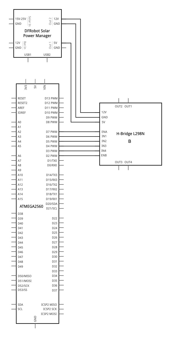
Now that we have our H-Bridges connected to power, we need to be able to send them actual commands from our Arduino Mega.
Step ingredients:
- 12 female-male jumper wires (preferably in 2 ribbons of 6)
- Arduino Mega 2560
Begin by inserting the female ends of a ribbon of female-male jumper wires into both of the H-Bridges. Next, it's time to carefully insert the wires onto the Mega according to the schematics listed above. Notice the H-Bridge we designated as H-Bridge A (it has a little piece of tape that says "A") - it's important that you have the exact same orientation we did for programming reasons! In addition, connect a female-male jumper wire between a 5V port on the solar power manager and insert it into the 5V port on each H-Bridge. Finally, remove the little black jumper next to the 5V port on the H-Bridge - this will help power stabilization later to make everything work correctly!
Let's Roll!


Now that our motor control and power source is all set, let's plug in some motors!
Step ingredients:
- 4 DC motors
- Solid-core wire
- Pliers (optional)
Cut 4 pieces of solid core wire that are roughly 22 inches long and another 4 pieces that are 17 inches long - strip both ends. Two of the motors will have the longer pieces and 2 of the motors will have shorter pieces - it is not 1 short piece and 1 long piece per motor, they will always match. For each motor curl the end through the tiny hole to make a tight loop, pressing with pliers if necessary. Then, solder the connections.
Houston, We Have (half) Contact


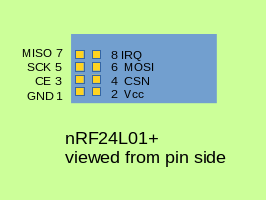
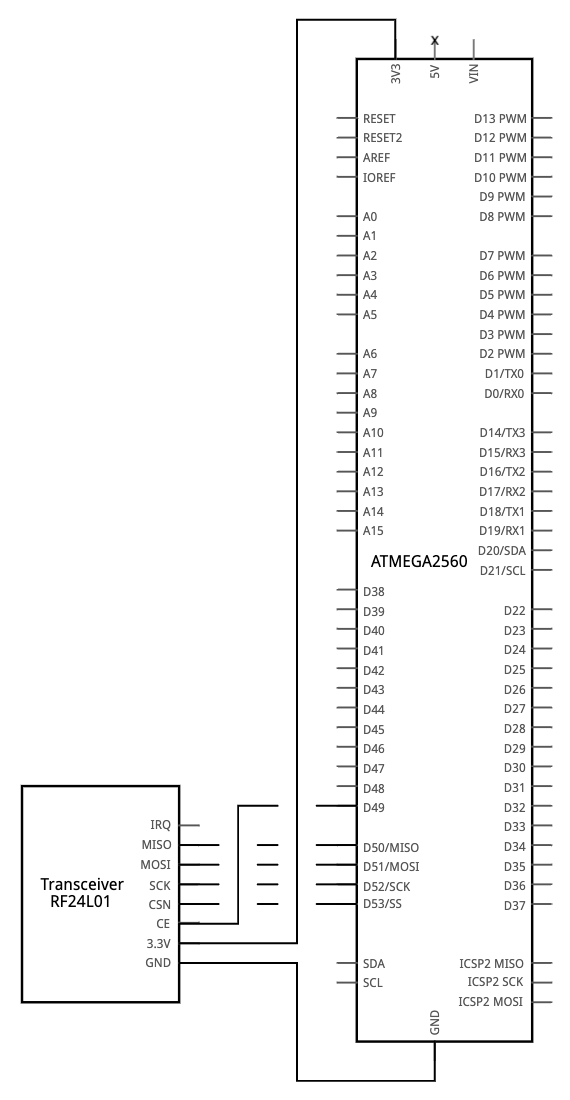

It's time to prepare the Mega to receive RF signals! In general, we highly recommend the tutorial from Robin2 on the Arduino forums which is incredibly in-depth regarding the use of the nRF24L01+ module that we use. Full credits & thanks to them for the pin side image!
Step ingredients:
- nRF24L01+ module (recommended with no power amplifier module)
- Arduino Mega 2560
- 7 female-male jumper wires (preferably in a ribbon)
Place the jumper wires into every available pin on the nRF24 module except IRQ (we just don't need it!). Then, VERY CAREFULLY follow the schematic provided - it is very easy to mix them up. After this, our robot is now ready to receive RF signals from the remote control!
PRO TIP: We accidentally plugged a +5V power source into the nRF24 module once... luckily we had a few extra. Please ensure you are using a +3.3V power source from the Mega!
Speaking of Remote Control...


Let's make a remote control to move our robot manually!
Step ingredients:
- Arduino Uno
- nRF24L01+ module (recommended with no power amplifier module)
- 7 female-male wires
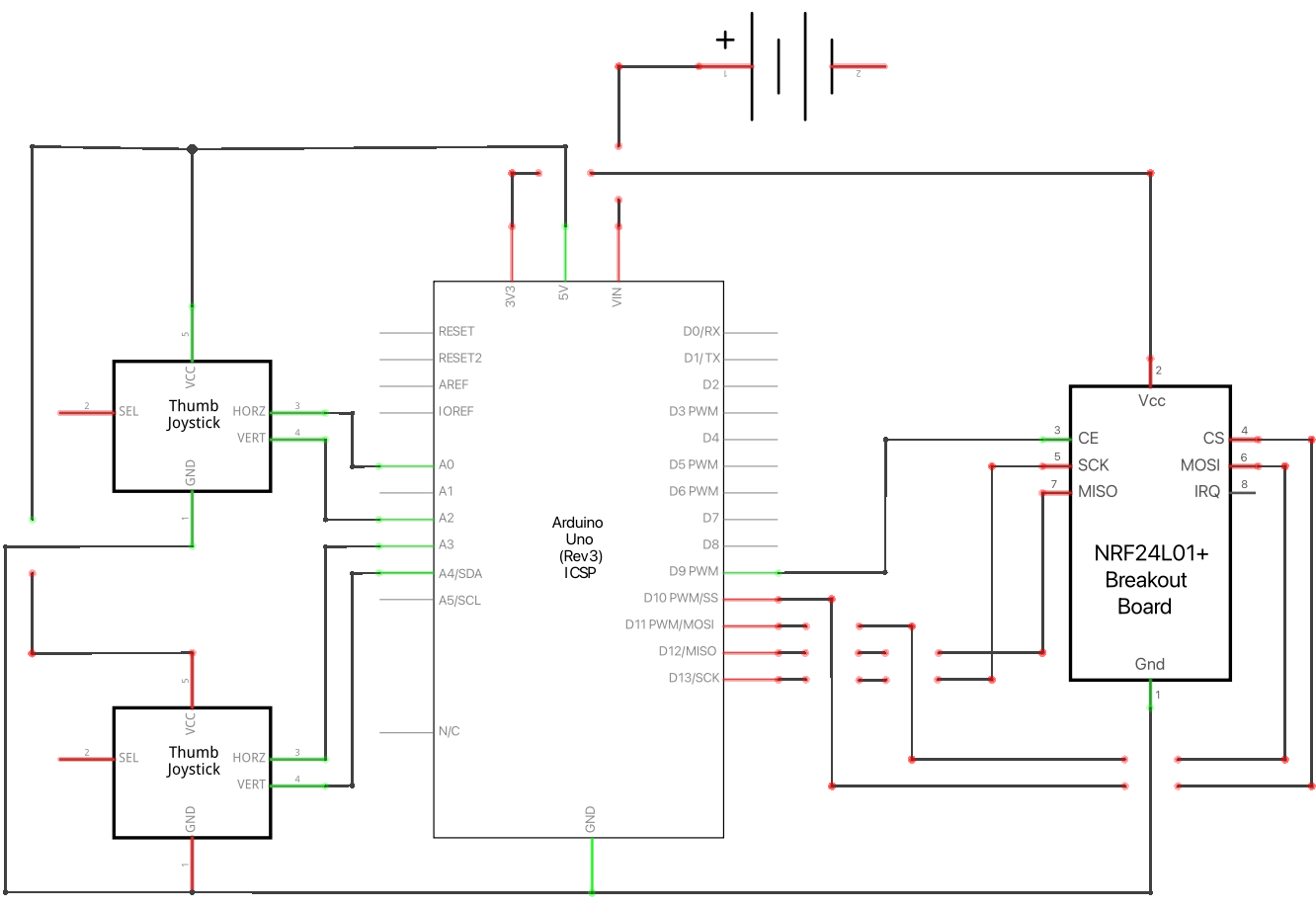
We are going to do a very similar setup to adding RF capabilities to the robot, we just the ribbon to the Uno on different pins. Borrowing again from Robin2's excellent blog post, follow the schematic to precisely wire the RF24 module to the RC Uno.
Note: In the above "after plugging in" picture you'll see a joystick in the background. Ignore that for now! It's coming up :)
Houston, We Have Contact
.png)


.JPG)
.JPG)
We now have the capability to send signals to our robot! But, what we're missing is some actual data to send. Let's use 2 joysticks, 1 to control the movement of the robot (foward, backward, left, right) and 1 to control the position of the scoop (up & down).
Step ingredients:
- Arduino Uno (from last step)
- 2 KY-023 joysticks
- Female-male & male-male jumper wires (exact number is dependent on what you need)
- Optional (based on what you do)
- Small breakout board
- Solder & soldering iron
- Hot glue
You'll see in the schematic that both joysticks have a shared ground and a shared +5V power source - you may have also noticed that the Uno only has 1 +5V output! This means you will have to construct some sort of power/ground sharing mechanism.
We decided to accomplish this by using a very tiny breakout board piece and soldering 6 jumper wires in 2 lines of 3 wires (each line had 2 female-male wires to go to the joysticks and 1 male-male wire to go to the Uno) each. After hot-gluing, we had an electrically insulated power sharing breakout board! You could also accomplish this with a tiny breadboard or some other method, it's entirely up to you.
After the power is figured out, follow the schematic to plug in the joysticks. If all goes according to plan, the RC circuit is now complete!
Assemble the Remote
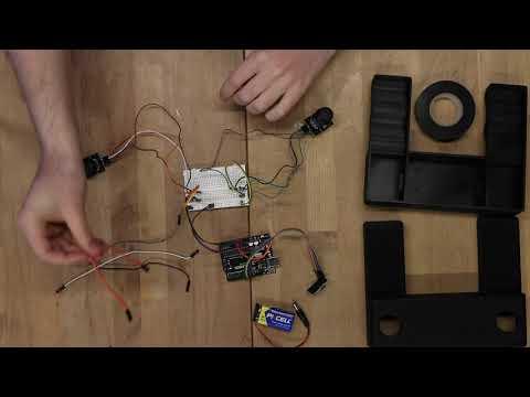
Load the controller program onto the Uno before proceeding with assembly (also, always a good idea to test the circuit works! You will need the RF24 library. The serial monitor feed will give you a warning if you wired something incorrectly). Place the Uno at the bottom of the controller bed. Using electrical tape, affix the joysticks in place through their holes and then seal the remote itself with some more electrical tape. Easy DIY controller complete!
Finding the Way


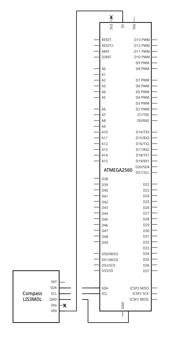

It's time to give our robot some navigation skills! By default, when it is not receiving an RF signal, the robot will travel to a pre-calculated starting point within the set coordinates and will begin scooping up trash. In order to navigate its bounds accurately, we need to give it the ability to locate itself via GPS and keep itself on-course with a compass.
Step ingredients:
- Neo-6M GPS module
- Adafruit LIS3MDL compass module
- 12 male-male jumper wires
- Small breadboard
- Arduino Mega (previous step)
Begin by placing the compass and GPS modules next to each other on the small breadboard oriented horizontally. Both of the modules require a common +5V power source and ground. Thus, we begin by using some jumper wires (short, if you have some) to link both of the modules' VIN and GND pins to one another in parallel. Next, use some additional jumper cables to link each of the data pins to the breadboard. Follow the schematic to make the connections!
Let There Be L(CD)ight

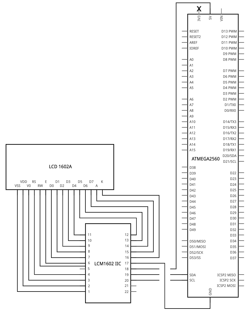

Let's add an LCD screen so that our robot can inform us if something's wrong, if it's sad (something's wired wrong or it's missing GPS signal or something else), or if it's happy.
Step ingredients:
- 1602A LCD screen with I2C backpack
- 4 female-male jumper wires
Place the 4 wires on the I2C backpack and connect according to the schematic! This one's pretty simple.
Note: With the I2C backpack, you can use a Phillips screwdriver to adjust the contrast - could be handy to know!
Electronics Reflection

Great work so far! Take a look at a time lapse of us putting together the electronics ourselves - we're right there with you! The hardest part is done - now it's time for assembly.
Assembly Begins! Motor Casing Time

Step ingredients:
- 4 motor casings (2 of each variant)
- 4 motor doors
- 12 M3 screws
Begin by placing each motor in a motor casing. Once you do, use 3 M3 screws to secure the motor in place through the designated holes in the casing. Next, while being careful to not disconnect the soldered wires, poke the wires up and through the larger hole on the top of the casing. Finally, slide the motor door over the exposed motor wire points to keep everything safe and sound! Check out the above video on how to complete 1 motor.
Bridging the Gap (between Motors)
 Gap)
In order to make sure our motors are aligned, we have implemented some brackets between them to keep them in line!
Step ingredients:
- 24 M3 Screws
- 2 short brackets
- 2 long brackets
Orient the completed motor casings such that you have two pairs, with the stub containing the 3 holes along the length of the casing facing each other on the outside (make sure the wires are facing upwards!). Next, get your screwdriver and screws handy! Screw in the brackets as seen in the above video - short brackets go between the short stubs sticking out perpendicularly, while the long brackets connect between the other sets of stubs.
Build Me Up, Sifter Layer!
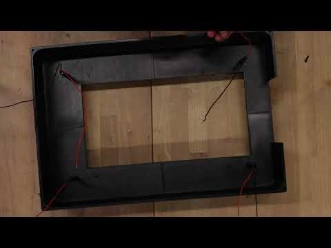
Now that we have our motors all connected, let's add the first layer to our Seaside Sweeper: the Sifter Layer! This layer will hold the sifter basket that stores our trash when it gets picked up.
Step Ingredients:
- 12 M3 Screws
- Superglue (or other bonding agent)
First, assemble the sifter layer by gluing or otherwise adhering the four pieces together. They only fit together one way, so it won't be too tough to figure out how they connect! Once everything is together, pull the wires up and through the sifter layer tubes and gently push the assembled layer down onto the motors. Check around the sides to make sure the sifter layer is flush with the motors. Next, use 1 screw on each piece of the sifter layer to initially screw in each piece to 1 motor - this will make sure all other screws on all other pieces align later. After this is done, finishing screwing the sifter layer in to the motors to complete this step!
Scoop
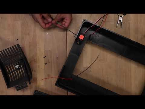
Let's add the most essential part of the Seaside Sweeper: the scoop!
Step Ingredients:
- 9 M3 screws
- 1 DS3218 270° Servo
Begin by pushing the scoop hinge bit into the scoop hinge so that it forms one piece. Next, attach the long arm to the stub at the bottom of the scoop, using a single screw to secure it. In addition, press-fit the small metal arm that came with the servo into the short arm for later. Now it's time to attach the servo to its bracket! Take the servo bracket and servo, affixing the bracket to one side of the servo and screwing two screws in on the top and bottom. Attach the completed servo assembly to the four holes along the sifter layer wall, ensuring that the spoke is facing towards the opening. Next, attach the scoop/scoop-hinge combo underneath the sifter layer opening, using two screws to secure it in place. Finally, put the short arm/metal arm combo onto the servo and connect the long arm by pressing the long arm into the short arm, using the washer on the other side to secure it in place. Our scoop is now all done!
Adding the Exterior, Interior, and Electronics Layer

.gif)

.jpeg)
Now let's add the outside!
Step Ingredients:
- 180 M3 Screws
- Superglue
- 1 roll of TPU
Tracks:
- It's time to put that TPU to use! Arrange as many single tracks as you can on the MK4 printer during slicing - you're going to need 90 of them (don't forget to use the Bambu glue on the build plate as mentioned in the intro)! After they're all printed, clear out the tiny spaces of supports in each piece, then merge them together in a track-like fashion. 1 screw on either side of each track connection will connect them (hence the 180 screws).
For the basket, use superglue to attach all the pieces together. Once you've done that, drop it in the huge basket-shaped slot at the bottom of the robot! Next, attach the wheels to each motor. Make sure to orient them to attach correctly (there's a flat portion on each wheel connector that corresponds to a flat portion on the motor spoke). Next, wrap the tracks around each set of wheels to attach them to the wheels - see the GIF to see how to lay it out and assemble. Finally, assemble the electronics layer like the sifter layer - each piece will fit into one another and adhere with sifter glue. Place the completed layer on top of the sifter layer, pulling the wires through the holes. Ensure to orient this layer such that the part with the small rectangular slot is above the servo and ensure to pull the servo wire up as well. Whew! Almost done!
Note: We would like to thank user wh1t3shad0w for the track STL, which was released under Creative Commons - Attribution license.
Finale
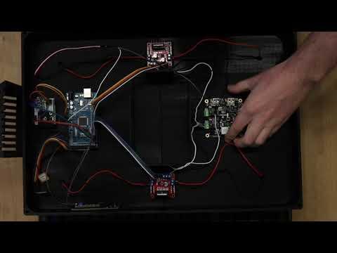


Time for final assembly!
Step ingredients:
- Superglue
Assemble the lid by connecting the pieces (they only connect one way!) and super-gluing them together. Set to the side while you take hold of all the electronics! Place the electronics into their respective slots as seen in the video - all pieces have a special place on the electronics layer. Once everything is in its place, screw the motor wires into the H-bridge side terminals as seen (make a reflection, such that if one side is red on top, black on bottom, the other side is the opposite).
The last step is to load the code for the robot onto the Seaside Sweeper! You'll need the following libraries:
- TinyGPSPlus
- Adafruit LIS3MDL
- RF24
- LiquidCrystal_I2C
- Servo.h
If you want to use the GPS mode (it's a bit experimental, feel free to tinker with the additional functions provided!), use Google/Apple Maps to get some Longitude/Latitude coordinates and plug them into the right #defines at the top of the program! The LCD screen and serial monitor will both give you warnings or indications if something isn't plugged in correctly or is missing, be sure to leverage that early before sealing it all up!
Assembly Reflection

Look at how far you've come! We're right there with you - there's only a little wrap-up left!
Wrap-up

.png)
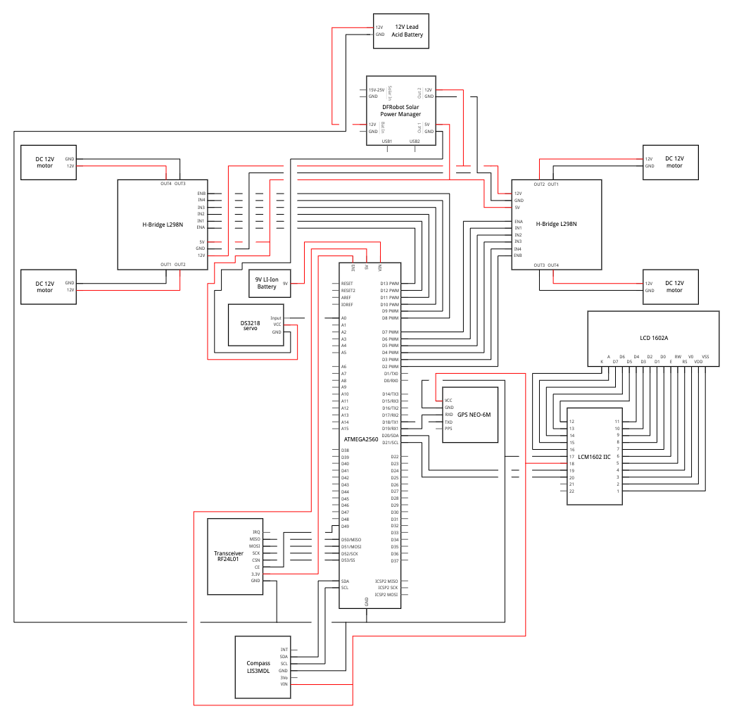
To ensure electronics reliability, we added an additional power source (LiPo battery) for the Arduino Mega.
Step Ingredients:
- LiPo battery
- XT60 connector (optional, depending on battery)
- 1 alligator clip
Connect the LiPo battery to the Arduino barrel jack using a connector when you're ready to take the robot for a spin! In addition, also make sure to connect a shared ground between the battery and the Mega - we used an alligator clip to accomplish this.
Enjoy Your New Seaside Sweeper!

Thanks so much for being on this journey with us! We hope you enjoy using your new Seaside Sweeper - most of all, we hope you improve it in some way and share it with the world.