9 Arduino Tutorials for Grove Starter KIT From Seeed Studio
by Ardumotive_com in Circuits > Arduino
16031 Views, 23 Favorites, 0 Comments
9 Arduino Tutorials for Grove Starter KIT From Seeed Studio

Grove is a modular electronic platform for quick prototyping. Every module has one function, such as touch sensing, creating audio effect and so on. Just plug the modules you need to the base Arduino shield, then you are ready to test your idea buds.
This Grove - Starter Kit for Arduino is a perfect starter kit for Arduino begginers. It includes a Base Shield which have many Grove connectors on board, twelve Grove modules that covers most functions needed by a beginner and a very helpful user manual that can help get started quickly.
You can buy if directly from Seeed Studio from here: https://www.seeedstudio.com/Grove-Starter-Kit-for...
Tutorial updates can also be found here: https://www.ardumotive.com/tutorials.html
Video Presentation
What Is in the Box?


In the box you will find:
- Grove Arduino Shield
- Grove LCD I2C with RGB Backlight
- Grove Smart Relay
- Grove Buzzer
- Grove Sound Sensor
- Grove Touch Sensor
- Grove Rotary Angle Sensor
- Grove Temperature Sensor
- Grove LED
- Grove Light Sensor
- Grove Button
- One blue LED
- One green LED
- One red LED
- A mini servo motor
- Some Grove cables
- A 9V to Barrel Jack Adapter
- A typical manual
In this guide you will also find and a tutorial for the BME280 Barometer sensor, you can buy is separately from here: https://www.seeedstudio.com/Grove-Temp-Humi-Barom...
You will also need an Arduino board, we will use the popular Arduino UNO.
Let's get started!
1st Tutorial: LED Socket Kit


Grove - LED is designed for the beginners of Arduino/Seeeduino to monitor controls from digital ports. It can be mounted to the surface of your box or desk easily and used as pilot lamp for power or signal. Its brightness can be adjust by potentiometer.
Tutorial updates can be found here: https://www.ardumotive.com/led-socket-kit-en.html
Features
- Grove compatible interface
- 3.3V/5V Compatible
- Adjustable LED orientation
- Adjustable LED brightness
About code:
Keep in mind that setup( ) routine runs only once after power on / re-program or press the reset button. In the program below, the first thing you do is to initialize pin 2 as an output pin with pinMode( ) function in setup( ) routine.
The loop( ) routine runs over and over again, forever. In the main loop, you turn on or off LED with digitalWrite( ) function and "pause" the program for three seconds with delay( ) function. (1 sec is 1000 ms)
About LEDs:
Common leds have two pins. The positive end of a led (larger pin) is called anode, and the negative end is called cathode.The Arduino uno board have a built-in LED on pin 13, but in this tutorial we are going to be adding our own on digital pin 2.
Downloads
2nd Tutorial: Buzzer


The Grove- Buzzer module has a piezo buzzer as the main component. The piezo can be connected to digital outputs, and will emit a tone when the output is HIGH. Alternatively, it can be connected to an analog pulse-width modulation output to generate various tones and effects.
Features
- Easy to use piezoelectric buzzer
- Uses Standard 4-pin Grove Cables to connect to other Grove modules such as - Grove Power Modules and Grove - Base Shield
Tutorial updates can be found here: https://www.ardumotive.com/buzzer-en.html
About the code:
The code is similar with the LED code. Now, try to use the tone() function:
tone(6, 1000); // Send 1KHz sound signal... and to stop the tone noTone(6);
How it works? It's simple, tone(6, 1000) sends a 1KHz sound signal to pin 6, delay(1000) pause the program for one second and noTone(buzzer) stops the signal sound. The loop() routine will make this run again and again making a short beeping sound.
About the buzzer:
A buzzer or beeper is an audio signalling device, which may be mechanical, electro-mechanical, or piezoelectric (piezo for short). Typical uses of buzzers and beepers include alarm devices, timers, and confirmation of user input such as a mouse click or keystroke. Buzzers have pollarity, one pin is connected to signal and another (the smaller) to gnd.
Downloads
3rd Tutorial: Button With Buzzer
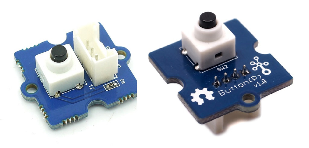


Grove - Button is a momentary push button. It contains one independent "momentary on/off" button. “Momentary” means that the button rebounds on its own after it is released. The button outputs a HIGH signal when pressed, and LOW when released. The Sig marked on silk layer stands for signal while NC stands for not used at all. There are two versions of this button available as showed in the pictures. The only difference is the direction of the Grove socket.
Features
- Easy to use momentary ON/OFF button
- Uses Standard 4-pin Grove Cables
Tutorial updates can be found here: https://www.ardumotive.com/button-with-buzzer-en....
For this project we will also connect to the Grove Shield a buzzer.
About the code:
We will use the digitalRead() function to read the state of the button that is connected in digital port 2. With if statment we compare the state of the buzzon that can be HIGH when is pressed and LOW in normal position Try it!
Downloads
4th Tutorial: Rotary Angle Sensor

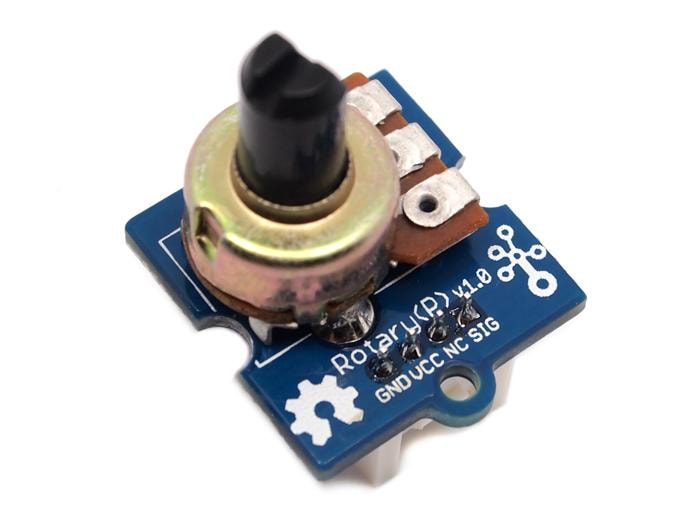


The rotary angle sensor produces analog output between 0 and Vcc (5V DC with Seeeduino) on its D1 connector. The D2 connector is not used. The angular range is 300 degrees with a linear change in value. The resistance value is 10k ohms, perfect for Arduino use. This may also be known as a “potentiometer ”. There is another product, Grove - Rotary Angle Sensor(P). What does “P” mean? “P” is for “panel mount” in this product.It is the sister version of Grove - Rotary Angle Sensor. They are identical except the Grove connecter is moved to the back so that you can easily use it as a neat and wire-free human interface device.
Tutorial updates can be found here: https://www.ardumotive.com/rotary-angle-sensor-en...
For this tutorial we will need:
- Arduino UNO
- Grove Base Shield
- Rotary Angle Sensor
- LED (Connect Grove-LED to D3 port of Grove-Base Shield)
Downloads
5th Tutorial: LCD RGB Backlight With Temp Sensor
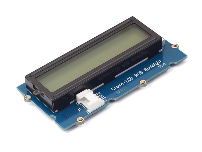
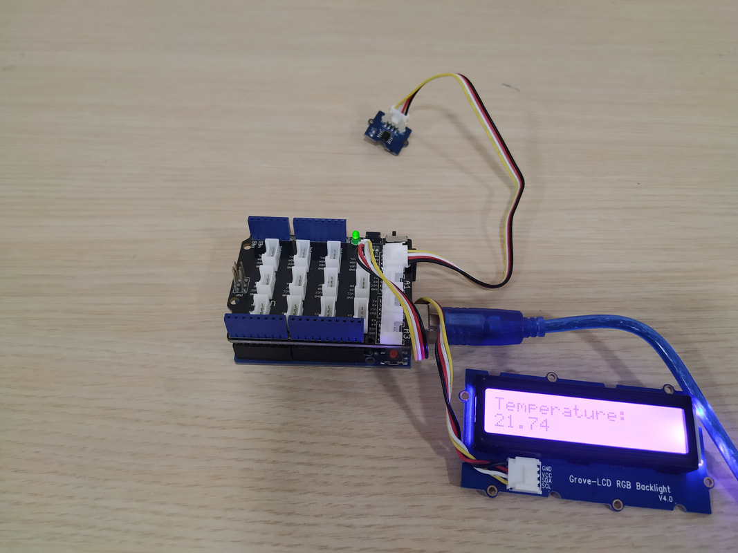

This Grove enables you to set the color to whatever you like via the simple and concise Grove interface. It takes I2C as communication method with your microcontroller. So number of pins required for data exchange and backlight control shrinks from ~10 to 2, relieving IOs for other challenging tasks. Besides, Grove - LCD RGB Backlight supports user-defined characters. Want to get a love heart or some other foreign characters? Just take advantage of this feature and design it! This product is a replacement of Grove - Serial LCD. If you are looking for primitive 16x2 LCD modules, we have green yellow backlight version and blue backlight version on sale also.
Features
- RGB Backlight
- I2C communication
- Built-in English fonts
- 16x2 LCD
Tutorial updates can be found here: https://www.ardumotive.com/lcd-rgb-backlight-with...
Grove - Temperature Sensor uses a thermistor to measure ambient temperature. The resistance of thermistor changes based on ambient temperature. This resistance value alters the output of a voltage divider which is measured by an analog input pin and converted to a temperature value. The operating range is -40 to 125°C , with an accuracy of 1.5°C .
For this tutorial we will need:
- Arduino UNO
- Grove Base Shield
- LCD RGB Backlight
- Temperature Sensor (Connect Grove-Temp sensor to A0 port of Grove-Base Shield)
6th Tutorial: Touch Sensor With LED


Grove - Touch Sensor enables you to replace press with touch. It can detect the change in capacitance when a finger is near by. That means no matter your finger directly touches the pad or just stays close to the pad, Grove - Touch Sensor would outputs HIGH also.
Tutorial updates can be found here: https://www.ardumotive.com/touch-sensor-with-lede...
Downloads
7th Turorial: Sound Sensor


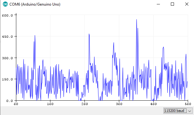

Grove - Sound Sensor can detect the sound intensity of the environment. The main component of the module is a simple microphone, which is based on the LM386 amplifier and an electret microphone. This module's output is analog and can be easily sampled and tested by a Seeeduino.
Features
- Easy to use
- Provides analog output signal
- Easily integrates with Logic modules on the input side of Grove circuits
Tutorial updates can be found here: https://www.ardumotive.com/sound-sensor-en.html
Downloads
8th Tutorial: Barometer Sensor (BME 280)
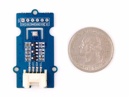


Grove - Temp&Humi&Barometer Sensor (BME280) is a breakout board for Bosch BMP280 high-precision, low-power combined humidity, pressure, and temperature sensor. This module can be used to measure temperature, atmospheric pressure and humidity accurately and fast. As the atmospheric pressure changes with altitude, it can also measure approximate altitude of a place. It can be connected to a microcontroller with I2C (integrated with Grove socket) or through SPI bus. We have also provided highly abstracted library to make this more product easier to use.
Tutorial updates can be found here: https://www.ardumotive.com/barometer-sensor-bme-2...
Downloads
9th Tutorial: Light Sensor
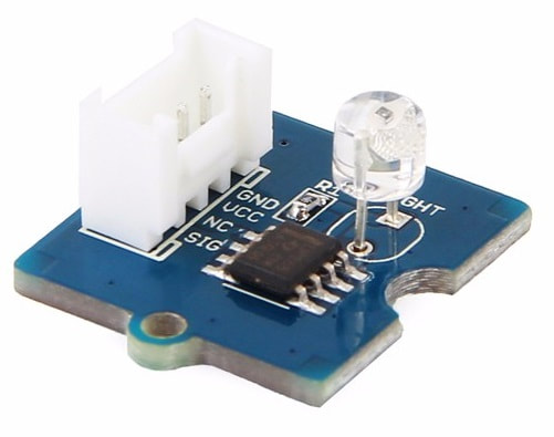


The Grove - Light sensor integrates a photo-resistor(light dependent resistor) to detect the intensity of light. The resistance of photo-resistor decreases when the intensity of light increases. A dual OpAmp chip LM358 on board produces voltage corresponding to intensity of light(i.e. based on resistance value). The output signal is analog value, the brighter the light is, the larger the value.
This module can be used to build a light controlled switch i.e. switch off lights during day time and switch on lights during night time.
Tutorial updates can be found here: https://www.ardumotive.com/light-sensor-en.html
Downloads
Well Done!
You have successfully completed an Arduino Grove tutorial.
I hope you liked this, let me know in the comments.