Self Driving Car Using Machine Learning and PID Controller
by GuillenG in Circuits > Arduino
120 Views, 1 Favorites, 0 Comments
Self Driving Car Using Machine Learning and PID Controller
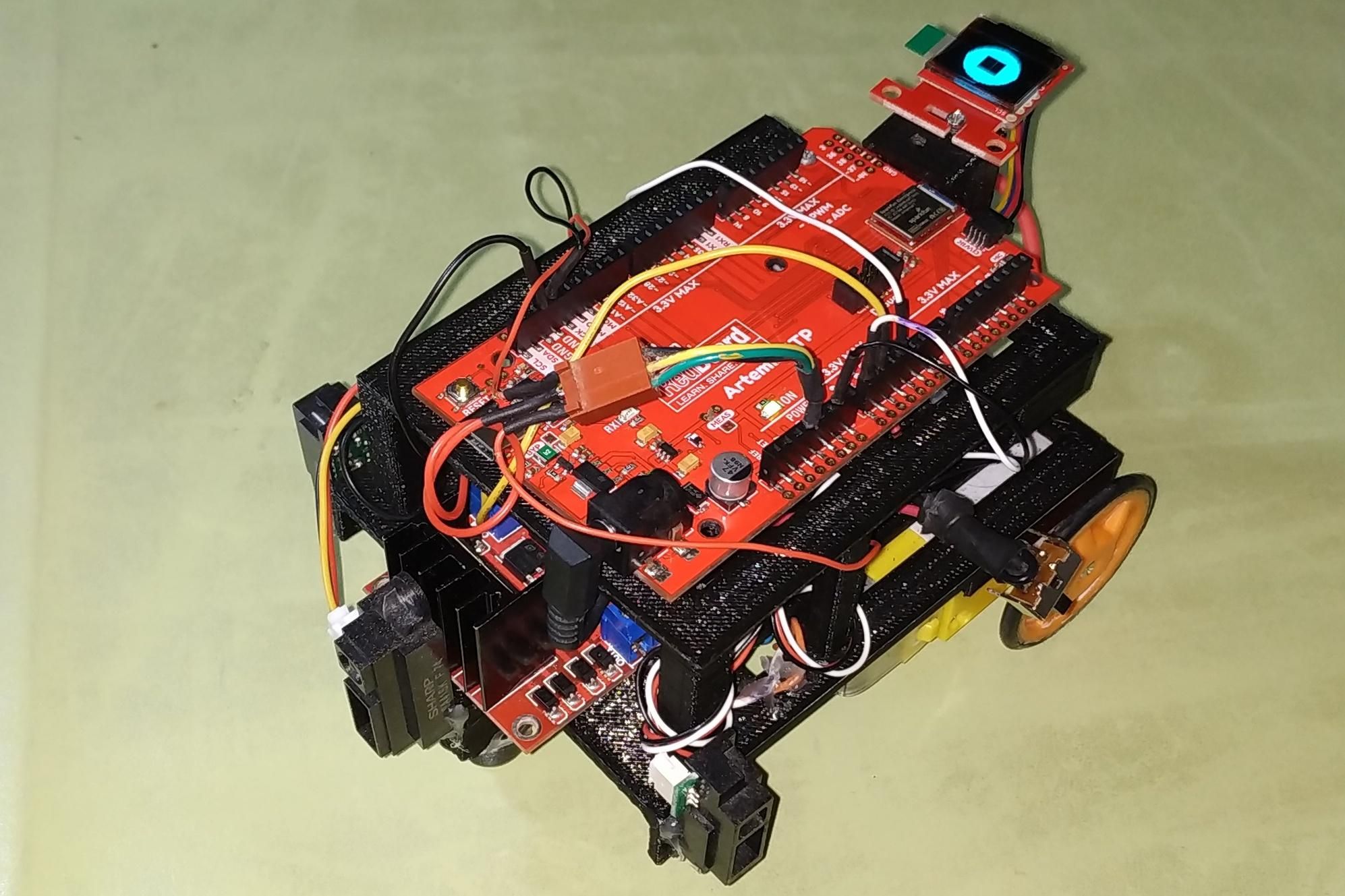
Machine learning and PID controller allow us to control an autonomous car to drive around an object.
This project has two goals that I explain in more detail in later sections.:
- Machine Learning will allow us to use Neural Networks so that our "Redboard Artemis ATP Car" drives autonomously and makes decisions at the nodes: turn left or right, move forward and backward: https://en.wikipedia.org/wiki/Machine_learning
- The PID Controller allows us to automatically center the car along the way, and using infrared distance sensors: https://en.wikipedia.org/wiki/PID_controller
The goals of this project are the following:
- Apply the machine learning to a robot car.
- Add the PID controller to this robot.
- Finally, add the Micro OLED Breakout device to this robot.
To facilitate the understanding of this project, we have divided it into the following sections: Hardware, Machine Learning, PID Controller, Adding the micro OLED Breakout, Printing and Assembling the Chassis, and Conclusion.
Supplies
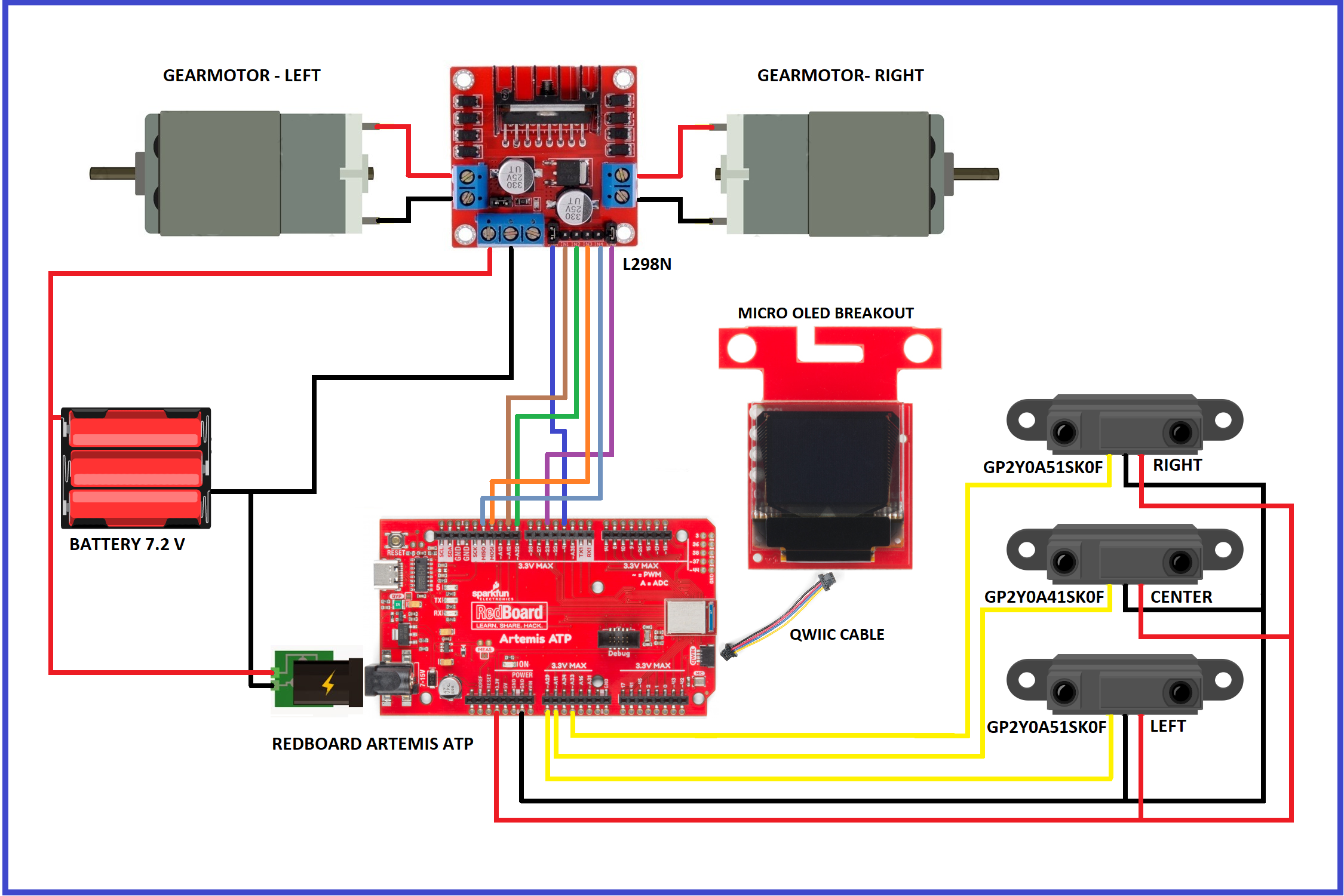
Hardware:
- SparkFun RedBoard Artemis ATP × 1
- SparkFun Micro OLED Breakout × 1
- SparkFun Full-Bridge Motor Driver Breakout - L298N × 1
- SparkFun Qwiic Cable Kit × 1
- Ni-MH 2/3A 1100mAh 7.2V × 1
- IR Distance Sensor × 3
- Gearmotor 120 rpm (generic) × 2
- Ball caster × 1
Software:
- Arduino IDE
- Python 3.7.3
Hand Tools:
- 3D Printer
Printing the Chassis
There are two pieces that must be printed with PLA plastic. They may have to adjust the measurements somewhat, or file the plastic a little so that everything fits well. The 3D files you can get on the download section: IMAGE 1 and IMAGE 2
Assembling the Chassis
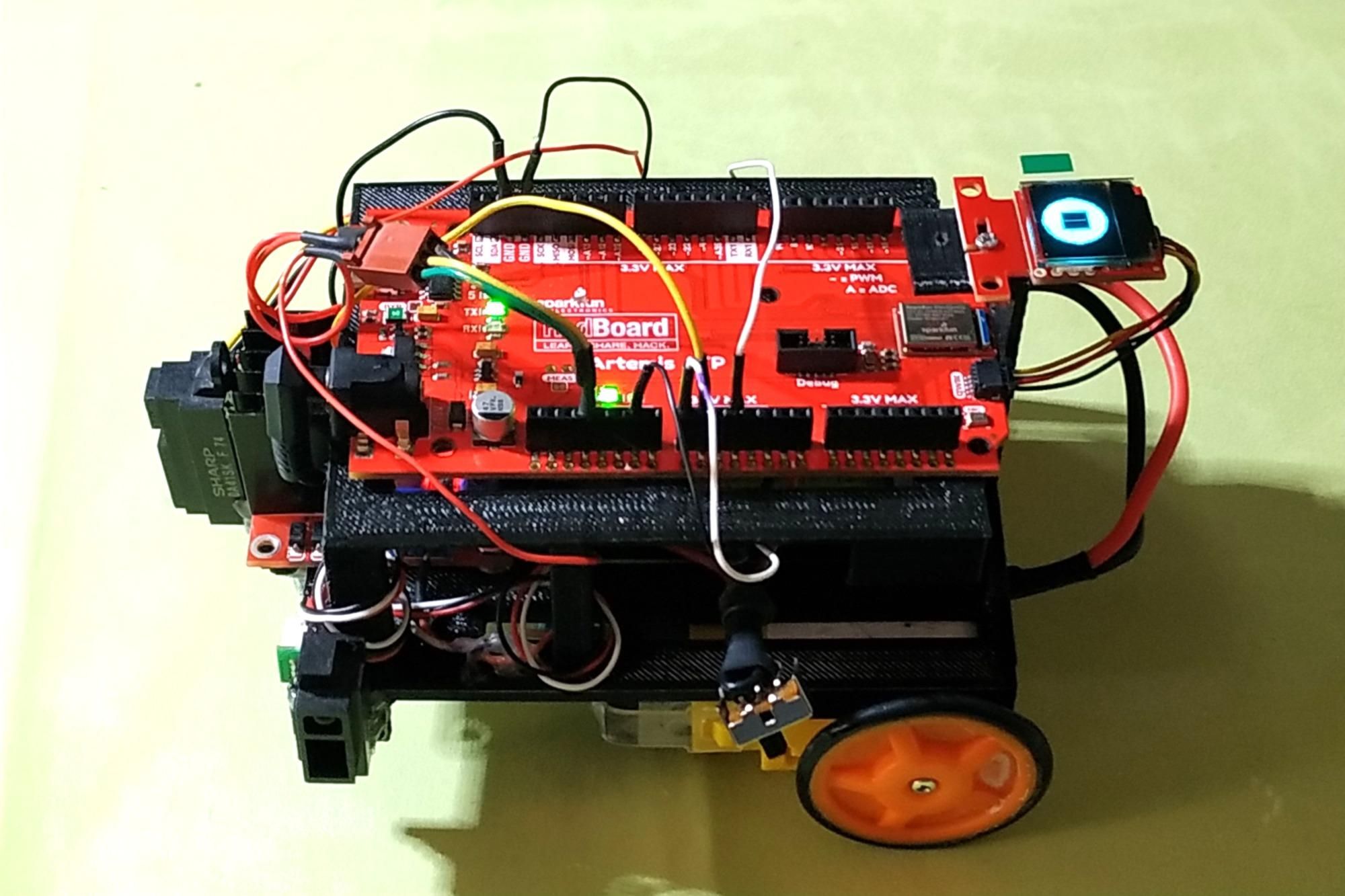
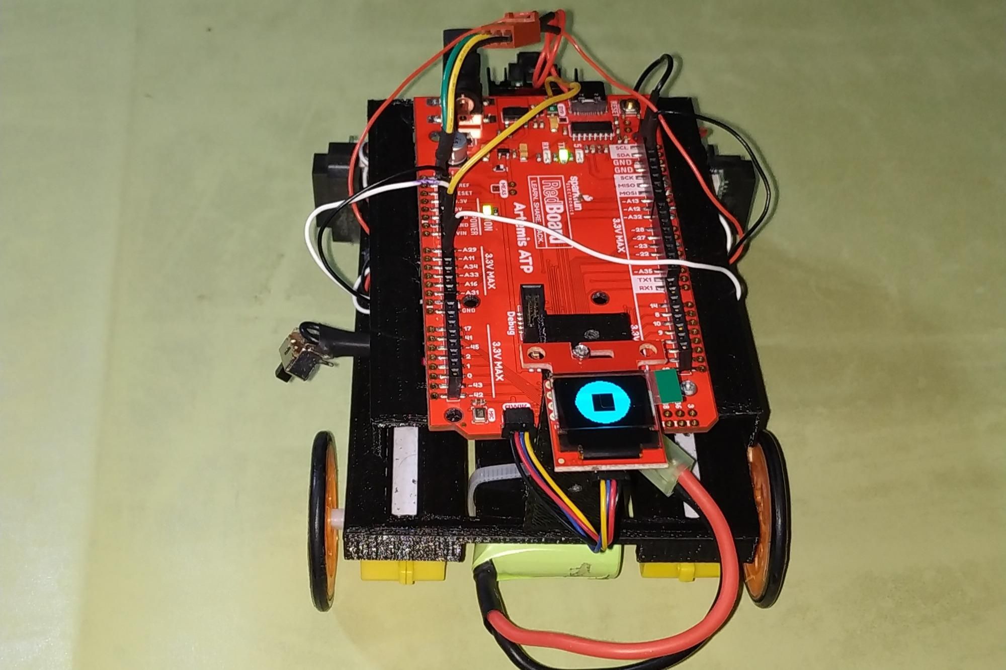
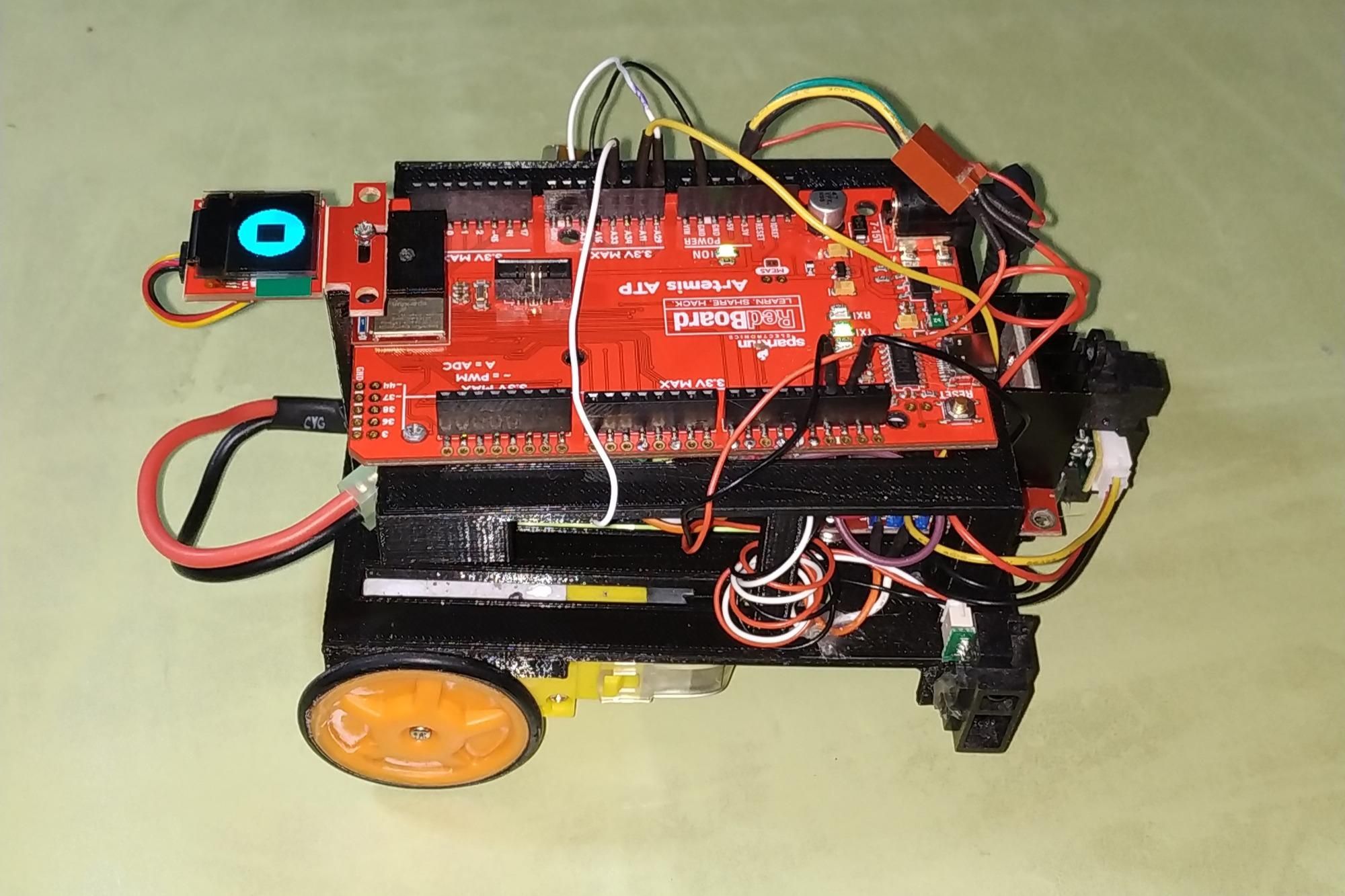
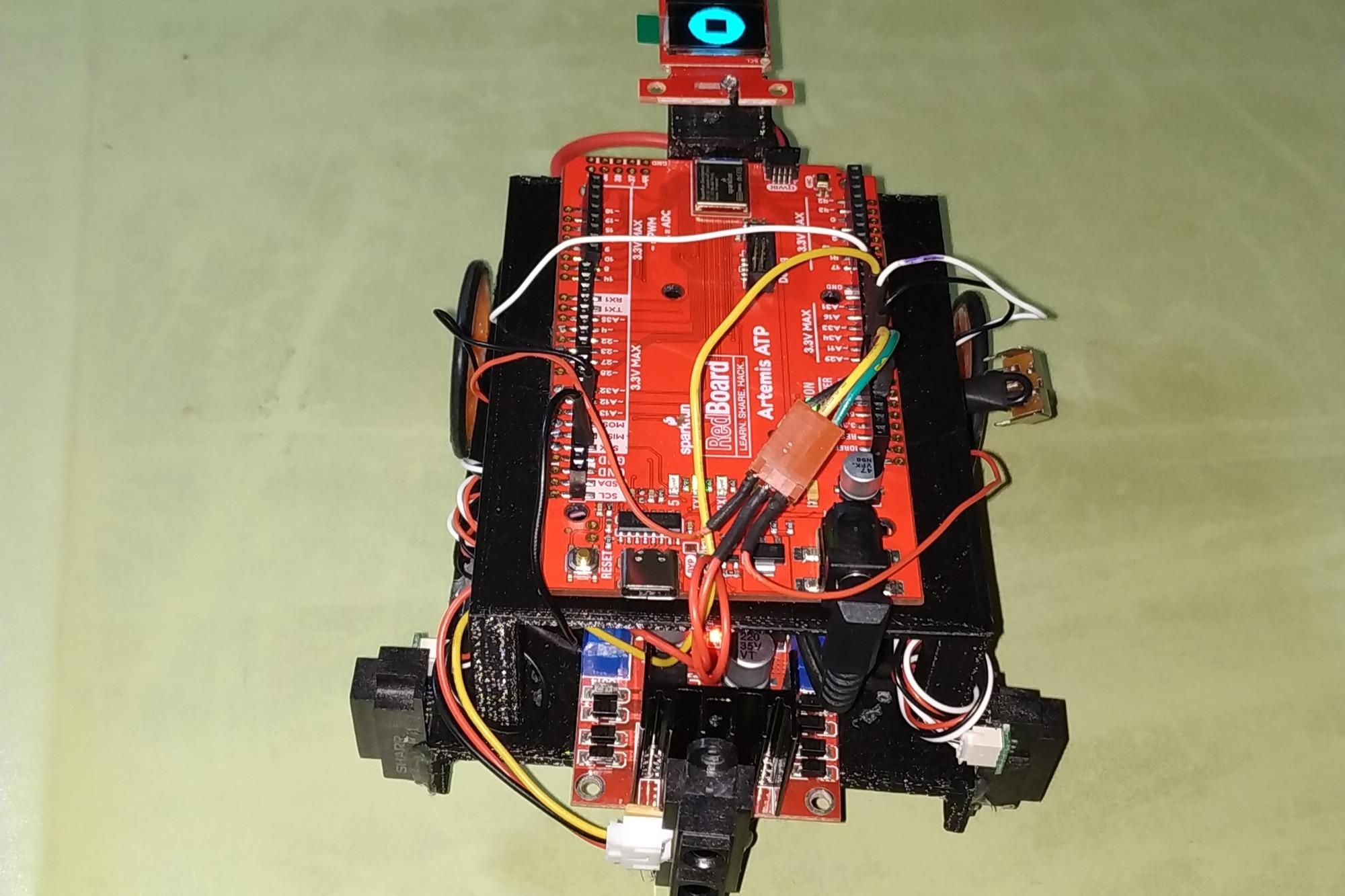
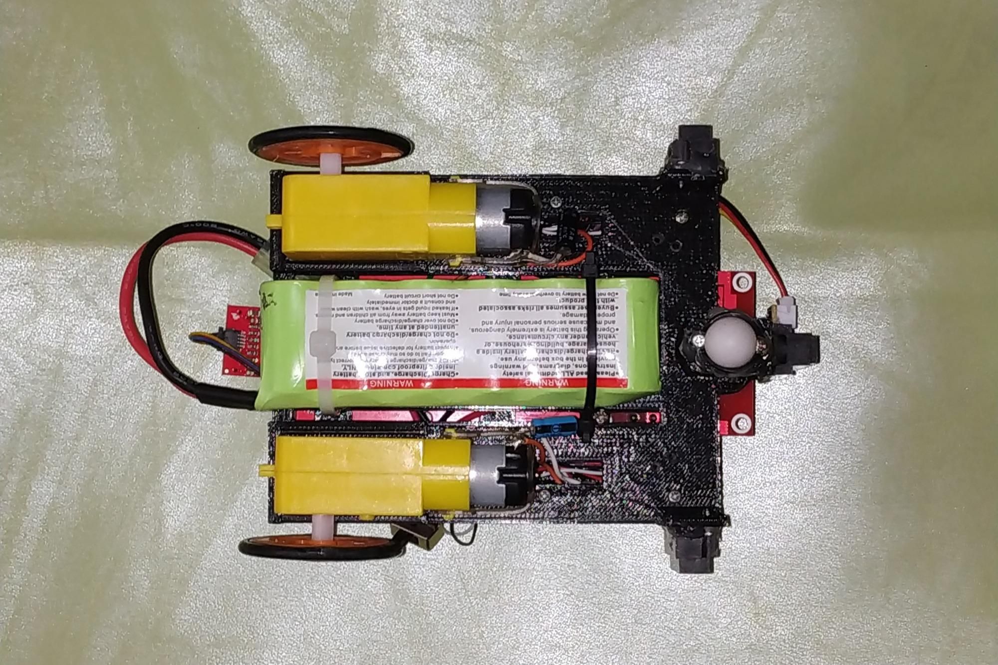
On the chassis bottom, you have to place the next devices:
- The gearmotors are adjust with plastic gauze;
- The GP2Y0A51SK0F infrared sensors are placed with screws on the left and right front ends of the chassis;
- The GP2Y0A41SK0F infrared sensor is placed with screws in the center and front of the chassis;
- The battery is adjusted with plastic straps. This 2/3A 1100mAh 7.2V battery is a rechargeable power pack. It is commonly used in remote-controlled toys and model cars (6 small 1.2V batteries connected in series); and
- The L298N driver and the ball caster are placed with screws. Finally the RedBoard Artemis ATP board is adjusted to the lower chassis with screws. In the figures below we have several views of this assembly.
Machine Learning

A very good machine learning bibliographic reference is the following: This post is in Spanish, and in my case it helped me to understand the theory and calculation of neural networks: https://www.aprendemachinelearning.com/crear-una-red-neuronal-en-python-desde-cero/
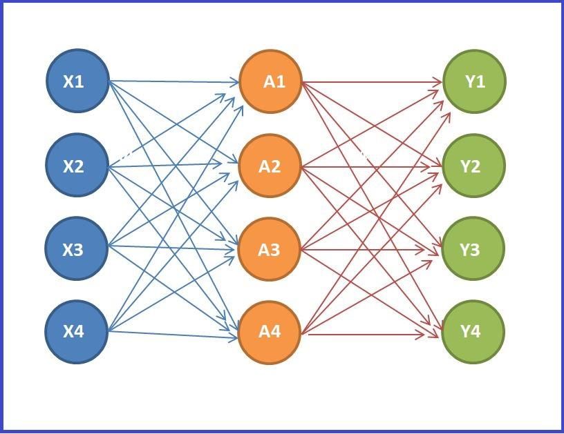
In this tutorial we will create a neural network with Python and copy its weights to a network with forward propagation on the Artemis RedBoard ATP board, and that will allow the robot car to drive alone and without hitting the walls.
For this exercise we will make the neural network have 4 outputs: two for each motor, since to the L298N driver we will connect 2 digital outputs of the board for each car motor. In addition the outputs will be between 0 and 1 (depolarize or polarize the motor). IMAGE 1
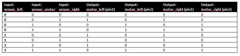
We will have four inputs, three correspond to the 3 sensors and the fourth is for the BIAS, the values will be 0 and 1, and they are assigned with the following logic: The sensors on the left and right will have a value of 1 if the distance is less than 13 cm, and will have a value of 0 if the distance is greater than 13 cm. The center sensor will have a value of 1 if the distance is less than 16.7 cm, and will have a value of 0 if the distance is greater than 16.7 cm. The BIAS will have a value of 1. Here we see the changes in this table: IMAGE 2
And the actions of the engines would be the following: IMAGE 3
Codes:
- To create our neural network, we will use this code developed with Python 3.7.3: NeuralNetwork.py
- The code we add to see the graph, as it trains after 40, 000 iterations is as follows: Graphic.py
- And now we can see the weights obtained from the connections, and which will be the ones we will use in the Arduino code: Generate_Arduino_Code.py
PID Controller
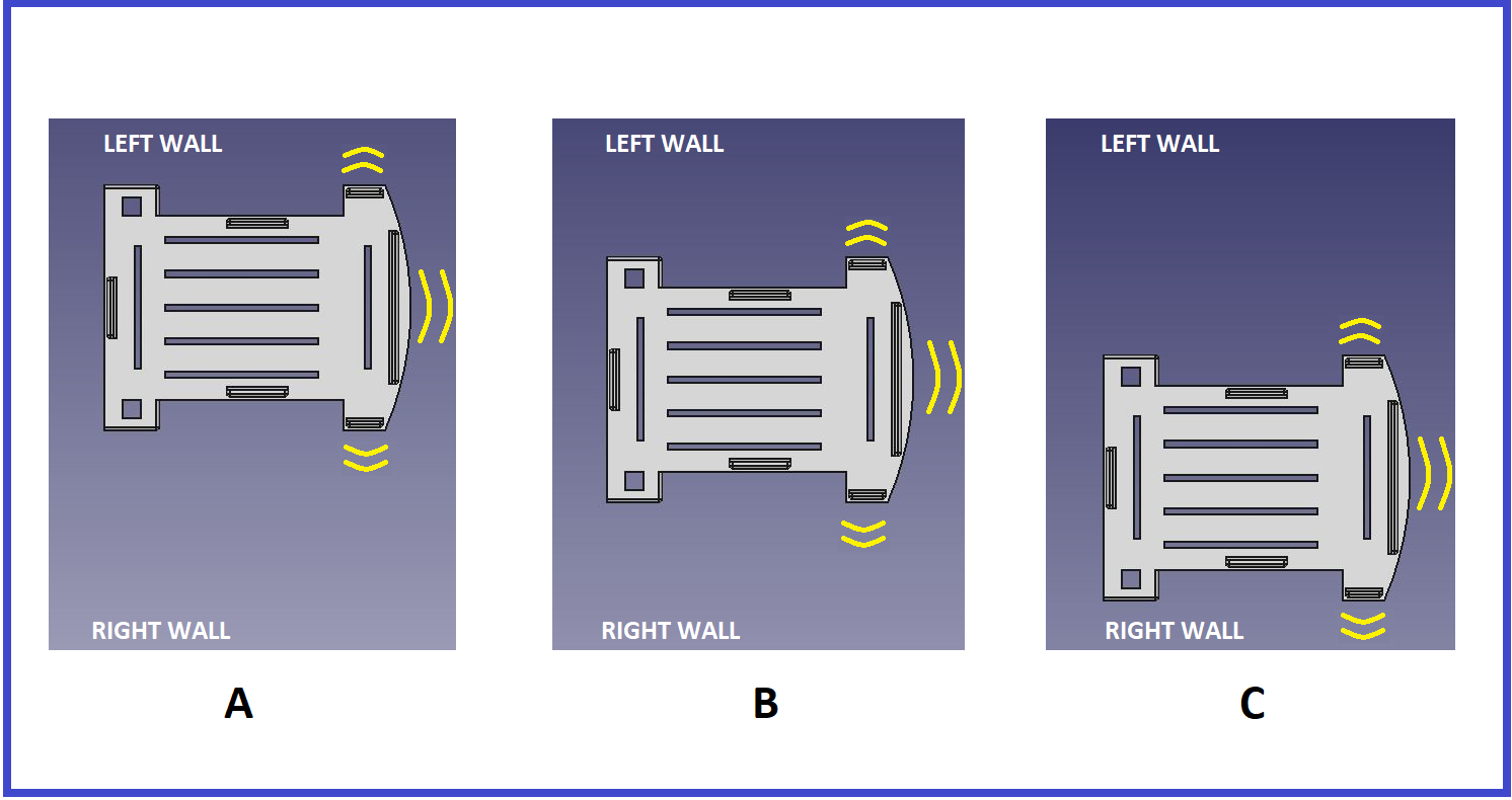
The robot is equipped with 3 analog infrared sensors, which detect the distance at which the walls are, one in front and two on the left and right sides. To calibrate the distances of the infrared sensors GP2Y0A41SK0F and GP2Y0A51SK0F, and with greater precision you can see this post: https://www.instructables.com/id/How-to-Use-the-Sharp-IR-Sensor-GP2Y0A41SK0F-Arduin/
The robot uses PID controller to maintain a central distance between the left and right walls. If the robot is near the left wall, then it can decrease the speed of the right motor and increase the speed of the left motor, to make the robot move to the right, and moving away from the left wall, and vice versa. IMAGE 1
The speeds d0 of the left engine, and d1 of the right engine are calculated with the following code:
However, the robot's movement may be unstable due to the error caused by a small time error, we have added a second correction factor to make the movement smoother. That is to say: difAnt= dif; now the speeds are applied by means of PWM signals to the two gearmotors:
Code:
The Arduino code with the configuration of the neural network and PID Controller is loaded on the Artemis board. Self_Driving_Car.ino
Downloads
Test 1
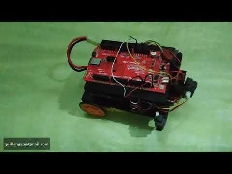
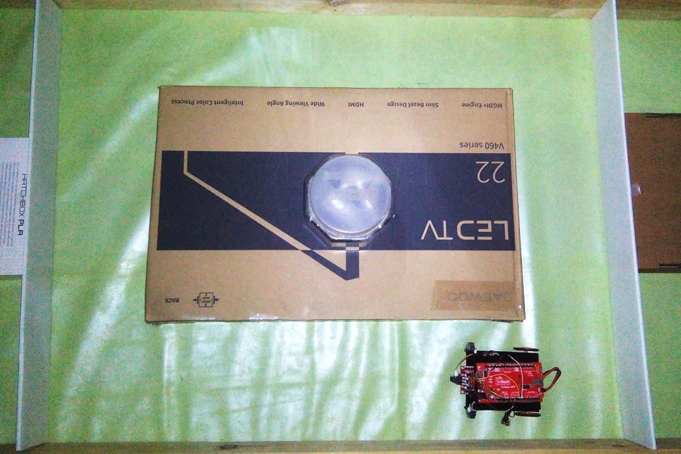
My intention is to do tests and for each change made to the robot, so first we do the test and then we add the Micro OLEd Breakout. Below, I show you the tests performed with this prototype.
Adding the Micro OLED Breakout
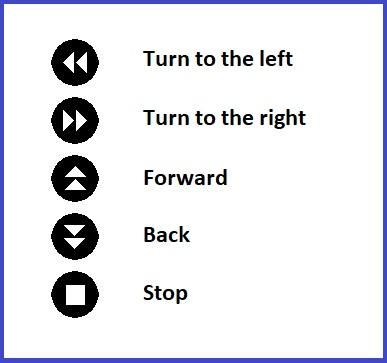
The small monochrome, blue-on-black OLED screen presents incredibly clear images for your viewing pleasure. This is why I added this device to indicate visual signals when the robot car will be in the following situations: stop, forward, back, turn to the left and turn to the right. The icons (64x48 pixels) that I have used and their function are the following: IMAGE 1
The software to get the characters of the monochrome images is LCD Assistant and you can download it at: http://en.radzio.dxp.pl/bitmap_converter/
The example code that I used from the library is: MicroOLED_Rick_and_Morty_I2C.ino
Code:
The bitmaps.h library that I obtained, you can download in the download section. Below I show you how the modified Arduino code of the previous section: Self_Driving_Car_microOLED.ino
Test 2
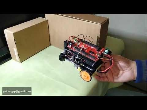
Finally, I show you some tests done with the Micro OLED Breakout: