Self Powered Ionic Wind Flier
by Poldo in Workshop > Electric Vehicles
123 Views, 0 Favorites, 0 Comments
Self Powered Ionic Wind Flier
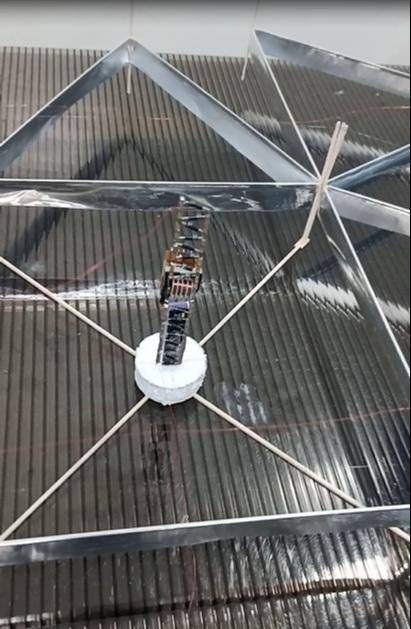

Originally inspired by Jean-Louis Naudin and then later by Ethan Krauss, I challenged myself create a self powered Ionic Wind Lifter Vehicle capable of lifting its own weight plus the weight of the self contained power plant. This was a 1-1/2 year journey that had many promising moments coming so close to my goal but always falling just short. Then, at long last, I witnessed my dream become a reality. Although I can't steer it yet or control the altitude, I did achieve lift-off! I am doing this instructable to share what I have learned and maybe inspire others to take it to the next level.
The flight time was only around 10 seconds or so before the transformer would saturate. The the battery will be exausted in 45 sec or so. Since the battery voltage will go down to 3.2V or less, permenent damage usually resuts and the ability for the baterry to fully recover after recharging is compromised.
NOTE: It is important to point out that this is a proof of concept project and is not intended as a beginner or someone who is a novice. Please do not attempt to build this unless you are comfortable working with HIGH VOLTAGE. In addition, there many nuances when it comes to the construction and implementation that are not covered or adressed here. If you build this your outcome may be different. If your like me, then use this as a working example of what is possible and apply your own inginuty and intuition when persuing this kind of project.
Supplies
DeltaX Flier:
36pcs - 1.5mm x 1.5mm x 500mm contest grade balsa wood stick
1 Roll - Light weight Kitchen Aluminum foil (10-12 microns thick)
10 Meters - Single Strand 304 Stainless Steel Wire .02mm Diameter (soft)
1/2" thick Styrofoam board
White thick poster paper
#43 AWG Magnet wire
1mm thick flat balsa wood flat sheet
Super glue
Glue Stick
Electronics:
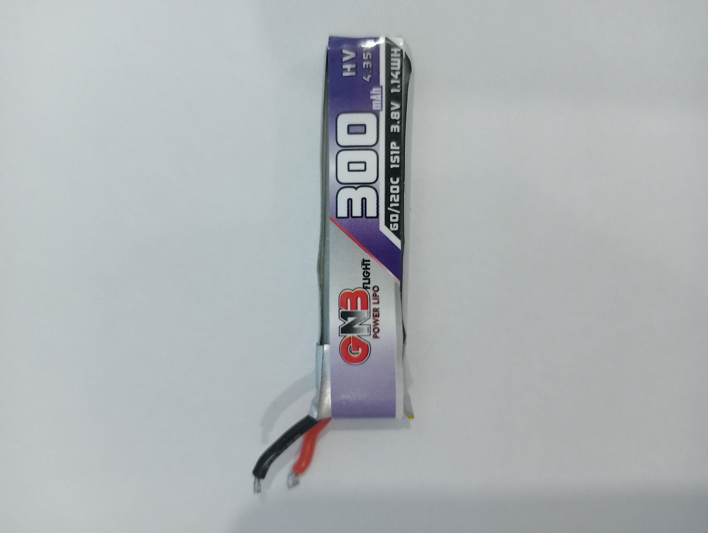
1 - LiPO Battery (Gaoneng GNB 300mAh 6.5grams)
1 - MCP73831 - Battery Charger Power Management Evaluation Board
16 - 2CL69A, 5.0mA 4.0kV 100nS, High Voltage Silicon Rectifier Diode
32 - Capacitor Ceramic 2200PF 2KV X7R 1206 (C1206X222K202T)
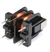
1 - UU9.8 10mH Common Mode Choke Inductor
#28AWG Magnet wire
4 - SiSH106DN, N-Channel 20 V (D-S) Fast Switching MOSFET
1 - ATTINY85-20SU, IC MCU 8BIT 8KB FLASH 8SOIC
1 - TSOP36238TT, SENSOR REMOTE REC 38.0KHZ
1 - 47uF X5R Ceramic Capacitor 16V 1210 (GRM32ER61C476KE15L)
2 - 0.1uF X7R Ceramic Capacitor 50V 0603
1 - 4.7uF Tantalum Capacitor 10% 10V 0603 (TACL475K010RTA)
3 - 10kΩ Resistor 1% 0603
2 - 10Ω Resistor 1% 0603
Support Items:
Samsung universal remote
2.5mm Diameter Heat shrink Tubing
1 - 220V AC Relay (harvest the wire for the secondary of the transformer)
Coil Winder
Weighing scale (+/- 0.01 gram resolution is best)
3D Printer
PLA Filament
Other Helpul Support Items
85C1-50Kv Meter with 500MΩ resistor - or equivilent (for measuring High Voltage)
10 Amp 350Watt Lab Power Supply
Oscilloscope
Digtal Mutimeter
A Brief History
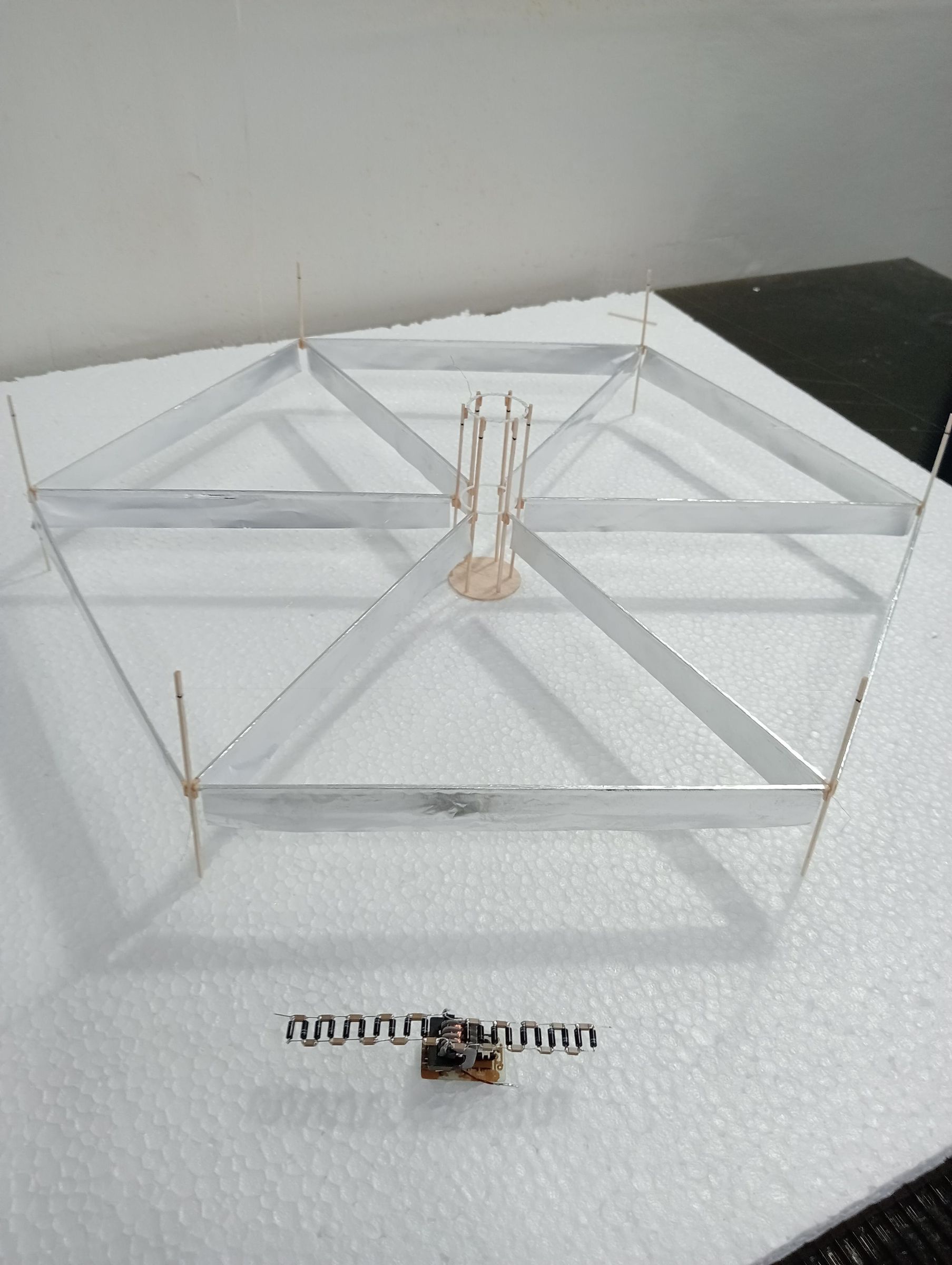
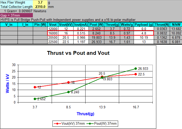
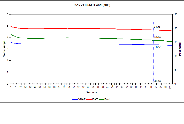
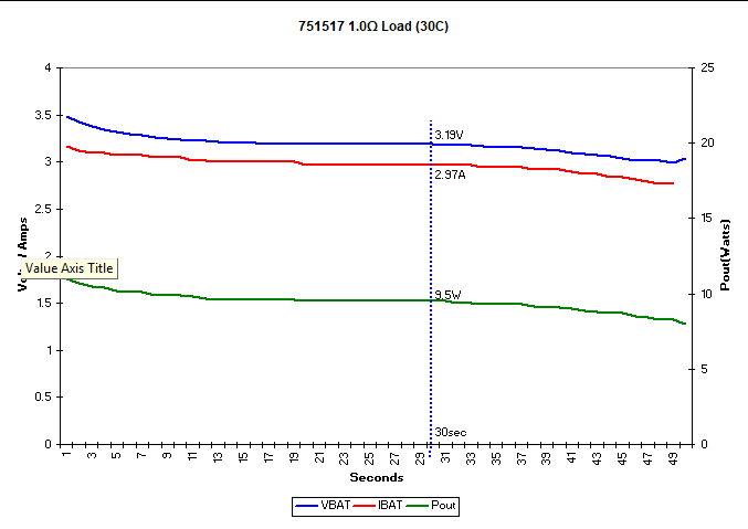
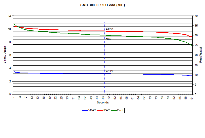
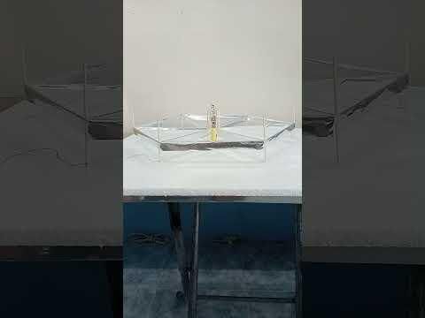
Originally, I wanted to achieve self powered flight using a single hexagon flier. After building the flier and powering it with an external power supply, I was able to take some critical data. Using this data I set out to design the smallest, lightest weight power plant that could deliver up to 25W into a load at 22kV. This took many months of experimentation not only to reduce the weight of the transformer and drive circuitry while increasing its efficiency and performance but also optimizing the the Cockcroft-Walton multiplier chain. Then my attention turned to batteries. What was the lightest most power dense battery available? I bought several different Lithium-Ion Polymer batteries designed specifically for small drones and performed load testing on them and the plots are attached. The 751517 is a 100maH 30C battery and when I stripped out the protection PCB it weighed 2.7grams. It could deliver about 9.5Watts for 30 sec. The 651723 is a 150maH 30C battery and again after stripping out the protection PCB it weighed 4.5 grams. It could deliver almost 16Watts for 90 sec. Finally I tested the GAONENG GNB-300 it is a 300maH battery rated for a Hi C discharge rate and had no protection PCB. It weighed 6.4grams and could deliver about 30Watts for 45 sec at 3.1V. So at this point I had a PCB / Transformer / C-W Multiplier / Hook-up Wires weighing approx 6.2g. My GNB300 battery weighed approx. 6.4g and my Hex Flier weighed 3.3g bringing my total to 15.9g of thrust needed for the Hex Flier to Lift-off. Looking at my data I needed about 25W or so to get that much thrust. And not only that, but my power to weight ratio would be approaching 1.6W/gram on a steepening exponential slope. The bottom line was that the max electrical efficiency that I could achieve was at best 75% and more typically like 73%. Although this is pretty good a quick calculation determined that I would need more than 34 Watts of input power while maintaining at least 3.1V. This was a real stretch for the GNB-300. Anyway, I took a chance and installed the power plant into the core of the Hex flier. The short video shows that the flier did not lift and in fact the current was too much for my Mosfets which ended up burning out after a few seconds. You can even see the magic smoke in the video.
At this point I was almost ready to give up but I knew that I was so close and that's when I noticed something in the power / thrust data. If I made 3 Hex fliers and connected them together and with my 12.6 gram payload(power plant) plus 3 times the flier weight = 9.9g the total thrust needed would be 22.5g for lift off. If I operated at close to 1 Watt /gram the power needed would be 22.5 watts not 25W but more importantly the power to weight ratio slope would be more linear around the 1W/gram. Now this seems like a small difference but at 75% efficiency I would now require only 30Watts to obtain and output power of 22.5W and that was in the range of the GNB-300 LiPO cell.
Creating three hexagon fliers and connecting them together was not going to be an easy task. First of all stringing the emitter wire on one hex flier was very difficult to say the least. It was very easy to accidentally bump one of the vertical stick and snap it in two. Also, I would need to create an artificial center joining the three structures which would add dead weight. In addition, when the power plant is installed in the center core there is a tendency for arc-over to occur since the multiplier is close to and spans across both the collector and emitter. So for several weeks I quietly thought about it and finally decided to print out a bunch of 1 inch equilateral triangles on paper and started arranging them. Ultimately, I came up with what I call the DeltaX configuration. I could see several advantages to doing it this way. First of all, I would make individual triangle fliers each one strung independently being much easier to handle. Secondly the center formed a perfect large square creating excellent isolation space for the power plant. It was also more compact that the 3 Hexagon version. The following steps detail the construction of this project.
The DeltaX Flier

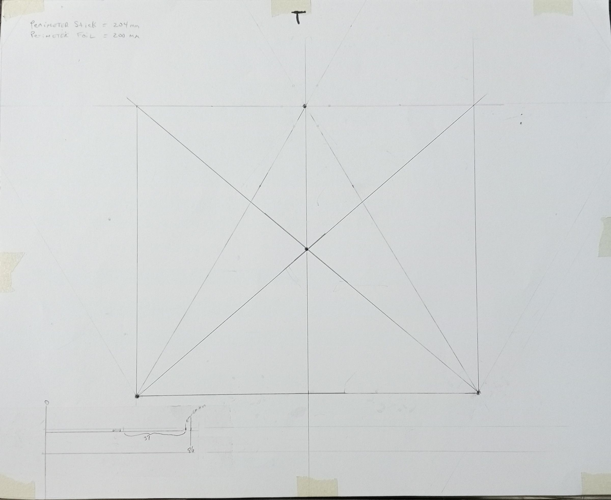

I first made a template for the triangle on some thick poster paper. Each leg of the triangle measures 206mm in length between the three vertices. The template was then laid on top of 1/2inch foam board and taped around the edges to hold it in place. I then punched small holes through the template and foam board at the vertices. This will allow the vertical sticks to be held in place while gluing the triangle structure together.
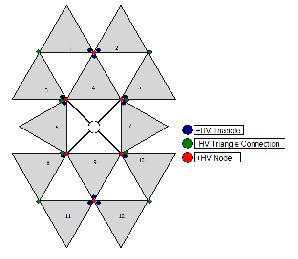
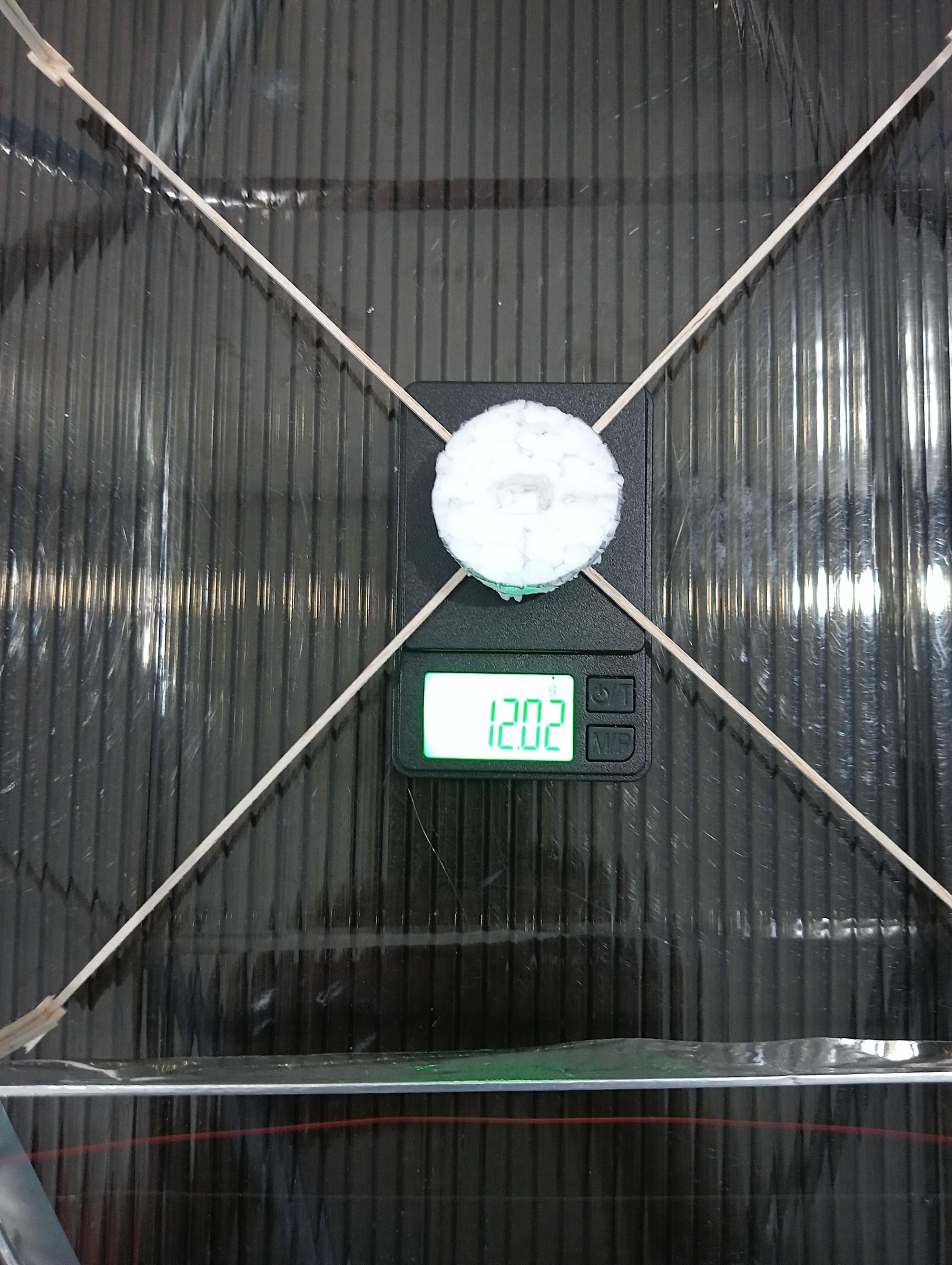
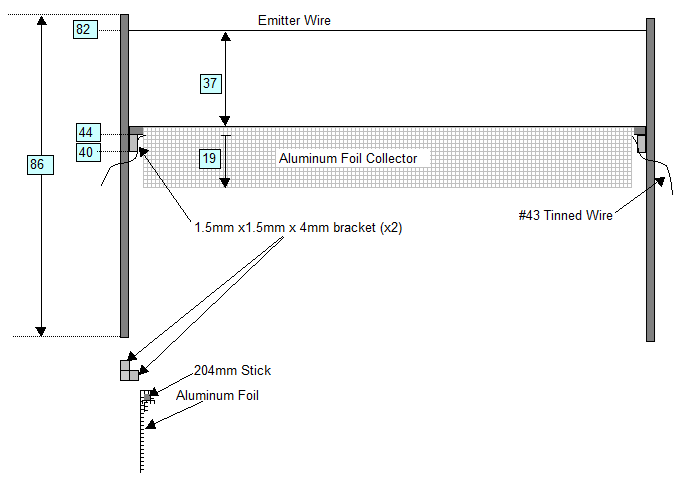
The DeltaX Flier is then made from 12 individual 206mm x 206mm x 206mm triangle shaped fliers. Each triangle flier is made of three 1.5mm x 1.5mm x 204mm horizontal sticks and three 1.5mm x 1.5mm x 86mm vertical sticks. The horizontal sticks are first wrapped with #43AWG tinned wire. This forms the electrical connection to the collectors. Next a 25mm wide x 200mm long aluminum foil strip is wrapped around the horizontal stick with the wire leaving an equal 2mm exposed stick at each end. Next the vertical sticks are cut to a length of 86mm and marked with a pencil for adding 1.5mm x1.5mm x 4mm support brackets and a small hole 37mm above where the collector stick will be attached on top of the support bracket. The hole is created by taking a very small sewing needle and attaching it to a soldering iron tip. It can then be used as a wood burning tool to make a small hole in the vertical stick at the 37mm mark. The Three collectors are then glued to the vertical sticks and the .02mm diameter stainless steel wire is strung through the small hole at the top of the stick pulled gently taught and tied off. Finally, solder all the collector wires together. The twelve triangle fliers are then glued together forming the DeltaX configuration and the electrical nodes are wired as per the drawing attached. Finally, a 1.5mm x 1.5mm x 280mm cross member is added in the center with a round 30mm diameter 1mm thick flat balsa wood disk is glued on to the center of the X-crossing to provide a platform for the power plant. The completed craft must be no heavier than 12.5grams. To achieve this you must find a supply for really light weight balsa wood stick. All balsawood is different in terms of density. Usually if it says airplane model or contest grade then you have the right one. I had to buy from several suppliers before I found the lightest one. It can be difficult finding 1.5mm x 1.5mm balsa stick. Therefore, what I did was purchase 2mm x 2mm x 500mm balsa stick. I then 3D printed a sanding jig consisting of two parts in order to sand down the stick to 1.5mm x 1.5mm. I included the stl files here. I printed them out on an Ender3 V3 KE using the Cura slicer and super quality. It wasn't very hard and didn't take that long since the wood is so soft. I used 120 Grit sandpaper. Cut the 2mm stick to a length of 204mm and place it in the 1.7x1.0 jig and proceed to sand down the stick until you hear and feel the sandpaper reach the PLA jig surface. Switch to the other 1.2x1.0 jig to finish the stick. Repeat this for all 32 horizontal sticks.
Another critical item is the aluminum foil. There are many different brands of common aluminum kitchen foil. You need to find the lightest weight product. What I did was buy several brands. I would cut a 30cm x 30cm piece of each and fold it repeatedly down to a 2 inch square or so and weighed each one. The lightest one of the bunch weighed 2.6grams and this translates to a thickness of around 11 microns or so.
My recommendation would be to prepare all the balsa sticks, aluminum foil strips and the X crossmember platform parts and weigh them before assembly. If you have obtained the right materials they should weigh well less than 12 grams.
The Power Plant
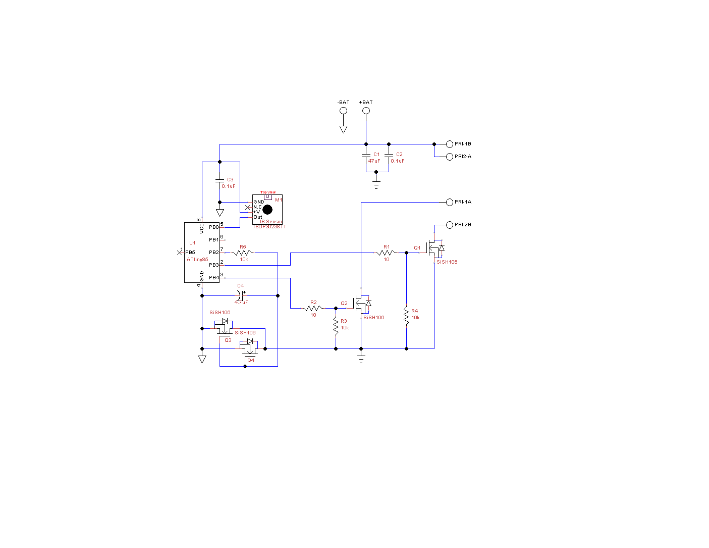
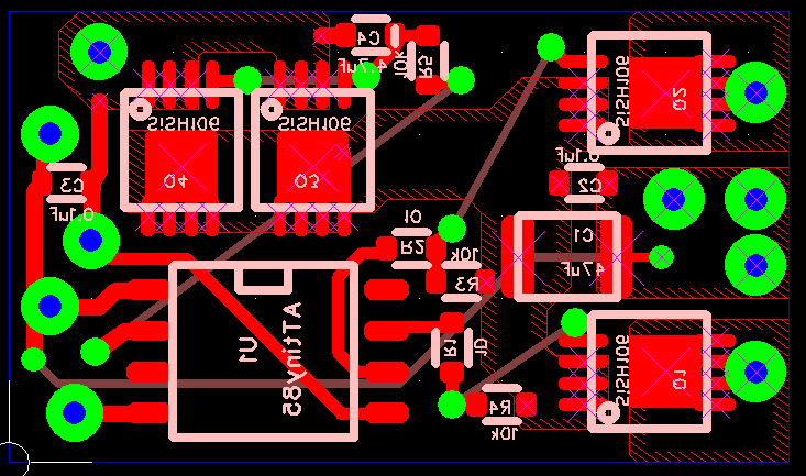
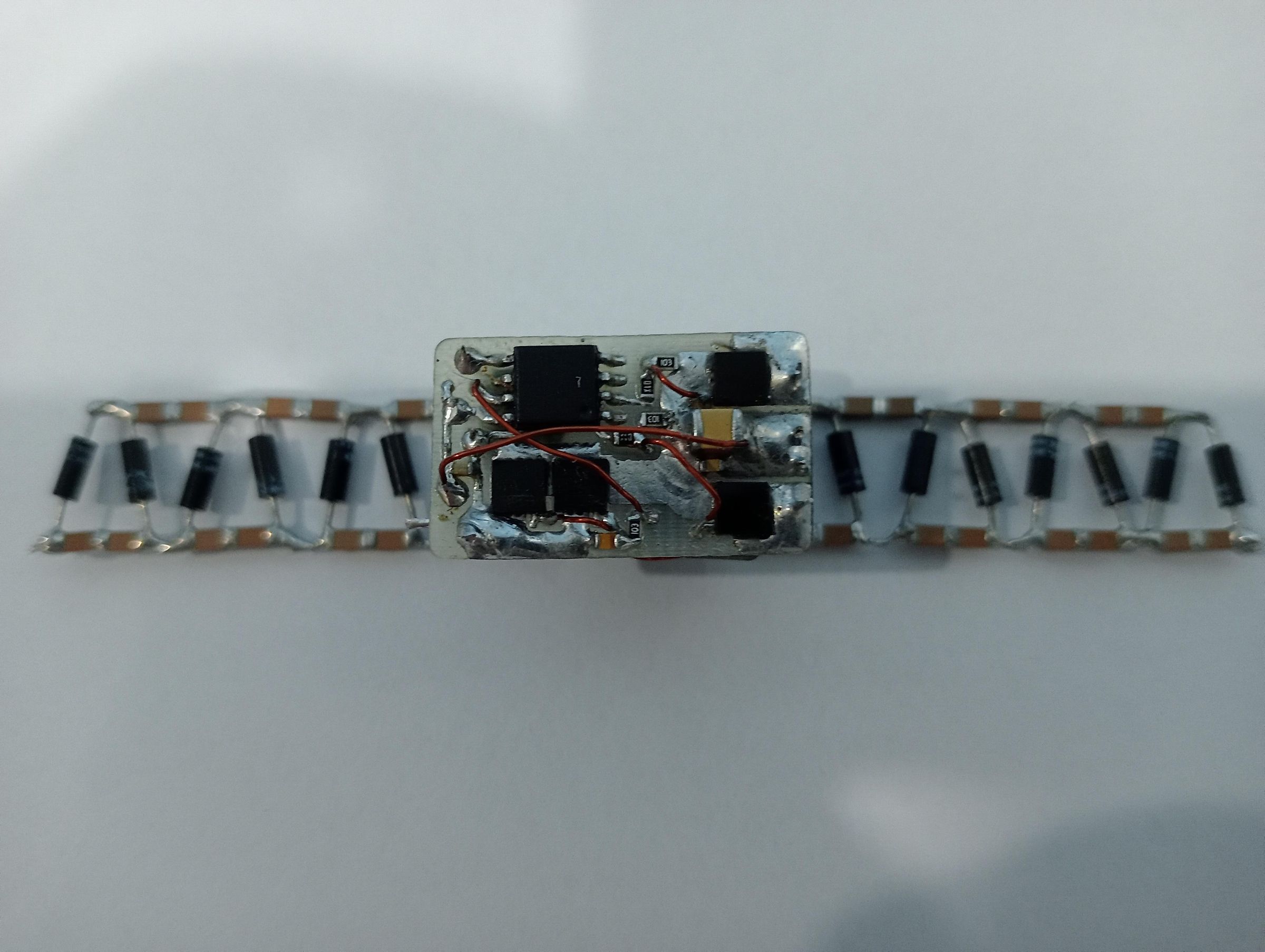
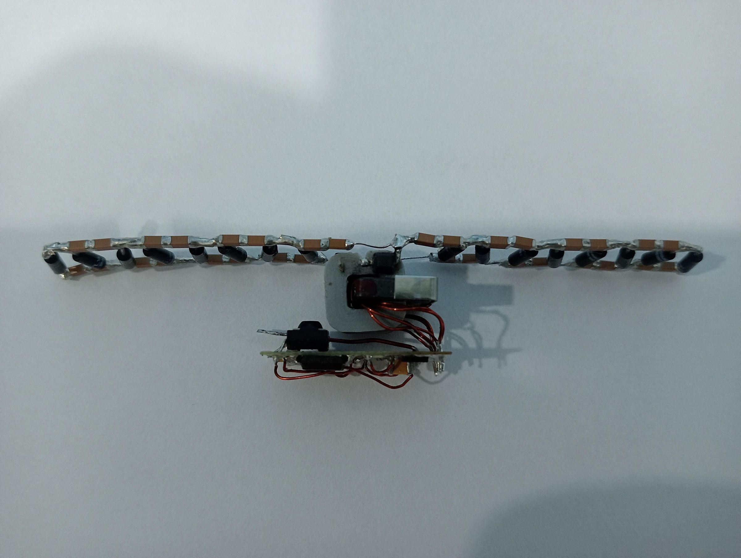
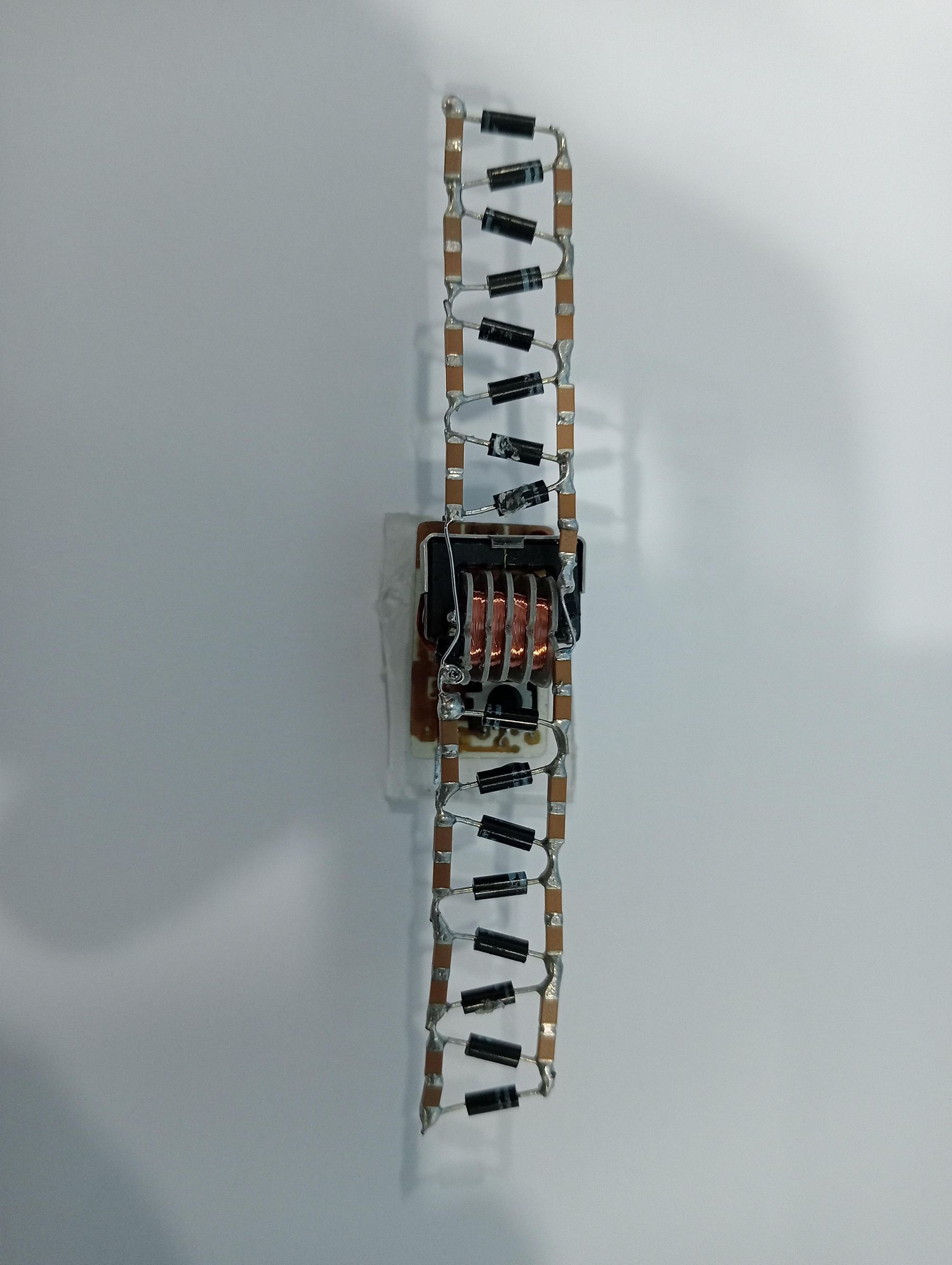
The power plant consists of four main parts; Main PCB, Output Transformer,Cockroft Walton multipler and the LiPO battery;
Main PCB
The main pcb utilizes an ATtiny85 microcontroller, IR receiver, four N-CH Mosfets and an output transformer. The microcontroller provides for receiving IR commands to turn power ON/OFF and to provide a push-pull drive signal @90kHz to the output transformer.
Q1 and Q2 are SiSH106 Mosfets and drive the primary of the output transformer. Their gates are driven by the ATtiny85 PB2 and PB3 that are a 90kHz complimentary outputs at a 50% duty-cycle with 1us dead-time. Q3/Q4 are in parallel and work with R5 and C4 to form an inrush current limiter. When the push-pull circuit is turned on there is a very large initial inrush current which pulls down the LiPO battery voltage to a point where the ATtiny will reset. The current limiter is used to slow down and limit the turn-on current such that the microcontroller will not reset.
The PCB is a single sided FR4 .024 thk x .95"L x .55"W (small size and light weight is key) The completed PCB weighs approx 1.5 grams
Output Transformer
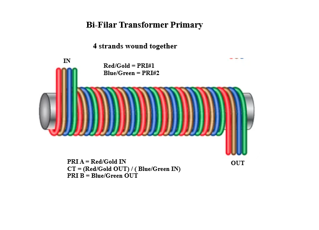
The transformer consists of a UU9.8 core with 4 Turns of (4 strands #28AWG) wound bi-filar in order to form a perfect center-tap thus each half of the primary is two strands in parallel, The secondary is 1680 Turns of (approx #46AWG) wound in four sections of 420Turns each.
The UU9.8 core can be harvested from a 10mH Common Mode Choke Inductor that can be prchased online.
The bobbin is printed in 5 seperate pieces and then glued together using super glue. It should be noted that I tried printing as one piece but its small size made it not practical. I used PLA to print the parts but ABS is better. Glue two right angle single pin male headers to each side of the bobbin to connect the secondary wires and support the completed Cockroft-Walton multiplier assembly.
Use 2.5mm diameter heat shrink tubing to cover one side of the UU core and wind the primary 4T(4 strands #28AWG) directly over the tubing. Once wound, use a little super glue in the windings to hold it firmly together.
When completed the transformer including the core weighs approx 2.9 grams
Cockroft-Walton Multiplier
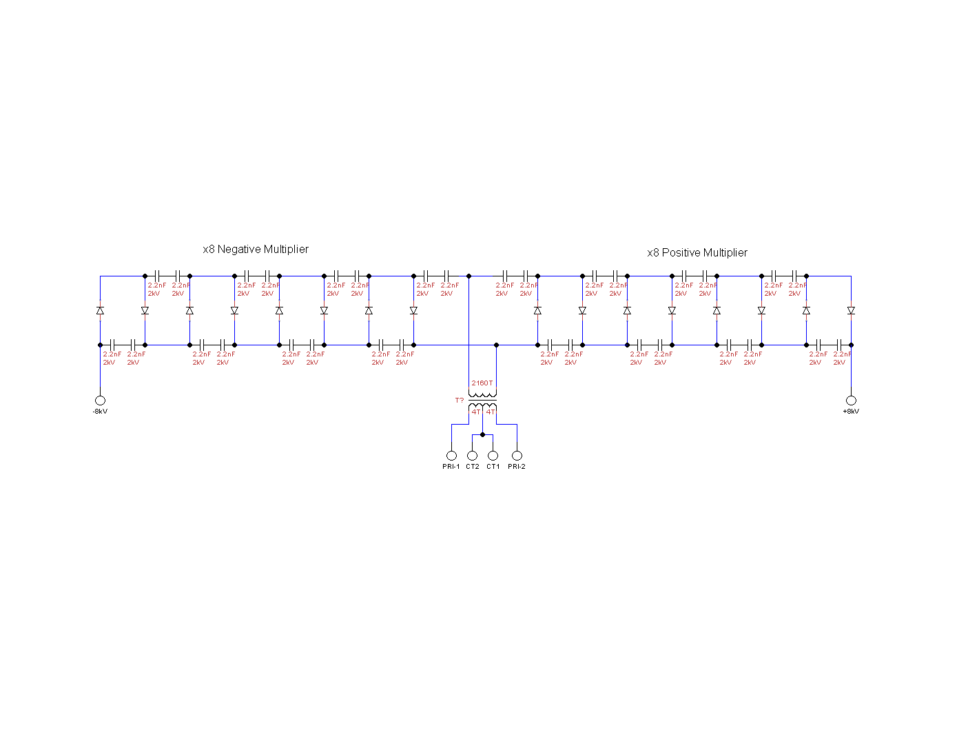
The C-W multiplier is a x16 bi-polar (-x8 and +x8) configuration. The diodes are 2CL69A and the capacitors are Holy Stone Enterprise Co., Ltd. P/N C1206X222K202T. To form the multiplier solder two each of the 2.2nF 2kV capacitors together to form 16pcs. of a 1.1nF 4kV capacitor. Cut the leads of the diodes to approx. 0.2" both sides bend and form the leads and solder directly to the capacitors at approx 30º angles as shown in the picture. This will produce a strong and light weight structure weighing approx 2.6 grams
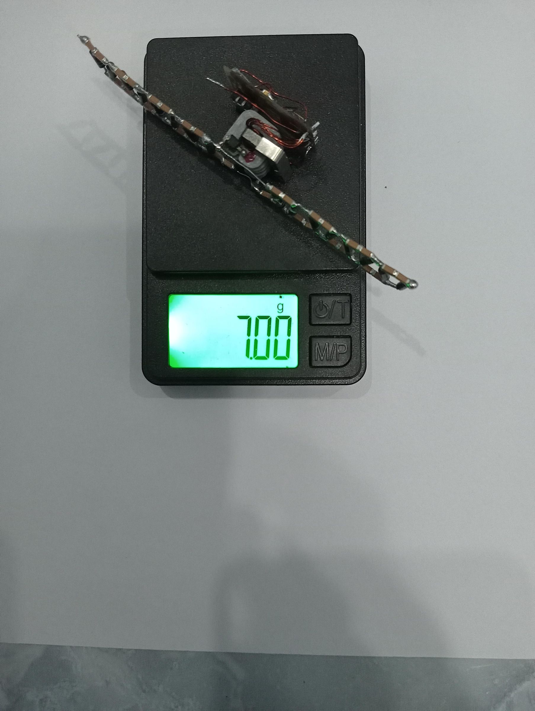
Finally, assemble the PCB, transformer and C-W multipler as shown. The total weight is approx. 7 grams.
Battery
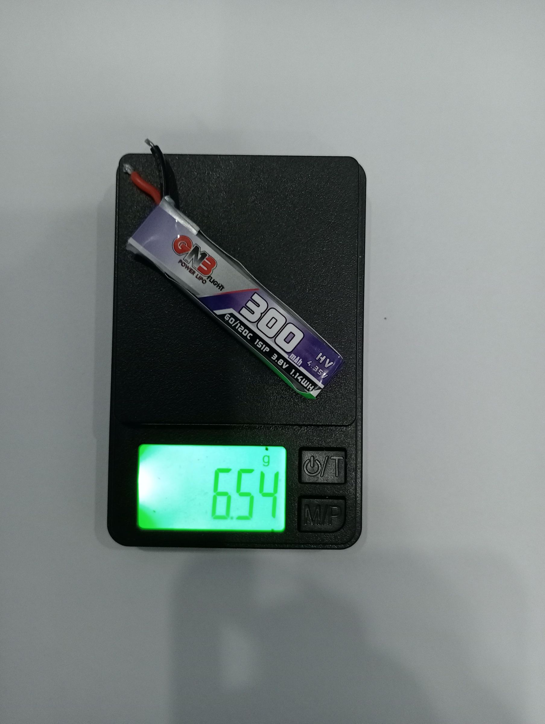
I used a 1S Gaoneng GNB 300mAh LiPO batter as the power source. The weight is approx 6.5 grams.
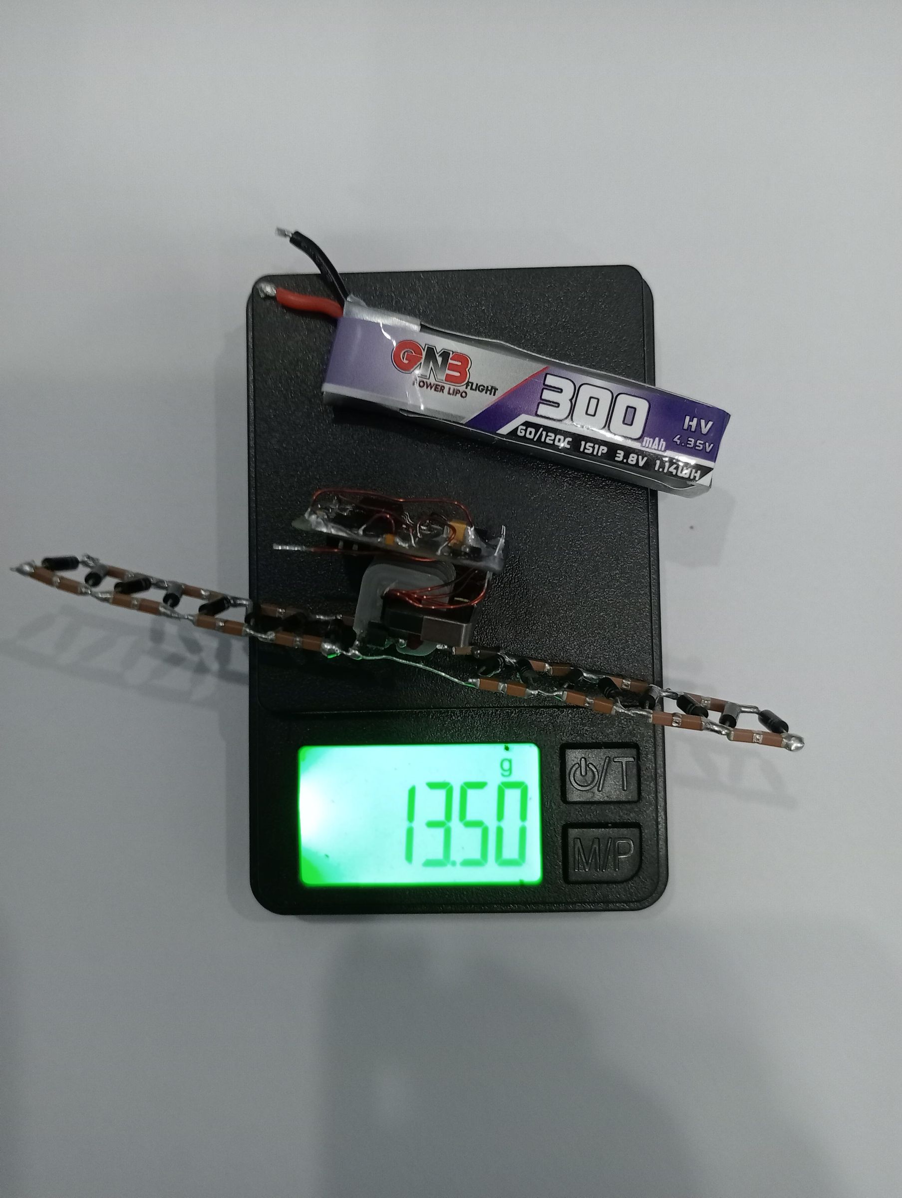
This brings the total power plant weight to approx 13.5 grams.
Code
This code was programmed using the Arduino IDE and a Arduino Nano as a programmer.
Preperaton for First Flight

Prior to installing the power plant into the Delta-X flier, I connected it off to the side and added the equivalent weight of 12.5 grams to the flier to see if it would lift. Please watch this short video explaining the IR remote and demostrating the pre flight.. Off to the left side and out of camera angle, I have the power plant connected to the flier using #43AWG wires and the flier is tethered with about 12 inches of sewing thread
Delta X1 Final Data
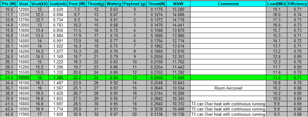
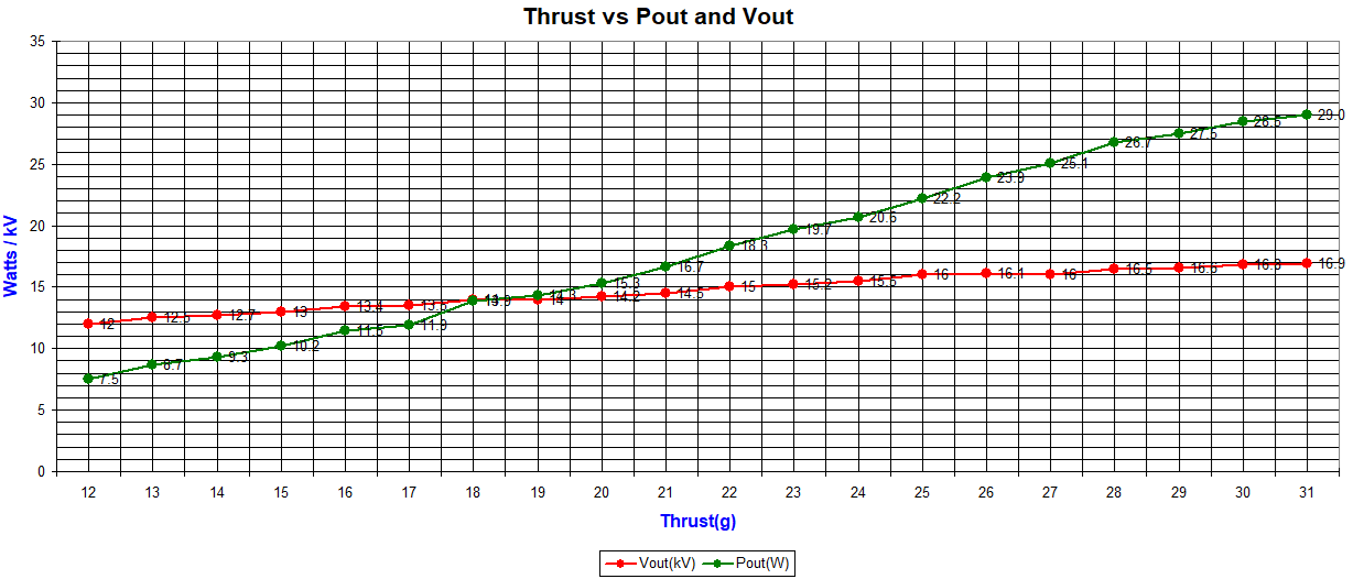
This data was taken with actual DeltaX1 flier used for self powered flight. However, I utilized a different transformer and an external powersupply off to the side inorder to have sufficient time to take careful data.
I will be attempting to enhance this project further by making it fully controllable with respect to thrust control and Pitch/Roll capability. I hope to have something to share in the comming months.