Sensors in Phone and Arduino | Serial Communication
by maker_ATOM in Circuits > Arduino
5896 Views, 78 Favorites, 0 Comments
Sensors in Phone and Arduino | Serial Communication

Sensors are one of the crucial things when it comes to building projects/robots. Many a times the sensor might be not available locally or it might take too long to ship.
Smart phone have most of the basic sensors like proximity, accelerometer, light, magnetometer, gyroscope, etc. embedded and we can in fact use these sensors in our Arduino projects.
These can be easily used for quick prototyping.
So In this Instructables I will show you how these sensors can but utilized and can be made to talk to Arduino through wired connection.
Why wired? Because we just need a USB cable to establish a communication unlike in wireless other modules are required.
Supplies
Arduino Uno
USB cable (type B) - for Uno
OTG cable (according to your phone)
A OLED display module (to show incoming data)
MIT app inventor
The Idea
We will be using MIT app inventor to build a app which will do the work of transferring collected data from sensor to phone. MIT app inventor is perfect for ones who don’t want to go deep but want the work done.
Blink | Serial Communication


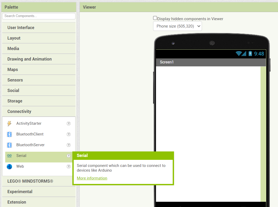


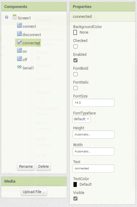


Serial communication between Arduino and android is as same serial communication between a computer and Arduino. The sender sends data bit by bit and receiver receives bit by bit.
Serial communication - Application
- Login MIT app inventor and start an new project.
- To establish a serial connection we need to include serial from connectivity tab, drag and drop the item.
- Make sure the buad rate is same as buad rate used to initialize serial in Arduino.
- Import two buttons and to connect and disconnect to Arduino and one checkbox for visual representation that device is connected. (you can rename the components and change the texts)
- Add another two button to on and off the led.
- Lets get to block coding in the blocks panel we find various events associated with various components
- Place click events of each buttons
- When connect button is pressed it will initialize the serial connect and opens a serial connection and if it opens successfully then it will check the checkbox.
- And when disconnect button is pressed it close serial communication and uncheck the check box
- Now as soon as on button is pressed it will send a byte of data which represents 1 that is led should turn on only if serial communication is open.
- Same will happen when off is pressed but instead of 1, 0 will be send indicating led should turn off.
- That’s all of designing.
- Now save the project.
- Export the apk file of our app either by qr code or download it from build tab.
- Download the app on your phone and install the app using apk.
- Phone might say the source of the app can harm your phone but install it anyway its safe.
- Do refer above pictures.
Arduino code
- First we declare a variable to store led state then in setup initialize the serial communication and define pin 13 as output as we will use build-in LED.
- Then in loop we check if phone has send any data or not if yes then it waits for about 400ms for things to get stable.
- Then parse the incoming data – what it does that checks if any int type data is available or not and waits for about 1000ms to check if more data is coming or not – this is done internally.
- And store in variable.
- And set the state of led according to the contents of variable.
int ledState = 0;

void setup()
{
  Serial.begin(9600);
  pinMode(13, OUTPUT);
}

void loop()
{
  if (Serial.available() > 0)
  {
    delay(400);
    ledState = Serial.parseInt();
    digitalWrite(13, ledState);
  }
}
Physical connections
- First connect Arduino to phone using OTG cable.
- Then open our app.
- And press connect, a msg will pop up say if to allow our to access USB device – say yes.
- Again press connect to actual connect to Arduino – the check box should be checked.
- And press on button and build-in led of UNO should turn on and after pressing off it should turn off.
Proximity Sensor


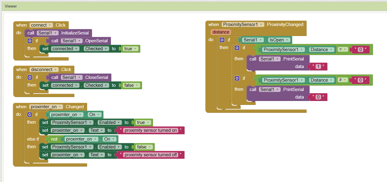
This sensor is located near front camera and used to detect whether if any object is in vicinity of the sensor or not. Application of this sensor is that when a person brings the phone close to ears to talk it detects and turns off the screen so that screen does not takes any unnecessary input if touched by any body part.
Generally, the output of this sensor is high or low depending on if the object is in the vicinity.
So we could blink the led using proximity sensor.
Application
- Include button and checkbox to establish serial communication.
- Also include proximity sensor form sensors tab.
- Do uncheck the enable checkbox of proximity sensor this way the sensor is not generating output when the app is run first time.
- Proximity sensor has an event which outputs high or low depending on if the object is in vicinity or not.
- Whenever the value changed of the proximity sensor, we send a 0 or 1 to indicate the change.
- Also, a slide switch is included to enable the sensor, or it will constantly send the data when we don’t want.
- The slide switch has a event which returns true if the switch is on or not.
Arduino code
- The code used here is same as blink as we receive 1 and 0 and turn on and off the led.
Connection
- The connections are also same as blink.
Light Sensor


This sensor detects the amount of light falling on screen. This is used in changing the brightness of screen the more ambient light falls on screen the more should be the brightness of screen and less the light falls on screen less should be the brightness this helps user to see without any issues in any conditions.
The output of the sensor is in lux which is unit of brightness of light.
The event of our use is the one which triggers when every time the light level on sensor changes so every time the intensity of light falling on sensor changes the event triggers and we will send the measured intensity of light to Arduino to display it on a oled display.
Other parameter to consider is that how often the sensor updates its value for some it may as long as 1000ms and for some it may as small as 1msec. We check this by a particular function.
Also some android devices give the flexibility to lower or increase this sample rate this can also be done.
Application
- Include connect, disconnect buttons and a check box for serial communication.
- Include a slide switch so that the sensor sends the data only when we need.
- Also include a label so that we get to know if the values sensed by sensor and the ones picked by Arduino are same.
- We are done with designing.
- Next include the same blocks for serial connections we included previously, corresponding to connect and disconnect buttons.
- Next include a block of event .LightChanged which occurs when the value generated by sensor changes.
- In this block we check first whether the serial port is open or not and if yes so it will send the value of lux measured at the moment.
- Include the event corresponding to slide switch Slide.Changed witch returns true when slide is in on position.
- And download the app.
Do refer above pictures.
Arduino code
- First all we need to initialize various parameters to set up the oled display.
- Now if you don’t have a oled display you can always use a different one.
- In setup function we set few oled parameters like text size, color, and cursor position.
- In loop section we check if there is any data incoming or not.
- If yes we will first parse the data into float.
- After parsing we pass on to oled to display the value.
void loop() {

    if (Serial.available() > 0)  {
    delay(400);
    data = Serial.parseFloat();
    display.clearDisplay();
    display.setCursor(0, 0);
    display.print("Intensity = ");
    display.print(data);
    display.print(" Lx");
    display.display();
  }
}
The Hardware
- Connect oled display to Arduino using jumpers and breadboard.
- Pins of oled display => Arduino pins (these connections for Arduino uno.
VCC => 5V
GND => GND
SCL => A5
SDA => A4
- And now connect phone to android using otg cable.
- Fire up the app and initialize the connection by pressing the connect button then toggle the slide switch.
- Try waving hand around front camera this is where the sensor is located.
- The changing value should appear on oled display as well as below the slide switch in app.
Accelerometer


This sensor is used to find the orientation of the phone. Widely used in gaming and other interactive applications.
It measures the acceleration along 3 axis x, y and z. Units considered are SI units that is ms^-2. Range of the values is -9.8 to +9.8.
xAccel: 0 when the phone is at rest on a flat surface, positive when the phone is tilted to the right (i.e., its left side is raised), and negative when the phone is tilted to the left (i.e., its right size is raised).
yAccel: 0 when the phone is at rest on a flat surface, positive when its bottom is raised, and negative when its top is raised.
zAccel: Equal to -9.8 (earth's gravity in meters per second per second when the device is at rest parallel to the ground with the display facing up, 0 when perpendicular to the ground, and +9.8 when facing down. The value can also be affected by accelerating it with or against gravity.
The events which we are interested is acceleration.Changed which triggers when ever the sensor measures different values from previous measures.
To pass the values to Arduino we wont use this but will use a timer event which is a element which triggers after every specified time is passed.
The sampling rate of accelerometer is pretty high so if we send the data when different values are measured than previous what will happen is the application will try to send new data irrespective of previous data is received or not by Arduino, hence we the timer to send the data.
So we will include a timer which ticks every specified time in msec and when it ticks we will send the data through the serial.
Application
- Include connect, disconnect buttons and checkbox to initialize serial communication.
- Also include a slider switch to enable and disable accelerometer as well as timer.
- Then place 6 labels with 2 adjacent to each other using horizontal arrangement available in layout tabs.
- Also include a slider using which we will set timers ticking period.
- Do keep the min and max value of slider 1 and 1000 respectively so that we don’t need to map them as time for timer will be from 1 to 1000msec.
- In block coding add events for connect and disconnect.
- For slide switch it is same as light sensor, a functions returns true when slide switch is in on position and enables accelerometer and timer.
- Accelerometer automatically updates itself so need of special event.
- The slider change event sets timer interval to the position of the thumb.
- And when timer ticks it send acceleration along x, y, z through serial to Arduino and updates the labels according if serial is open.
Arduino code
- We parse 3 times to read 3 axis values and print them with some formatting.
- As we have parsed these values hence they are now considered as float so we can now use them directly in other applications.
void loop(){
  if (Serial.available() > 0)
  {
    delay(400);
    data1 = Serial.parseFloat();
    data2 = Serial.parseFloat();
    data3 = Serial.parseFloat();

    display.clearDisplay();
    display.setCursor(0, 0);
    display.print("x-axis : ");
    display.print(data1);
    display.println(" m/s^2");
    display.print("y-axis : ");
    display.print(data2);
    display.println(" m/s^2");

    display.print("z-axis : ");
    display.print(data3);
    display.println(" m/s^2");

    display.display();
  }
}
The circuit
- The circuit is same as light sensor
- No changes
NOTE: The order of data is predefined that is x is 1st, y is 2nd and z is 3rd so we don’t need any special identification for that purpose.
Gyroscope


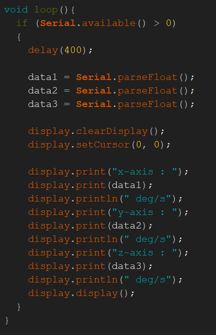

This sensor measures rotational speed along three axis x, y and z. Unit of measurement is degree per second.
Application
- Include connect, disconnect buttons and checkbox to manipulate serial communication.
- Also include a slide switch to enable and disable gyroscope as well as timer.
- Include 6 labels, 2 each in horizontal arrangement.
- Include a slider to change the ticking time of timer.
- In block coding add events for connect and disconnect.
- For slide switch a function which returns true when switch is in on position and then enables gyroscope.
- As timer ticks it sends values from gyro to Arduino and updates the labels.
- And the slider changes the ticking time based on its thumb position.
Arduino code
- The code parses three times and displays the values using OLED.
void loop(){
  if (Serial.available() > 0)
  {
    delay(400);

    data1 = Serial.parseFloat();
    data2 = Serial.parseFloat();
    data3 = Serial.parseFloat();

    display.clearDisplay();
    display.setCursor(0, 0);

    display.print("x-axis : ");
    display.print(data1);
    display.println(" deg/s");
    display.print("y-axis : ");
    display.print(data2);
    display.println(" deg/s");
    display.print("z-axis : ");
    display.print(data3);
    display.println(" deg/s");

    display.display();
  }
}
Magnetometer

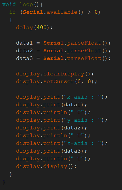


This sensor measures values of magnetic field along three axis with units in tesla.
Mostly used in digital compass to show direction. The sensor installed in phone is sensitive enough to measure geomagnetic strength but we can also play around with household magnets (fridge magnets).
Application
- Include connect and disconnect button and checkbox for serial communication.
- Include slide switch to enable and disable magnetometer and a timer as well.
- A slider to change ticking time of timer.
- In block coding add events of connect and disconnect.
- Add event of switch.Changed and in that if switch is on it enables the sensor or else disables it.
- Include event of timer which sends the measured values from sensor to Arduino and updates the labels.
Arduino code
- The code parses float data and displays with some formatting.
void loop(){
  if (Serial.available() > 0)
  {
    delay(400);

    data1 = Serial.parseFloat();
    data2 = Serial.parseFloat();
    data3 = Serial.parseFloat();

    display.clearDisplay();
    display.setCursor(0, 0);

    display.print("x-axis : ");
    display.print(data1);
    display.println(" T");
    display.print("y-axis : ");
    display.print(data2);
    display.println(" T");
    display.print("z-axis : ");
    display.print(data3);
    display.println(" T");

    display.display();
  }
}